• TalkBass has been independent since 1998. Add your voice.
    Create a free account to reply to discussions, view embedded media, and browse with fewer display ads.
    Join freeLog in
    Want zero display ads or expanded classifieds tools? Compare plans.

Driver Specification McKenzie C15B

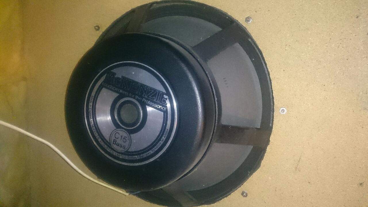
Probably no chance of this, but what the hell... I could do with making a new and smaller cabinet for my bass rig, but naturally I really need the speaker spec. The current cab was almost certainly not designed for the speaker, so there's no help there. Its a Mckenzie 15 inch driver from I think the early 80s, and although there are some specs for McKenzie drivers of various powers on line I'm not sure of the wattage of this one, and I also think its a different design to any of them judging by the looks of the magnet casing and the labelling.

Here's a photo of the thing. As can be seen it says C15 Bass, printed, not on a separate sticker or label, and the only other markings I can find are the digits 1111 on the cone itself. It has simple solder terminals, not any kind of screw connector BTW.

I'm not playing in public at the moment so shelling out for a complete new cabinet and driver seems unjustifiable, but I really need some space in the music cupboard having just bought one to many instruments...

DSC_0014.JPG
 
Thanks, I had found that, but judging by the photo its a different driver.

Thinking about it, although I lack the facilities to do a proper set of measurements, I probably could contrive to measure the free air resonance, which while it wouldn't definitively tell me I was looking at the right figures it could at least tell me if I'm looking at wrong ones...
 
I believe the C series had several variants, so perhaps there is missing information from your model number.

I checked to see if I had any docs., but all I had was McCauley.
 
from the specs shown on the link the bass drivers use a 4" coil as opposed to 3"

could be same cast basket, magnet could be same too yours might have a different cover.

the 2 bass designed drivers have resonance of either 45 or 29 hz
magnet weight slightly different by few ounces. probably same gap same basket different magnet coil/cone for application. both vented gaps, thermal power similar 400 or 500 watts. coil/xmax depth similar around 4mm, real world power handling at 10% distortion same typical 90 to 180 watts. depends on volume of box.

4" coil 45hz driver for high powered smaller PA LF driver 2.8 to 3.4 cubic feet
4" coil 29hz driver for musical instrument applications 3.2 to 3.8 cubic feet

for the most part fs is usual 30 to 45 ish
and if your looking to build a smaller box without getting to boomy the usual 3.0/3.2 cubic feet be fine.
likewise Fs of most those drivers do fine with typical 40/45 hz tuning or Fb
15" speakers are not the krapshoot most seem to believe.

getting a true alignment of course not possible. workable volume for good power handling always on the smaller size.
to small = boomy, woulnt go smaller than 2.8 big box = flatter response less power. 3 cubic works well 3.6 to 4 on the big side for that "big box" sound

id love to say ohh thats a C15 blah blah blah a perfect QB3 is 3.134 cubic feet at 36.784 hz

until then lol 3 cubic at 40hz will work it usual magic ;) if your looking for smaller/ ish box
 
Last edited:
  • Like
Reactions: JimChjones
Like I said, we really do not know what you have, nor how it might tune/perform without additional information.

Guessing is fine as long as you are aware that it's a guess and since I'm pretty sure there were several variants, but I do not recall the differences (but I do recall that they were pretty significant).

I checked around, but all my reconing buddies have recently retired, and recall similar to what I do but none had any real data or suggestions as to where you might be able to find it. They are a long gone UK company that at one time was IIRC associated with Warfdale, but Warfdale had new ownership years back so it looks like ancient history.
 
Thanks all, that's pretty much what I feared. Bogeybass makes a good point though, bearing in mind the current box was not AFAIK scientifically designed, but has been adequate over the years, its quite possible that if I at least get the free air resonance I can approximate something. Its probably within my skills to construct a box where I can vary the port width to attempt some minor tuning too.
 
Last edited:
pretty much depending on fs 30, 40, 50 will put you withing fs of speaker or within few hz of a alignment. likewise with typical 15" 3 cubic is close enough safe zone. not to big not to small. going super huge is impractical. 2.8 or 3 or 3.8 its pretty simple. and wont be some horrible thing knocking earth off its axis. lol 3.2 / 3.4

cutting/adding/ sliding ports is pain in the butt. as mentioned wanting to experiment with 15"
fs range from 29 to 48ish so 30, 40, 50 is about all you really care to hear to actually have noticeable effect.

port pluggin easiest way to go. good " experiment box" to have fun at 3 cubic feet. is to make a 3.3 box. adding ports and driver will take up about .25 .3 volume so you end up with 3 cubic feet.

now use 6 x 2" round ports. yes six. 3 on each side of driver. cut them all to 5.5 inches in length.

6 ports = 50 hz
4 ports = 40 hz
2 ports = 30 hz

you can plug/ unplug at any time to change tune.
 
Last edited:
  • Like
Reactions: JimChjones
now use 6 x 2" round ports. yes six.
That's very smart.

I was considering a slot shaped port, probably with a divider, on the bottom of the cabinet and making the whole bottom of the box detachable and screwed onto battens as below. That way I could screw it down against 'shims' to vary the cross section of the port. Your multiple port setup looks an awful lot easier and more convenient for lab testing. I just need the lab [grin].
adjustablevent1.jpg


May I bother the assembled with a few more questions?
Thiele/Small is new to me, I've been happily using the same box for decades, so the implications of all this are new to me, and in any case the maths are out of my league. I can grasp the concept that (ignoring surface effects, friction and the like) various different combinations of port cross section and port volume can end up having the same effect on the resonance inside the enclosure. However are there any audible differences? I see commercial boxes with round ports in the middle of the enclosure, or with slot shaped ports at the bottom or side. Are there pros and cons, beyond the obvious ones of manufacturing options and surface effects against a floor? Do they *sound* different?

A second point is cabinet materials. The box that I could cheerfully pick up and sling round the place when I was 25 is a lot more cumbersome 30 years later. I was considering making a sandwich of something like 12mm mdf with 6mm ply on the outside to get something that approaches the durability of a 100% ply box, but is rather cheaper, maybe even lighter. There shouldn't be any downsides to that should there?

The other thing is cabinet internal bracing. I'm accustomed to lightweight boat building where we brace panels with ply webs, rather than a single heavier batten. Much less weight for the same stiffness (and volume), but are there implications if the main enclosure contains a whole load of partial dividers rather than being a simple chamber? At least if they are kept clear of the vents? If there was a grid of say 3 inch deep webs at 6 inch intervals on the inside (as below) then I could go an awful lot lighter on the skin for the same panel stiffness. This sort of complexity is bearable if I get the web pieces laser cut from mdf so they all fit with no fettling required, and modern gap filling glues should prevent any chance of rattles. But the result is a cabinet that's full of little semi chambers which could have all sorts of little resonances and interactions? Could that cause problems? I can see that you would need to keep the webs well clear of the ports so that air can flow in and out of those without interruption, but I don't know whether air movement in the main body is a consideration. I suppose one could juggle the spacings so that all the chambers are slightly different in size.

aneggcrate.jpg

And lastly, I am familiar with the business of measuring the voltage across a speaker to calculate impedance against frequency - I did a school physics project back in the mid 70s where I measured that against a variable size enclosure which was the last time I thought about this stuff! I took it on trust back then, but on reflection it seems too easy as a means of establishing enclosure sonic performance. Is it really reasonably trustworthy, at least on an 'only rock n roll basis?
 
For the most part port shape doesn't matter (avoiding extremely small dimensions, and clearances in the case of a slot port).

Don't bother with MDF, much heavier and by the time you laminate with plywood, will be even heavier and more costly

There are all kinds of bracing options, your web bracing can work fine but is a lot of work compared with the small amount of weight savings.
 
Thanks. Trouble is where I live mdf is way cheaper than half-decent birch ply. I suppose what I could do is build my box as light as I dare, and if I run into problems with resonance zap another skin onto the outside. Thanks for all the valuable input everyone.
 
I'd blind test two identical boxes (one standard ply, one birch ply) any day of the week against any auditory "expert". I'd bet dollars to doughnuts the results would be few if any could distinguish the difference.
 
  • Like
Reactions: JimChjones
Thanks. Trouble is where I live mdf is way cheaper than half-decent birch ply. I suppose what I could do is build my box as light as I dare, and if I run into problems with resonance zap another skin onto the outside. Thanks for all the valuable input everyone.
Who said use birch ply?

There are all kinds of inexpensive plywood that is a far better option than birch for the average use. This isn't rocket science, the industry solved all these problems decades ago (except for the lowest end builders).

If you feel that you have a better way, best of luck. The wheel doesn't NEED to be reinvented again, but there are always those who suppose that there is a better shape for the wheel than round.
 
If you feel that you have a better way, best of luck. The wheel doesn't NEED to be reinvented again, but there are always those who suppose that there is a better shape for the wheel than round.
All true, but it may be that its cost effective for me to build my one round wheel with construction detail that no sane production engineer would consider. And I'll admit to flying the odd kite. When you folk who know ten or a hundred times more than I do shoot 'em down I learn, and I'm very very grateful for the lessons. Thanks again to all for the assistance, which has been more than I dared hope for.
 
  • Like
Reactions: agedhorse
I can grasp the concept that (ignoring surface effects, friction and the like) various different combinations of port cross section and port volume can end up having the same effect on the resonance inside the enclosure. However are there any audible differences? I see commercial boxes with round ports in the middle of the enclosure, or with slot shaped ports at the bottom or side. Are there pros and cons, beyond the obvious ones of manufacturing options and surface effects against a floor? Do they *sound* different?

a poor design will have a different sound, on average not a noticeable sound. the real main concern is audible distortion with a port opening that is too small. the velocity of pressure leaving the port can cause distortion often referred to as chuffing. likewise depending on the selected tune frequency for specific driver can be very audible. likewise with larger cones like 18" speakers, its better practice to try and have equal pressure leave the box by having a flared round port in each corner of the box. large cones at high spl experience distortion called cone rocking when the cone warps or distorts unevenly. again have equal pressure leaving the box and not just a single source will help reduce cone rocking. a slot port or only 2 ports to the side or bottom etc etc can increase the effect of the distortion. likewise ports located at the bottom of the cabinet share another wall or floor, and can change tune as well. i have used the same equal pressure concept with smaller cones like 15, 12 and 10" drivers, cone rocking isnt as evident but does happen and can be reduced in the same manner.

a experienced builder or high fi speaker builder will often stand ground that a flared round port or dual flared round port is the most accurate and better sounding port, likewise slot ports share walls of the cabinet and need alot of correction factor. even with software you can expect 20 to 30% error in slot port calculations. tuned round ports which share no walls are very accurate. combined with a flared opening inside the box and exit. you will often find flared ports that exceed ideal velocitys tend to still not show signs of chuffing. a well designed flared multi round port with equal pressure is considered incredible more accurate sound wise and likewise easy to calculate.
 
Thanks again.
I have to know something about aerodynamics for other stuff, and last night I was looking at my first drawing of a possible box with a slot port and trying to visualise air moving in and out, and wondering about end effects. It seemed to me that if the body of moving air was going to have to turn a corner as it entered a slot port there were going to be all sorts of odd effects, and the actual size and movement of the mass of air moving was going to be somewhat unpredictable and require significant R&D to get right. The slot ports look nice to my eyes, but I was coming to the reluctant conclusion that, with the amount of tuning I am actually prepared to do and the facilities I have, it was going to be rather difficult to get a reasonable approximation first time.

What about mechanical properties of round ports? I was agonising to myself about how to make nice and accurate sized flare ended ports when I realised that these are the days of 3D printers and I have a friend who owns one... Producing the things to a designed size should actually be quite easy if ABS of moderate thickness will do the job. Presumably the outer end should have a 90 degree flare and be on the same plane as the speaker. What about the inner end? Presumably that's free inside the cabinet body? Should the bell actually turn something like 180 degrees so the air goes past no sharp edges? Is something like 1mm thick ABS tube going to cut the mustard, or does it need to be more rigid? If I buy 50mm waterpipe or something and fabricate the bell ends will that do the job?