
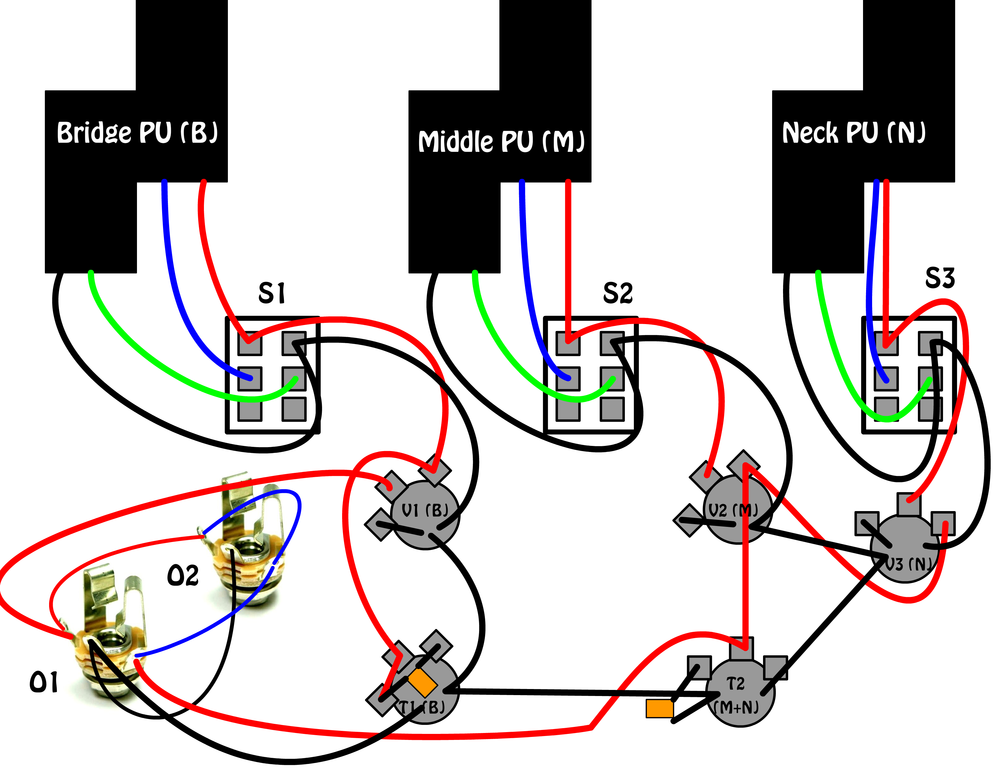
So this is the first schematic I have ever drawn up. It is for a bass I am building this summer and is pretty complex:
So there will be 3 P pickups (bridge, middle, and neck), with each having it's own series/parallel 2 way switch. The bridge pickup will go to a tone pot wired so that the bass instead of treble is cut (in series?). I am doing this so that I can solo the bridge to sound like a guitar for a bass + drum project. The middle and neck pickups will each have a separate volume pot and 1 standard tone pot for the 2 (wired like a jazzzzz bass). There will also be a Rickenbacker style stereo output that allows all 3 pickups through the output on the bridge side when no cable is inserted into the output on the neck side. When a cable is inserted to both of the outputs, the bridge side is the bridge pickup only and the neck side is the neck and middle pickup. Please do not go easy on me. This being my first schematic I expect it to have many mistakes or inefficiencies:
S1 = bridge PU series/parallel switch
S2 = middle PU series/parallel switch
S3 = neck PU series/parallel switch
V1 = bridge volume
v2 = middle volume
V3 = neck volume
T1 = bridge tone (wired in series i think? it's supposed to cut bass)
T2 = middle + neck tone (standard wiring)
O1 = output 1 (bridge only or all 3 PUs)
O2 = output 2 (neck + middle)
So there will be 3 P pickups (bridge, middle, and neck), with each having it's own series/parallel 2 way switch. The bridge pickup will go to a tone pot wired so that the bass instead of treble is cut (in series?). I am doing this so that I can solo the bridge to sound like a guitar for a bass + drum project. The middle and neck pickups will each have a separate volume pot and 1 standard tone pot for the 2 (wired like a jazzzzz bass). There will also be a Rickenbacker style stereo output that allows all 3 pickups through the output on the bridge side when no cable is inserted into the output on the neck side. When a cable is inserted to both of the outputs, the bridge side is the bridge pickup only and the neck side is the neck and middle pickup. Please do not go easy on me. This being my first schematic I expect it to have many mistakes or inefficiencies:
S1 = bridge PU series/parallel switch
S2 = middle PU series/parallel switch
S3 = neck PU series/parallel switch
V1 = bridge volume
v2 = middle volume
V3 = neck volume
T1 = bridge tone (wired in series i think? it's supposed to cut bass)
T2 = middle + neck tone (standard wiring)
O1 = output 1 (bridge only or all 3 PUs)
O2 = output 2 (neck + middle)