Sell the speaker. Put the money toward a used, well designed, lightweight cabinet. Use the extra time to practice your instrument.

Enjoy the benefits of a premium membership!
Upgrade Account
-
TalkBass has been independent since 1998. Add your voice.
Create a free account to reply to discussions, view embedded media, and browse with fewer display ads.
Join free Log in
Want zero display ads or expanded classifieds tools? Compare plans.
You are using an out of date browser. It may not display this or other websites correctly.
You should upgrade or use an alternative browser.
You should upgrade or use an alternative browser.
Light weight cabinet build
- Thread starter 41hzthunder
- Start date
More options
Who Replied?

Yesterday was spent mostly helping my daughter with a bathroom addition. I do not like doing tilework, even if I'm fairly good at it.
I ran some cone excursion models in WinISD. These suggest the E-140 hits the published Xmax around 125 watts. I recall from a thread that Bill Fitzmaurice said the E-140 become "Xmax challenged" at this wattage. I really am having a hard time believing this. It doesn't affect my project, as the amps I'm using won't push the driver. So, as a practical matter, I should move on.
The 4.2 cubic box seems to offer little advantage over the smaller boxes and I'm gravitating toward something 3.2 to 3.75 cubic foot range. As such, no models for 4.2 cubic foot were created. Pretty clear that the higher the tuning goes, the lower the excursion will be. Here's the Cone Excursion models:
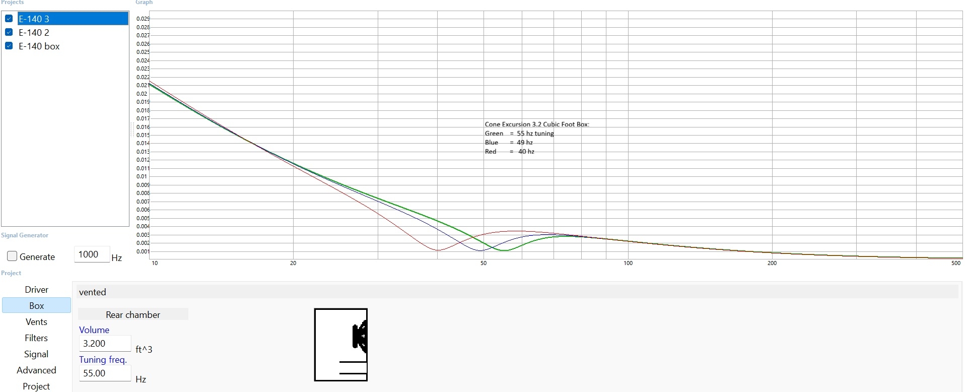
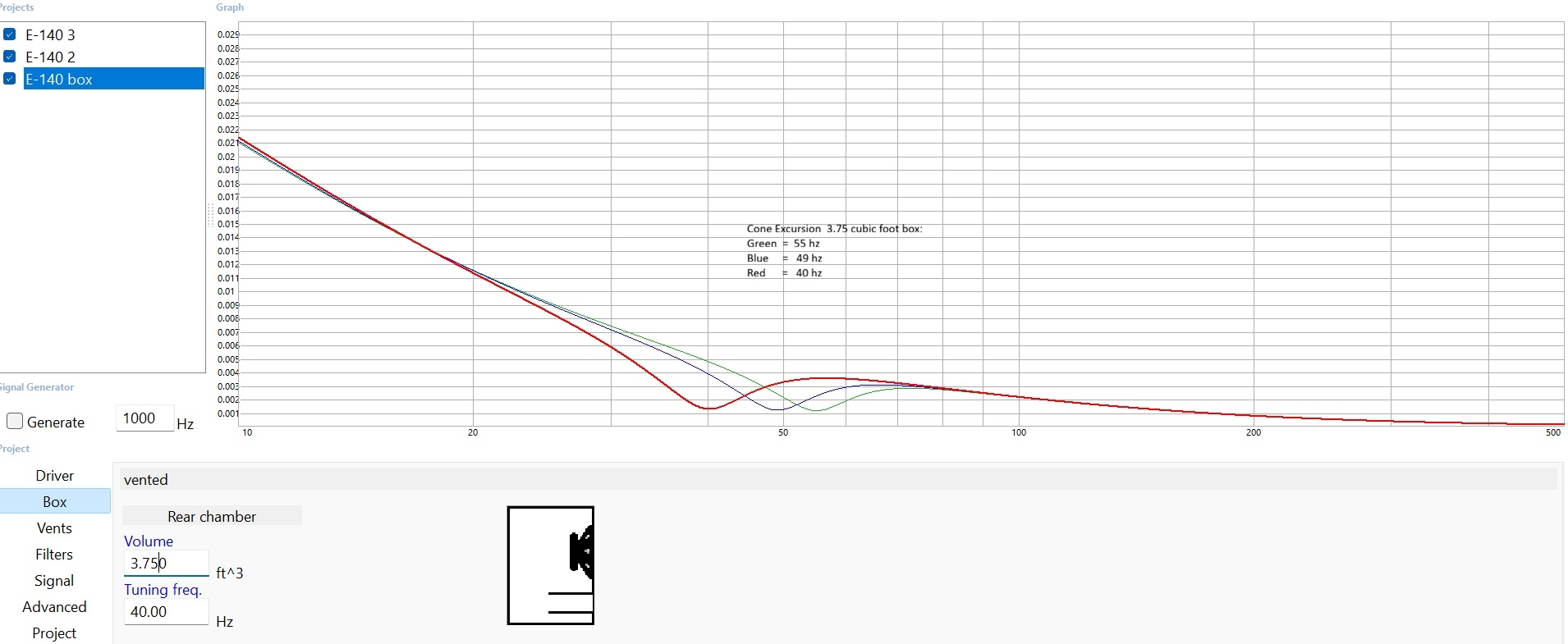
I ran some cone excursion models in WinISD. These suggest the E-140 hits the published Xmax around 125 watts. I recall from a thread that Bill Fitzmaurice said the E-140 become "Xmax challenged" at this wattage. I really am having a hard time believing this. It doesn't affect my project, as the amps I'm using won't push the driver. So, as a practical matter, I should move on.
The 4.2 cubic box seems to offer little advantage over the smaller boxes and I'm gravitating toward something 3.2 to 3.75 cubic foot range. As such, no models for 4.2 cubic foot were created. Pretty clear that the higher the tuning goes, the lower the excursion will be. Here's the Cone Excursion models:
Its an option. Still, defining what a well designed cabinet actually is seems critical to that course of action.Sell the speaker. Put the money toward a used, well designed, lightweight cabinet. Use the extra time to practice your instrument.
There are many. You don't have to go to the extreme top end, but stay away from the cheap stuff.Its an option. Still, defining what a well designed cabinet actually is seems critical to that course of action.
When I started this project I chose box sizes based on two points: 1. historically I have been told bigger boxes = bigger bass, and 2) the TL606 is about 3.2 cubic feet. The bass player in my friend's band uses a TL606 with the EV in it. His bass seemed to lack deep low end, but was run through sound reinforcement and I probably wasn't hearing the TL606. A lot of bass players like this box. With the JBL and tuned to 40 hz the box would likely have low SPL in the first and second harmonic (5 db down at worst), however at higher tuning the second harmonic is very strong. It does have a bit of a bump before dropping off. I don't believe my historical preference holds up anymore. My idea of a "good box" is changing.
I'm going to focus on a box 3.6 cubic feet, which is a bit arbitrary. I could change my mind up to the point of cutting wood. It looks like this size tuned around 48-49 hz keeps the second harmonic within the 3 db down dotted line with less bump.
3.6 cubic feet, plus the driver displacement, vent displacement and framing will give me something that actual dimensions can be derived from. I ponder how much adjustment of vent length/volume will trigger a change, but that's a distraction to face after the box is built.
A small box should equal a lighter box! Kind of obvious, I guess.
I'm going to focus on a box 3.6 cubic feet, which is a bit arbitrary. I could change my mind up to the point of cutting wood. It looks like this size tuned around 48-49 hz keeps the second harmonic within the 3 db down dotted line with less bump.
3.6 cubic feet, plus the driver displacement, vent displacement and framing will give me something that actual dimensions can be derived from. I ponder how much adjustment of vent length/volume will trigger a change, but that's a distraction to face after the box is built.
A small box should equal a lighter box! Kind of obvious, I guess.
I used 1/2" Baltic birch so just about identical to 12mm. I used the alphalites because I wanted the brands to match and for no other reason. They seem to work great. They're high passed at 800hz with 4th order filters so I don't think they get very close to their 200w limit by the time the woofers are hitting the 900w limit. I had to use two 4'x8' boards to cut all my pieces out. On the first board the edges came out ratty. On the second we replaced the nozzle and they came out perfect. I'd call it operator error.Really interesting thread. I gave it a quick read and will probably give it a second read tonight. Was this 12mm birch plywood? I missed the material spec in my reading. I actually have some fEARful plans downloaded from several years back. As I recall Greenboy was very specific and adamant about the drivers. I did notice you used Alphalites with concern for a 4K resonance in the recommended 6" drivers.
Waterjet! Pretty cool, but the edges did look frayed. I am working on a CNC router, but won't have it for this project. My CO2 laser isn't powerful or big enough for my project, except for any templates I might need.
I'm curious about the weight of the cabinet.
Great build!
The cabinet weight is around 100lbs. I think that's pretty good considering it handles 200w more than an Ampeg 8x10 at 70lbs lower weight with similar sensitivity.
Last edited:
A co2 laser could be useful for laying out the cuts you need to make. The main diffculty you'd have with mortise and tenon is making the square internal corners since your router would want to make rounded slots. You could possibly use an oscillating multi tool to cut those internal corners if you wanted to go the mortise and tenon route.
CNC is great, whether its water, router or laser.A co2 laser could be useful for laying out the cuts you need to make. The main diffculty you'd have with mortise and tenon is making the square internal corners since your router would want to make rounded slots. You could possibly use an oscillating multi tool to cut those internal corners if you wanted to go the mortise and tenon route.
Birch is a lot heavier than poplar core plywood. I've built speakers with 18mm birch, then faced them with cherry veneer. They look nice, but got heavy fast. I'm probably not going to do mortise and tenons. Although, I have a drill press fixture that cuts square holes. It actually does! It was made by Delta to cut mortises. I'm thinking of box joints for the sides to top/bottom. Its like your corners,
just more motises and tenons. LOL I have a router jig to do that quickly with clean results. Also have a dovetail jig, but haven't used it in a while. I have a 12mm router bit that can cut rabbit and dado cuts that are snug to this plywood. I used it when building some kitchen and laundry room cabinets. If I use 12mm bracing, that's probably how I'll cut them. Jigs and templates for me, at least until the CNC router is done.
Happy Holidays!
Hope everyone's holidays were merry and full of cheer.
Getting below 45 lbs for this project seems realistic. Here's how I got there.
Getting below 45 lbs for this project seems realistic. Here's how I got there.
- Worked out the total internal volume needed. Starting with the 3.6 cubic foot internal volume from my WinISD calculations, the following volume needs to be added: A) K-140 displacement .128 cubic feet or 220 cubic inches (best information), B) Vents per WinISD are 2 square vents measuring 4 X 4 X 6.24 = 200 cubic inches (can change), C)Bracing 150 cubic inches (estimated). The internal volume of a rectangular box should equal 6,210 cubic inches (3.6 X 1725 inches per cubic foot) plus 570 cubic inches from above items. So, a volume of 6780 cubic inches is a "working" goal.
- Determined the square feet of plywood. Estimating internal dimensions in inches of 17 X 19 X 21 I get 6783 cubic inches. These are arbitrary numbers at this point, and a lot of combinations could work. Panels will need to be measured to outside dimensions and include an extension on the front to accommodate a grill. Adding the thickness of the plywood and 1 inch on the front, the dimensions become 19 X 22 for the sides, 19 X 20 for the tops, and 19 ½ X 21 ½ for the front and back, (allowing for rabbet joint). For this example, the sides, top, and bottom will meet with a 45 degree cut. For two of each panel that works out to 16.9 square feet of plywood. (836 + 760 + 838 = 2,434.5 total square inches divided by 144 square inches per foot = 16.9 square feet of plywood.)
- Multiply the square feet of plywood by 1.3 pounds per square foot (my measurement) to get an estimate of 21.97 pounds. Or, 1.2 pounds per square foot (per plywood manufacturer) the weight is 20.2 pounds. This is well below my 29.9 pound estimate at the beginning.
There's a lot of great information available on standing waves. For anyone not familiar with standing waves, they are a frequency that will become noticeably louder because one half of a frequency's wave length is equal to the distance between two parallel surfaces inside the box. If a box is a cube, the three standing waves will be the same and there will be a noticeable boominess to the frequency and frequencies that are close to it. For this reason, the measurements height, width and depth are made different to avoid creating standing waves on any particular frequency. Often standing waves are dealt with by applying a damping material. see Speaker Cabinet Damping Material
One thing I haven't seen discussed regarding design to minimizing standing waves is how far apart the three potential waves should be. If the height, width and depth dimensions are close to each other, I could create standing waves at E4, F#4, and G#4. Would this create a bump in this part of the scale and a lower response in A through D? Are standing waves a smaller issue that is adequately resolved by the damping material? It seems standing waves will mostly affect midrange voicing, so its kind of important for the overall sound.
One thing I haven't seen discussed regarding design to minimizing standing waves is how far apart the three potential waves should be. If the height, width and depth dimensions are close to each other, I could create standing waves at E4, F#4, and G#4. Would this create a bump in this part of the scale and a lower response in A through D? Are standing waves a smaller issue that is adequately resolved by the damping material? It seems standing waves will mostly affect midrange voicing, so its kind of important for the overall sound.

- Feb 12, 2006
- 61,068
- 5
- 221,131
- Disclosures
- Development Engineer-Mesa Boogie, Development Engineer-Genzler (pedals), Product Support-Genz Benz
Beware that much of the information on standing waves is not as accurate in practice as the revered theory might suggest.
The fixation on standing waves of fundamentals ignores that the enclosure is generally pretty inefficient at low frequencies for this effect. Also, the typical damping materials are effectively transparent to absorption at low frequencies.
Where it can matter is in the low mids through midrange frequencies. A totally different aspect of speaker cabinet design.
The fixation on standing waves of fundamentals ignores that the enclosure is generally pretty inefficient at low frequencies for this effect. Also, the typical damping materials are effectively transparent to absorption at low frequencies.
Where it can matter is in the low mids through midrange frequencies. A totally different aspect of speaker cabinet design.
Beware that much of the information on standing waves is not as accurate in practice as the revered theory might suggest.
The fixation on standing waves of fundamentals ignores that the enclosure is generally pretty inefficient at low frequencies for this effect. Also, the typical damping materials are effectively transparent to absorption at low frequencies.
Where it can matter is in the low mids through midrange frequencies. A totally different aspect of speaker cabinet design.
Good advice. I can use the dimensions to try and spread the standing waves, then work with damping once the cabinet is built to reduce the Q factor, muting and making the resonant frequencies less focused. For this cabinet, these waves are going to be in the fourth octave, so it affects the harmonics, and should not affect any fundamentals. I looked up the formula to do the math. Then I got an ad for help with my homework!! I'm deep enough into the mudpuddle and need to get a new ad blocker.

- Feb 12, 2006
- 61,068
- 5
- 221,131
- Disclosures
- Development Engineer-Mesa Boogie, Development Engineer-Genzler (pedals), Product Support-Genz Benz
Maybe listen to it first without any damping, and add as needed. Too much can also ruin the playability.

To my ears the damping has at least as big an influence on the tone of the cab as porting does.
- Feb 12, 2006
- 61,068
- 5
- 221,131
- Disclosures
- Development Engineer-Mesa Boogie, Development Engineer-Genzler (pedals), Product Support-Genz Benz
But in different areas of the spectrum.To my ears the damping has at least as big an influence on the tone of the cab as porting does.
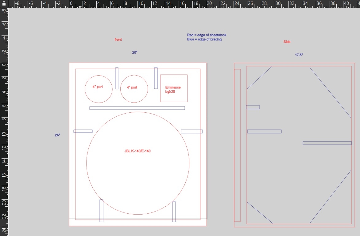
The layout and design are moving forward. Its one thing to think of a design, its another to put it in a scaled drawing. I tried some framing that would use lightweight techniques and found it would likely save 1/3 of a pound and be more complicated. In the end triangle "gusset" braces seem best. I also found that when laying out the baffle I had to change the outside dimensions to get everything to fit and not interfere with the grill. So, the internal dimensions had to be recalculated. Originally, I envisioned two triangle ports, but had to admit there's calculations that I am not knowledgeable about. So, round ABS pipe ports seem my best option. To keep the air velocity around 17ms I used two 4" ports. The bracing should be 1.5 to 2 lbs. The braces will probably be epoxied in, because clamping difficult and PVA glue needs pressure. I'll Eminence BGH 25 later, but wanted a place for it.
- Feb 12, 2006
- 61,068
- 5
- 221,131
- Disclosures
- Development Engineer-Mesa Boogie, Development Engineer-Genzler (pedals), Product Support-Genz Benz
Length 4.63" with .76 end correction. Yeah! I keep thinking they are too big, but going to 3" ports gives higher port air velocity. Here's the port air velocity graphs from WinISD. I'm tuning to 48 hz and modeling 125 watts, about the max for the questionable 3.6mm stated Xmax. The green and blue lines are 4" ports tuning 48hz and 50hz. My assumption is 17-18 (ms) is the target.Off the top of my head, that seems to be awfully large for the ports… what's the length?
Good thing this is all digital and no wood has been destroyed yet.
- Feb 12, 2006
- 61,068
- 5
- 221,131
- Disclosures
- Development Engineer-Mesa Boogie, Development Engineer-Genzler (pedals), Product Support-Genz Benz
You might want to verify that you input the TS parameters correctly, this doesn't look correct, especially at 125 watts.
Can you post the amplitude transfer function?
Can you post the amplitude transfer function?


