
Do they really in pickups? I know there can be issues in older speakers used hard and gotten hot, but I don't recall mere proximity being an issue. Happy to be wrong, and better to be safe than sorry and all that.AlNiCo magnets, however, can be easily de/re-magnetized, so it's probably best to keep pickups with those separated.

Enjoy the benefits of a premium membership!
Upgrade Account
-
TalkBass has been independent since 1998. Add your voice.
Create a free account to reply to discussions, view embedded media, and browse with fewer display ads.
Join free Log in
Want zero display ads or expanded classifieds tools? Compare plans.
You are using an out of date browser. It may not display this or other websites correctly.
You should upgrade or use an alternative browser.
You should upgrade or use an alternative browser.
Magnets & Copper Wire: A Pickup Building Thread
- Thread starter Freekmagnet
- Start date
More options
Who Replied?
slowburnaz
Commercial User
Do they really in pickups? I know there can be issues in older speakers used hard and gotten hot, but I don't recall mere proximity being an issue. Happy to be wrong, and better to be safe than sorry and all that.
Well, let's just say I play it safe.

I imagine that if you keep Alnico pickups close with polarity aligned, it might not be a huge issue. But I definitely wouldn't keep pickups loaded with C8s or Neos close to any Alnico pickups... and by close, I mean packed together in a drawer or something.

Related:
If the magnets are weaker, the pickup could be placed closer to the strings (to highlight the effect of that for someone wanting that, but not close enough to trigger the bad stuff).
I've never read a pickup ad saying that the magnets are not fully charged, like that.
If the magnets are weaker, the pickup could be placed closer to the strings (to highlight the effect of that for someone wanting that, but not close enough to trigger the bad stuff).
I've never read a pickup ad saying that the magnets are not fully charged, like that.
With a field strength meter, one should be able to invent a procedure for adjusting the charge of an alnico magnet using a neo.
Sorry, I have no experience with this.
Sorry, I have no experience with this.

Some pickup makers play around with adjusting the field strength of their Alnico magnets. Mostly the guys who are trying to make really accurate replicas of vintage pickups. They do the charging/decharging using a strong metal vise fitted with strong Neo magnets; passing the magnets through it. Or they build an electric magnetizer. An arc welder with an open transformer, effectively. Somewhat dangerous.
Most of us don't mess around with the field strength. Alnico magnets from a good supplier are usually charged consistently to the specs. I always check them by clicking something steel against them, to make sure they have approximately full and equal power. Just by feel; I don't bother trying to measure them with a gaussmeter. I haven't yet received a dead or weak one in supplies of new magnets, but I have seen a few dead ones in old used pickups.
Storage:
The Alnico magnets come through from the suppliers stuck together in a block, with a thin steel sheet wrapped around them. I assume that's a good way to store them, so I keep them like that. Just pull magnets out of the block as I need them.
As I'm assembling bobbins and magnets, I have a long steel bar on the bench. I stick the bobbins on there, maybe 2 inches apart. It holds them safely, so they don't get damaged by slamming together.
As I wind and terminate the bobbins, I stick them back on the bar. Mostly for mechanical protection.
Most of us don't mess around with the field strength. Alnico magnets from a good supplier are usually charged consistently to the specs. I always check them by clicking something steel against them, to make sure they have approximately full and equal power. Just by feel; I don't bother trying to measure them with a gaussmeter. I haven't yet received a dead or weak one in supplies of new magnets, but I have seen a few dead ones in old used pickups.
Storage:
The Alnico magnets come through from the suppliers stuck together in a block, with a thin steel sheet wrapped around them. I assume that's a good way to store them, so I keep them like that. Just pull magnets out of the block as I need them.
As I'm assembling bobbins and magnets, I have a long steel bar on the bench. I stick the bobbins on there, maybe 2 inches apart. It holds them safely, so they don't get damaged by slamming together.
As I wind and terminate the bobbins, I stick them back on the bar. Mostly for mechanical protection.
Last edited:

Been sorta trying to figure a good way of ditching tone and volume for some time
My first , go the p 90 is adjustable on the fly
Two channels made to slide , switch up its 2 neck pickups switch down is two bridges and the bridge
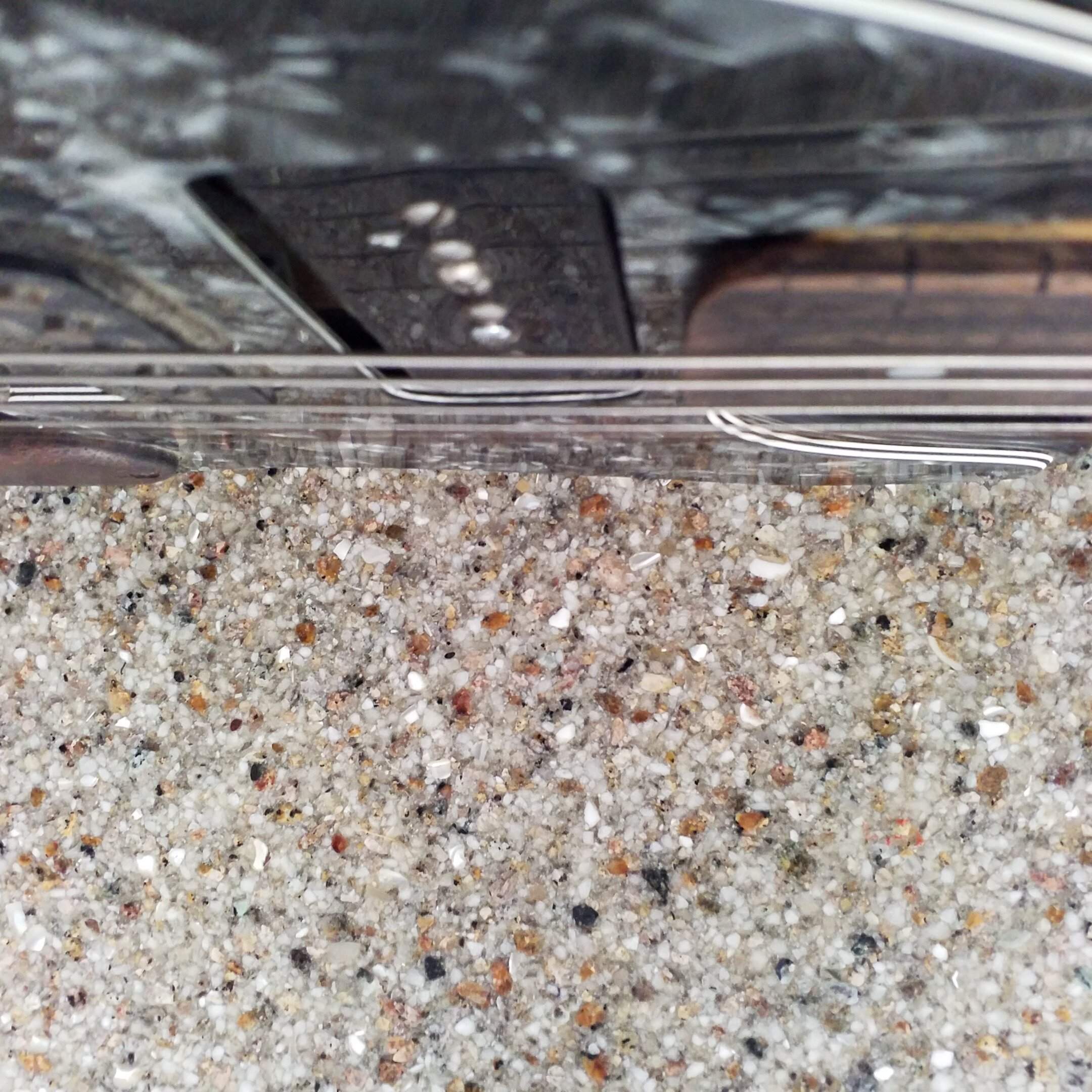
My first , go the p 90 is adjustable on the fly
Two channels made to slide , switch up its 2 neck pickups switch down is two bridges and the bridge
Attachments


Last edited:
Been sorta trying to figure a good way of ditching tone and volume for some time
My first , go the p 90 is adjustable on the fly
Two channels made to slide , switch up its 2 neck pickups switch down is two bridges and the bridge
View attachment 4697243
Well, that's interesting. So, you're making the pickups move vertically on slides? How are you moving them? A knob or lever?
It's got a interesting spring its a weird double helix? It can compress really thin ,Well, that's interesting. So, you're making the pickups move vertically on slides? How are you moving them? A knob or lever?
It hinges on strings. Hogged out the back with a router that rode wedges going 0 to .5 inch
Hard part was keeping it quiet I thought I had it quiet originally now it's kinda noisy .
Going straight into a tube amp you can really get a nice natural overdrive to a clean sound easily ,
one thing I learned is it really doesn't make any difference when using pedals.
If I made another I would do it differently, possibly with a Whammy thumb rest?
Last edited:

How do you find fretless guitar?Been sorta trying to figure a good way of ditching tone and volume for some time
My first , go the p 90 is adjustable on the fly
Two channels made to slide , switch up its 2 neck pickups switch down is two bridges and the bridge
View attachment 4697243
I pulled the frets, sawdust and CA glue , many years back all I played was slideHow do you find fretless guitar?
its really difficult to make a Fretless guitar sound good .
It really doesn't look like it but it was my tribute to the first electric guitar (fryingpan)
Mechanical effects make it less predictable and a little more interesting
Thing with slide, dynamics are a bit different, this moving pickup wouldn't fare to well on a bass
Last edited:
This week, I've been making up some pickup tooling for Jeremy (they call him Mr. Freekmagnet). One of his new bass designs gets cool triple pickups, and he needs the tooling and molds to cast the special lower bobbin halves. He decided to make them by the casting method, similar to the way I make all my bobbins. Machined aluminum Masters, silicone rubber molds, cast the parts in polyurethane resin. I offered to let him do the machining himself in my shop, under my close guidance, but he chickened out and decided to just pay me to make them up for him.
Jeremy's learning to run my machine tools, but he's still new at it. He's doing well making truss rod parts with the lathes and drill presses. But not quite ready to try serious milling machine jobs.
This job calls for machining up three custom aluminum Masters, and making up the silicone mold sets from them. These three bobbins are for the Bridge, Middle and Neck pickups of his new Pistolera model bass. The three bobbins are the same in design and main dimensions, but with slightly different spacing of the 3/8" magnets. The holes in the bobbins need to be accurately spaced and true vertically. He's going to be using laser-cut Forbon top plates for these bobbins.
I forgot to take pictures of the early steps, but I started off by sawing off three 2 1/2" lengths of 1 1/2" square 6061 aluminum bar stock. I clamped them in the big Kondia mill and milled the ends of the blocks square and flat and to equal length.
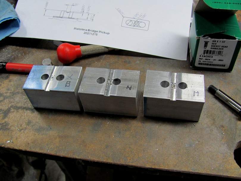
Then I set up the blocks in my green Mill/Drill machine, and milled a cross-wise clearance slot. Then accurately drilled the 3/8" holes where the magnets go, down through the blocks. You are just seeing the big 3/8" drill here, but each hole is first located with a spotting drill, and drilled through with a small pilot drill. We're trying to get reasonable accuracy here; +/- 0.002" location.
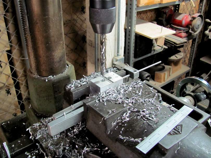
Here are the blocks with the magnet holes and terminal slots done. They are almost the same, just a slight difference in the positions of the magnet holes. One of Jeremy's CAD drawings is in the background. That's what I'm working from. The 3/8" x 1 1/2" Shoulder Bolts will become the precise plugs in the silicone molds.
Over to the big 'ol Kondia for the heavy milling. It's nice to have a big strong milling machine nearby.
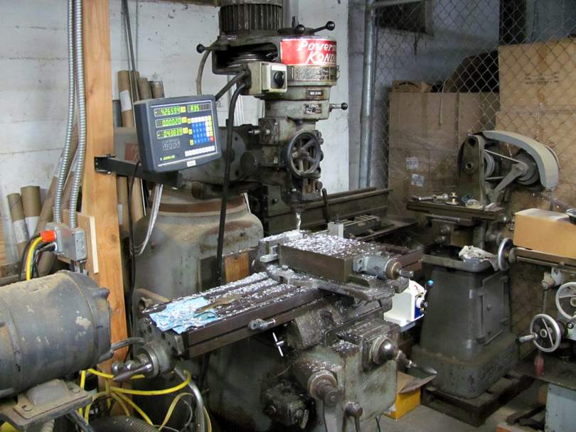
With a nice sharp 3/4" end mill and power feed on the table, it makes quick work of hogging off the extra aluminum. I start by milling along the front and back to make the center raised section.
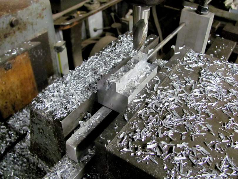
Then squaring off the ends, leaving half of the magnet holes. Then milling around the base, leaving a 1/16" thick flange. All to the dimensions on the drawings. This is what milling machines are for.
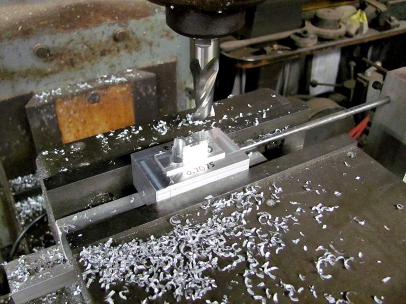
Here's what the bobbin looks like, Jeremy's design. It's a lower flange with a center section of plastic that fills the space between the two magnets and contains the terminals. The Forbon top plate will snap onto the top of the magnets. It should work well; compact and easy to manufacture.
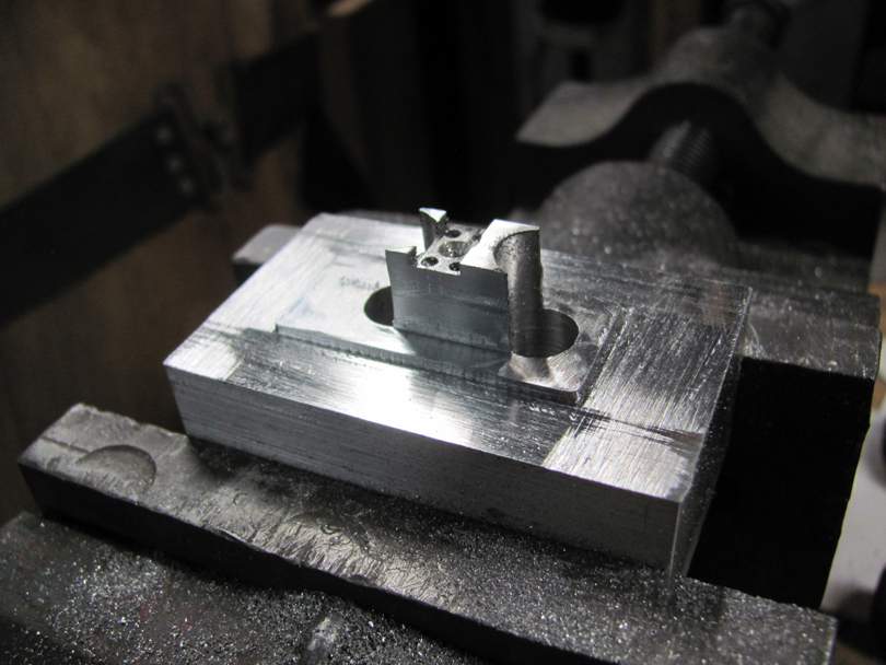
I spent a little time carefully filing each Master, smoothing the surfaces, putting small radiuses on the corners of the flange, etc. The Master doesn't have to be perfectly smooth, but it needs to be dimensionally accurate.
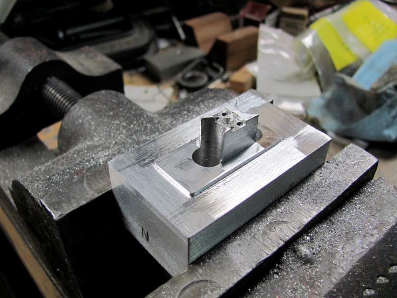
It's time to make the molds! I made up a triple box of MDF strips and blocks that fit nicely together. The inner surfaces are waxed with good 'ol Johnson's Paste Wax.
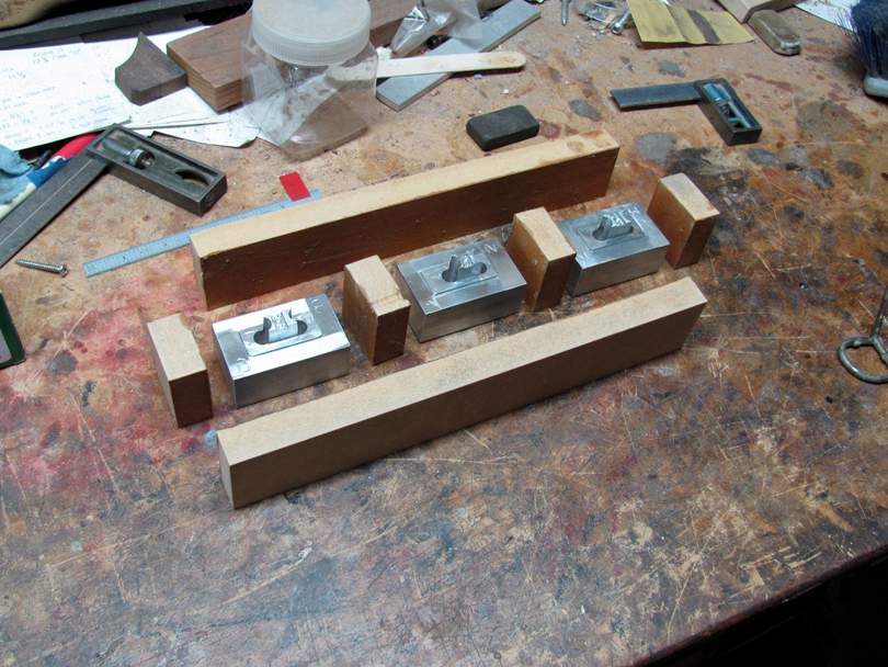
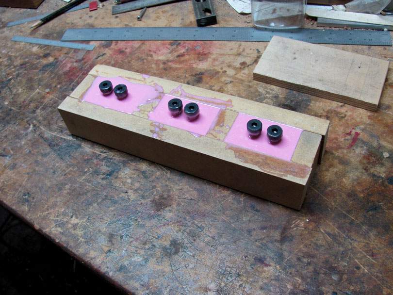
Here's the setup: The MDF box is all clamped around the Masters. The shoulder bolts are waxed and set down in the magnet holes.....
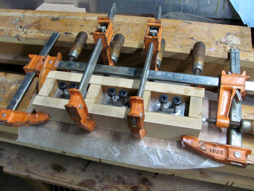
And I pour in the silicone rubber. I like Smooth-On's Easy Cast 30 Silicone Rubber Molding Compound. It's kind of slow drying, about 24 hours. But it works very well. Most of the air bubbles work up to the surface by themselves. I haven't found the need to use a vacuum chamber yet.
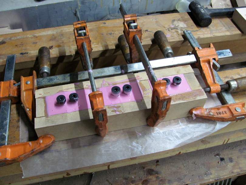
We'll see how they are doing tomorrow night.
Jeremy's learning to run my machine tools, but he's still new at it. He's doing well making truss rod parts with the lathes and drill presses. But not quite ready to try serious milling machine jobs.
This job calls for machining up three custom aluminum Masters, and making up the silicone mold sets from them. These three bobbins are for the Bridge, Middle and Neck pickups of his new Pistolera model bass. The three bobbins are the same in design and main dimensions, but with slightly different spacing of the 3/8" magnets. The holes in the bobbins need to be accurately spaced and true vertically. He's going to be using laser-cut Forbon top plates for these bobbins.
I forgot to take pictures of the early steps, but I started off by sawing off three 2 1/2" lengths of 1 1/2" square 6061 aluminum bar stock. I clamped them in the big Kondia mill and milled the ends of the blocks square and flat and to equal length.
Then I set up the blocks in my green Mill/Drill machine, and milled a cross-wise clearance slot. Then accurately drilled the 3/8" holes where the magnets go, down through the blocks. You are just seeing the big 3/8" drill here, but each hole is first located with a spotting drill, and drilled through with a small pilot drill. We're trying to get reasonable accuracy here; +/- 0.002" location.
Here are the blocks with the magnet holes and terminal slots done. They are almost the same, just a slight difference in the positions of the magnet holes. One of Jeremy's CAD drawings is in the background. That's what I'm working from. The 3/8" x 1 1/2" Shoulder Bolts will become the precise plugs in the silicone molds.
Over to the big 'ol Kondia for the heavy milling. It's nice to have a big strong milling machine nearby.
With a nice sharp 3/4" end mill and power feed on the table, it makes quick work of hogging off the extra aluminum. I start by milling along the front and back to make the center raised section.
Then squaring off the ends, leaving half of the magnet holes. Then milling around the base, leaving a 1/16" thick flange. All to the dimensions on the drawings. This is what milling machines are for.
Here's what the bobbin looks like, Jeremy's design. It's a lower flange with a center section of plastic that fills the space between the two magnets and contains the terminals. The Forbon top plate will snap onto the top of the magnets. It should work well; compact and easy to manufacture.
I spent a little time carefully filing each Master, smoothing the surfaces, putting small radiuses on the corners of the flange, etc. The Master doesn't have to be perfectly smooth, but it needs to be dimensionally accurate.
It's time to make the molds! I made up a triple box of MDF strips and blocks that fit nicely together. The inner surfaces are waxed with good 'ol Johnson's Paste Wax.
Here's the setup: The MDF box is all clamped around the Masters. The shoulder bolts are waxed and set down in the magnet holes.....
And I pour in the silicone rubber. I like Smooth-On's Easy Cast 30 Silicone Rubber Molding Compound. It's kind of slow drying, about 24 hours. But it works very well. Most of the air bubbles work up to the surface by themselves. I haven't found the need to use a vacuum chamber yet.
We'll see how they are doing tomorrow night.
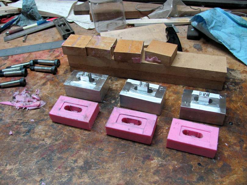
The silicone rubber is cured on Jeremy's pickup bobbin molds!
I sliced the seams with a sharp knife, pulled off the wood blocks, and pulled the three molds off of the Masters....
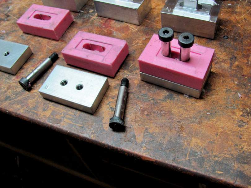
Each mold gets an aluminum base plate, cut from 1/2" x 1 1/2" bar stock. The three base plates are drilled and tapped 5/16-18 for the shoulder screws to thread into. The holes were drilled on the mill, at the exact spacing to match the three Masters. And this is how they go together. The ground shoulders of the screws fit tightly down through the silicone molds and thread into the bases. Tightened down, they are accurately spaced and perpendicular. They become part of the mold when the resin is poured in. The bobbins will end up with precise holes that the magnets will be a sliding fit in.
Here's the complete tooling set for Jeremy. One set of molds, the Masters, and the blocking. If he wants to make up more molds, he can assemble the blocking around the Masters and pour some more.
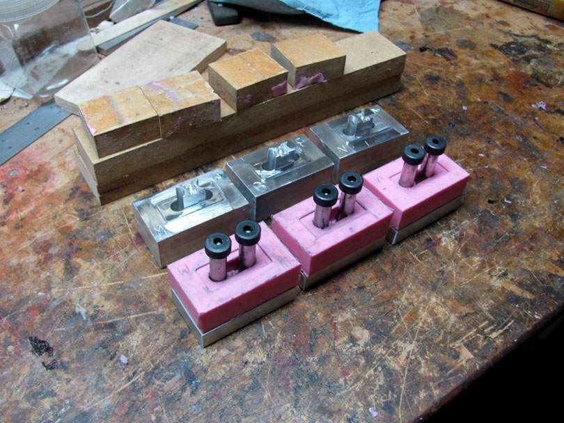
Just for your reference, this was not a whole lot of work....If you have a few machines. I charged Jeremy for 4 hours of labor and materials.
This method of using the shoulder bolts in the molds works very well for making cast resin bobbins. I use it on my production model pickups now. A big labor saver.
I sliced the seams with a sharp knife, pulled off the wood blocks, and pulled the three molds off of the Masters....
Each mold gets an aluminum base plate, cut from 1/2" x 1 1/2" bar stock. The three base plates are drilled and tapped 5/16-18 for the shoulder screws to thread into. The holes were drilled on the mill, at the exact spacing to match the three Masters. And this is how they go together. The ground shoulders of the screws fit tightly down through the silicone molds and thread into the bases. Tightened down, they are accurately spaced and perpendicular. They become part of the mold when the resin is poured in. The bobbins will end up with precise holes that the magnets will be a sliding fit in.
Here's the complete tooling set for Jeremy. One set of molds, the Masters, and the blocking. If he wants to make up more molds, he can assemble the blocking around the Masters and pour some more.
Just for your reference, this was not a whole lot of work....If you have a few machines. I charged Jeremy for 4 hours of labor and materials.
This method of using the shoulder bolts in the molds works very well for making cast resin bobbins. I use it on my production model pickups now. A big labor saver.

I am a little concerned that our respective notions of what constitutes "a few machines" might diverge a bit.Just for your reference, this was not a whole lot of work....If you have a few machines.


"a few machines" :I am a little concerned that our respective notions of what constitutes "a few machines" might diverge a bit.

You only need a few machines if they are big enough.I am a little concerned that our respective notions of what constitutes "a few machines" might diverge a bit.
AND has digital metering devices. NIIICE stuff indeed.
I am a little concerned that our respective notions of what constitutes "a few machines" might diverge a bit.
You could make up a tooling set like this with just a drill press and hand tools (hacksaw, files, tap handle, etc.).
I like to machine up the Masters from aluminum, to make them more permanent. And I have the machines and enjoy doing it. But Masters can be made from almost anything. The silicone rubber doesn't care. These masters could have been made from a block of hardwood, with the little bobbin part built up from pieces of styrene plastic and model glue. Shaped with Xacto knives and files. Like how we used to make model cars. That would work just fine for the Masters. They can even be made by carving blocks of wax or modeling clay.
You only need a few machines if they are big enough.
AND has digital metering devices. NIIICE stuff indeed.
Only if you are making the Masters from metal. And you don't need digital readouts to make parts to accurate tight dimensions. Rulers, calipers and micrometers are just as accurate as they've always been. I've only recently put digital readouts on two of my milling machines. They make things faster, but I was machining accurate parts before I got them.
"a few machines" :

Yep, that's my dream shop. I'm in the process right now of acquiring another shop space in the building here, next to my current spaces. It's going to be my antique machine shop, filled with my collection of pre-1940 machines. That picture is the model of how I want this shop to look and feel. 1930's technology. Not a static museum display. All the machines running and useable. And I can go in there and use them to make musical instrument parts. Whenever I feel like it.
My main machine shop will stay about like it is; 1945-1980's technology. A few digital readouts. Maybe I'll eventually get one 1990's era CNC turret mill.

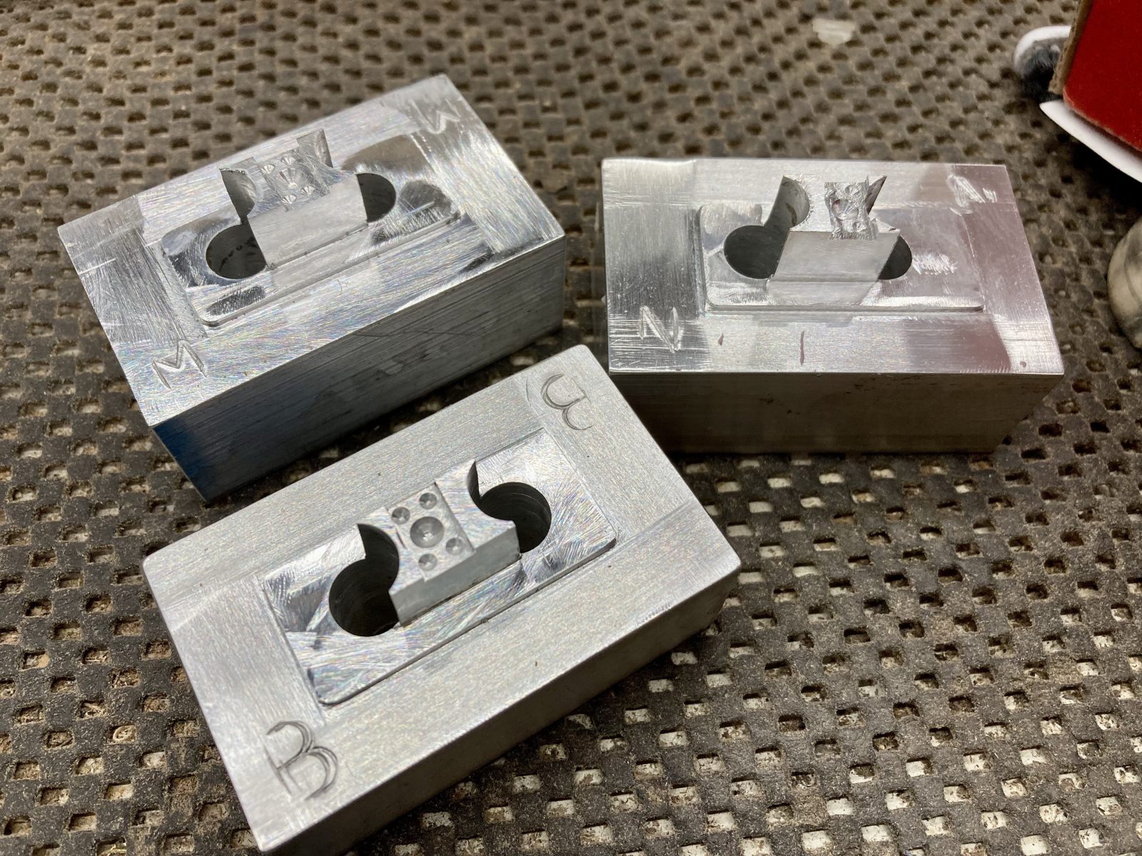
I haven't had any earth shattering news about the Pistolera for a while, but this week, Mr. Bruce made some pickup masters and molds for me. There's a neck, middle and bridge pickup, so I needed 3 masters. Here's the masters he machined out of aluminum:
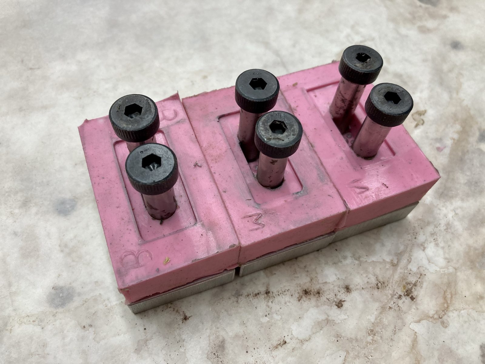
From those, he made molds with shoulder bolts. These are awesome. Thanks @Bruce Johnson!
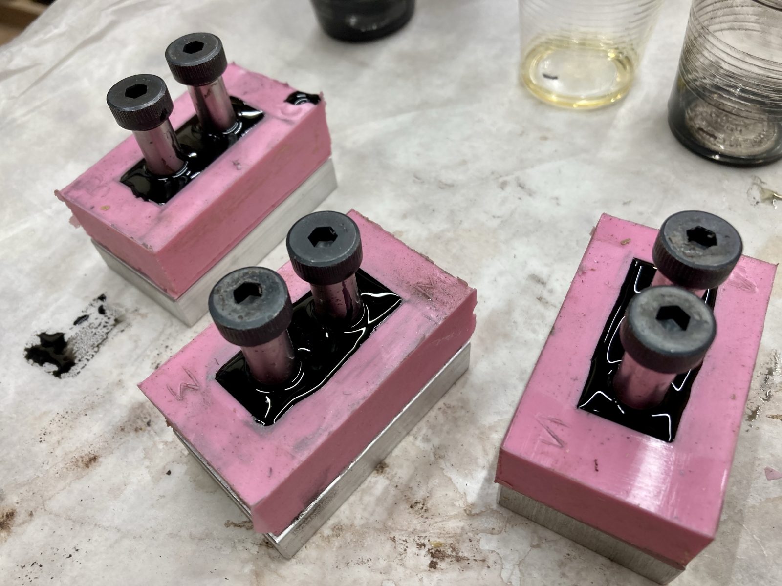
Next, I spent an afternoon making some bobbin halves out of cast polyurethane.
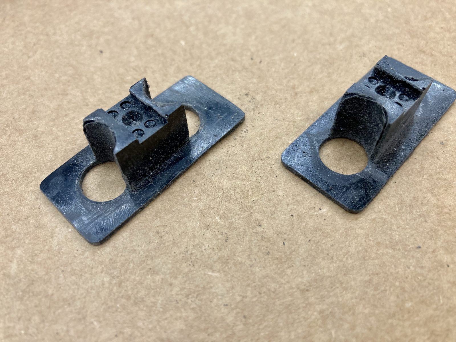
Once these were popped out of the molds, they had to be cleaned up. That was a somewhat simple matter of hitting them with the belt sander and filing the edges down.
Here I am drilling holes for the wires and for the assembly and winding process:
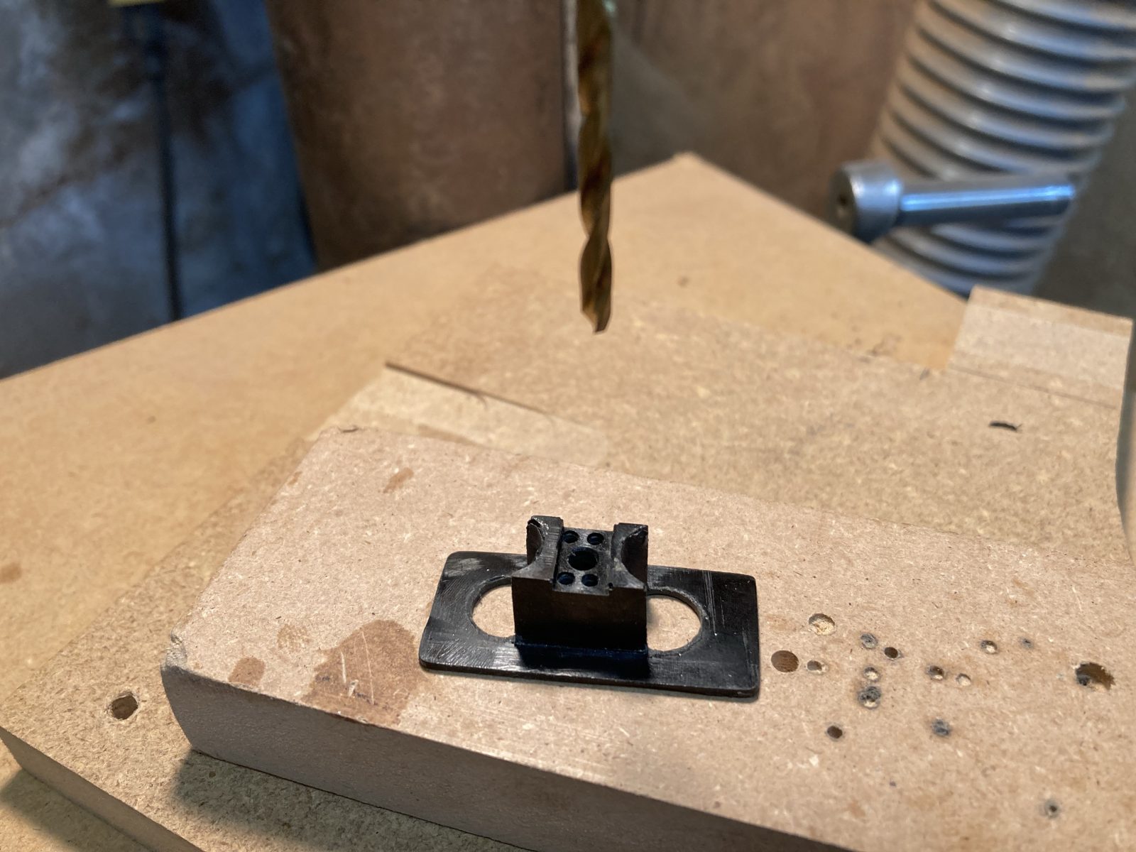
The bobbins are a pretty simple design. They're basically the cast half, the magnets and a laser-cut piece of flatwork. Despite their simplicity, it took me a whole afternoon to get a pair of functioning prototypes.
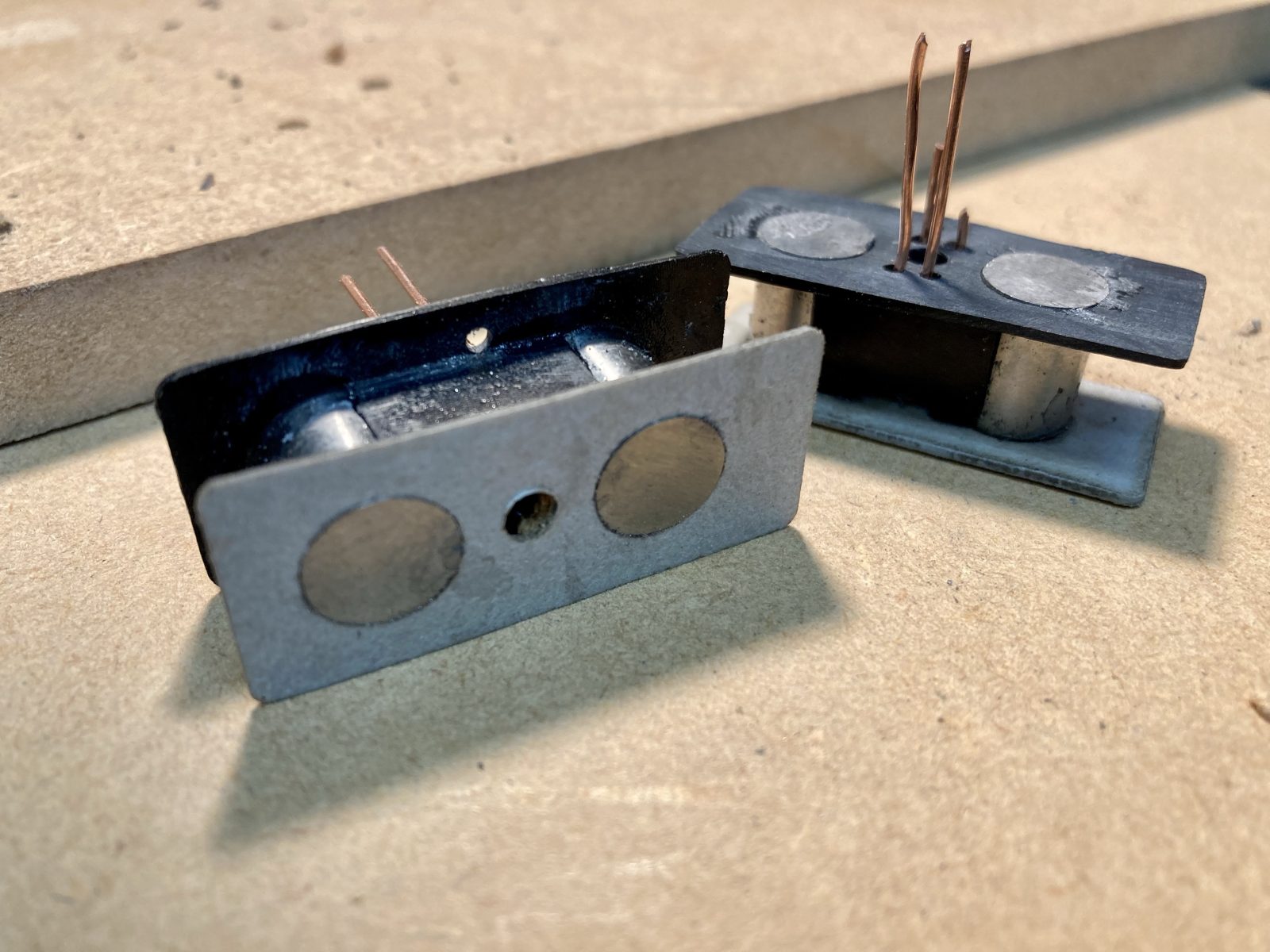
And here's a couple shots of the whole magnetic assembly. I made a steel inductance plate that goes underneath the bobbins.
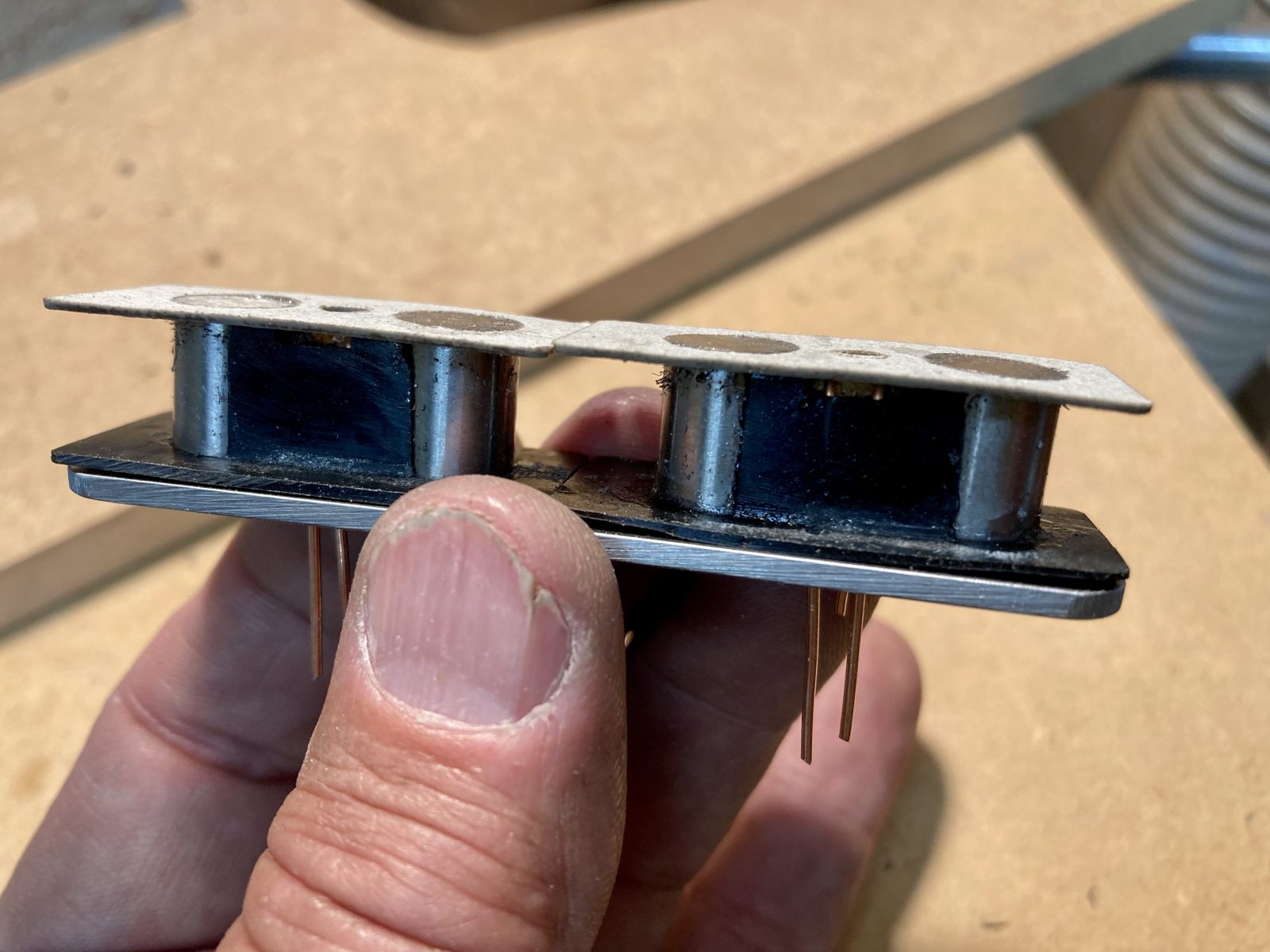
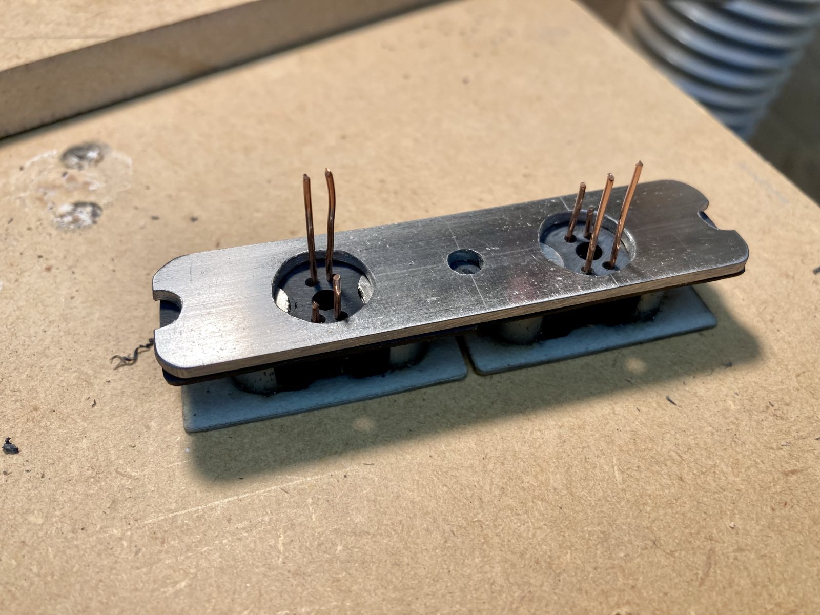
I actually have to go down to the shop this afternoon and make a new baseplate. The design called for a 1/8" plate, and I accidentally grabbed a piece of 2mm steel bar. I went home and did some more tests, and the pickup really wants the 1/8" plate.
I may start winding this pickup tonight. I'll see how things shape up later today.
From those, he made molds with shoulder bolts. These are awesome. Thanks @Bruce Johnson!
Next, I spent an afternoon making some bobbin halves out of cast polyurethane.
Once these were popped out of the molds, they had to be cleaned up. That was a somewhat simple matter of hitting them with the belt sander and filing the edges down.
Here I am drilling holes for the wires and for the assembly and winding process:
The bobbins are a pretty simple design. They're basically the cast half, the magnets and a laser-cut piece of flatwork. Despite their simplicity, it took me a whole afternoon to get a pair of functioning prototypes.
And here's a couple shots of the whole magnetic assembly. I made a steel inductance plate that goes underneath the bobbins.
I actually have to go down to the shop this afternoon and make a new baseplate. The design called for a 1/8" plate, and I accidentally grabbed a piece of 2mm steel bar. I went home and did some more tests, and the pickup really wants the 1/8" plate.
I may start winding this pickup tonight. I'll see how things shape up later today.
I haven't had any earth shattering news about the Pistolera for a while, but this week, Mr. Bruce made some pickup masters and molds for me. There's a neck, middle and bridge pickup, so I needed 3 masters. Here's the masters he machined out of aluminum:
From those, he made molds with shoulder bolts. These are awesome. Thanks @Bruce Johnson!
Next, I spent an afternoon making some bobbin halves out of cast polyurethane.
Once these were popped out of the molds, they had to be cleaned up. That was a somewhat simple matter of hitting them with the belt sander and filing the edges down.
Here I am drilling holes for the wires and for the assembly and winding process:
The bobbins are a pretty simple design. They're basically the cast half, the magnets and a laser-cut piece of flatwork. Despite their simplicity, it took me a whole afternoon to get a pair of functioning prototypes.
And here's a couple shots of the whole magnetic assembly. I made a steel inductance plate that goes underneath the bobbins.
I actually have to go down to the shop this afternoon and make a new baseplate. The design called for a 1/8" plate, and I accidentally grabbed a piece of 2mm steel bar. I went home and did some more tests, and the pickup really wants the 1/8" plate.
I may start winding this pickup tonight. I'll see how things shape up later today.
Hmmm....Looking at the assembly of the bobbins with the Inductive Bar on them, I see a potential problem? How are you going to rout the ends of the magnet wire, to get them wrapped on the terminals, without them getting pinched under the Inductive Bar? That would be bad, having the steel bar pressing on the fragile wires. You may need to make a small groove on the top side of the cast part?


