

Enjoy the benefits of a premium membership!
Upgrade Account
-
TalkBass has been independent since 1998. Add your voice.
Create a free account to reply to discussions, view embedded media, and browse with fewer display ads.
Join free Log in
Want zero display ads or expanded classifieds tools? Compare plans.
You are using an out of date browser. It may not display this or other websites correctly.
You should upgrade or use an alternative browser.
You should upgrade or use an alternative browser.
Magnets & Copper Wire: A Pickup Building Thread
- Thread starter Freekmagnet
- Start date
More options
Who Replied?
Here's a housing mold set that I just completed for Jeremy. This is for casting the external shell of his Pistolera model pickups. He gave me an Acad drawing of the external shape and dimensions.
The first step is to make up a Master; an actual size final shape of the pickup. I like to machine the masters from aluminum for durability, but masters can be made from wood or plastic too. They just need to be accurate in dimensions and smoothly finished.
I start with a chunk of 1 1/2" square 6061 aluminum bar stock, sawn off to length. I use the big Kondia milling machine to hog off the excess aluminum and bring the rectangular pickup to size and shape.
View attachment 4789029
I leave a rectangular flange at the bottom, to help with casting the silicone mold.
View attachment 4789030
I forgot to photograph a couple of steps, but there's the finished master. I used my smaller mill to drill the holes for the screws all the way down through with a #30 bit. Small counterbores at the top to recess the screw heads. These holes and counterbores will be created accurately during the pickup casting process. He won't have to drill them after casting.
I hand filed small radiuses on the corners and edges, to his drawing, and block-sanded the flat surfaces to 400 grit. Jeremy said it wasn't necessary to go to a full polish on this one.
The part in the front is the base plate for the silicone mold. It holds the two pins in accurate position during the casting. The base plate is a piece of 1/4" x 1 1/2" aluminum bar stock. The hole locations are transfer punched from the master. The pins are cut from 1/8" steel rod stock, rounded on the ends.
View attachment 4789031
I ripped a strip of 3/4" MDF and cut it into four blocks that fit tightly into a box around that bottom flange of the master, like this.
View attachment 4789032
I waxed the faces of the MDF blocks and clamped them around the master, on a sheet of waxed paper. The pins are also waxed and inserted in the holes in the master. Then I mixed up the silicone mold making compound and poured it in the box, up to the top edge.
I like Smooth-On's Mold Max 30 silicone compound. It's kind of slow curing, about 12 hours, but bubbles work their way up and out in open air curing like this. For most things like this, it doesn't need to be put in a vacuum chamber. It's simple and reliable.
View attachment 4789033
The next day, I pulled the mold off of the master, no problem.
View attachment 4789034
Now I fit the pins into the base plate. I drilled those holes 1/8", so the pins are a light hammer-tap friction fit.
View attachment 4789035
The mold then slips down over the pins. The base plate holds the pins at an accurate dimensional spacing and straight vertical during the casting. You can see the little bump in the silicone around the pin that creates the counterbore.
View attachment 4789036
And here's the finished mold kit going to Jeremy. The master, the mold, and the wood blocks. This mold will probably be good for 50-100 pickups. When it wears out, he can easily pour a new mold using the master and the wood blocks.
View attachment 4789037
I'm showing all of you this to encourage you to try this for yourselves, for own pickup making projects. Don't be intimidated by my milling machines and aluminum masters. You can make the masters by gluing them up from blocks of maple or plastic, and hand filing them to shape. Pouring silicone molds and casting pickups in poly resin or epoxy is easy to do in a small shop.
The main thing I'm showing here is the trick of using the steel pins and aluminum base plate with the silicone mold, to make accurate screw holes in your castings. You can do that with a drill press.
Holy Cow! Thanks, Bruce!
Look what arrived in the post today
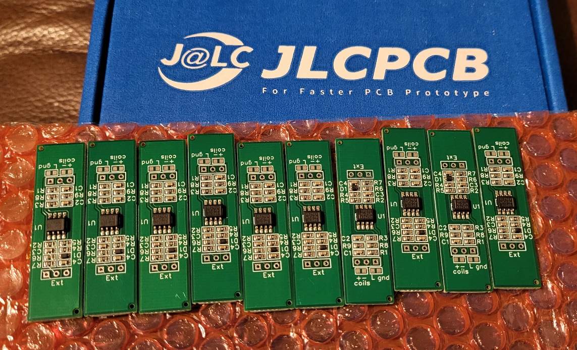
Active pickup PCBs. Based on the EMG81 with a few mods, not least a new opamp and input caps that suit a bass. My pickup winder is an ongoing project but will be done soon. Let's see how deep the rabbit hole goes.
Active pickup PCBs. Based on the EMG81 with a few mods, not least a new opamp and input caps that suit a bass. My pickup winder is an ongoing project but will be done soon. Let's see how deep the rabbit hole goes.


Throwing my hat in here,
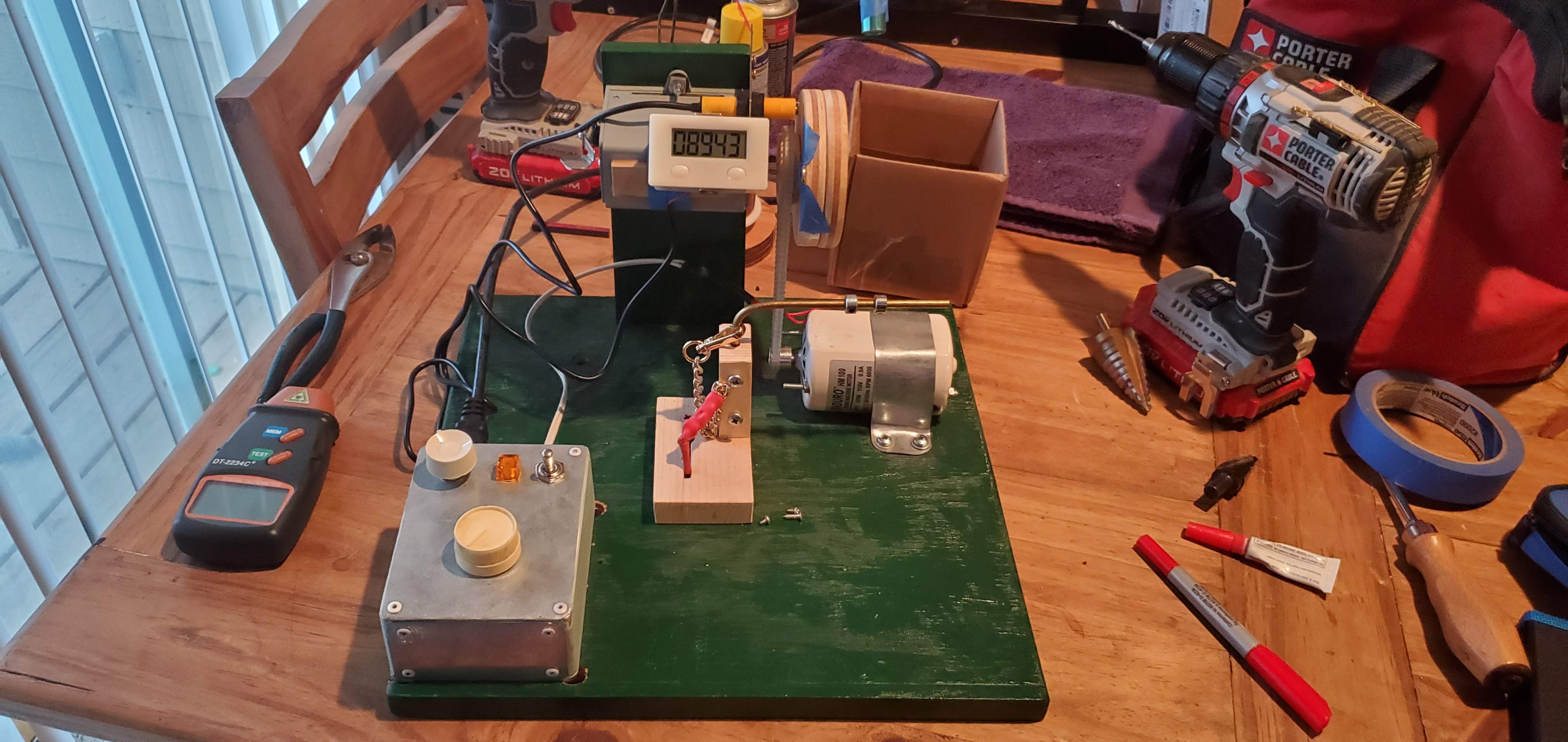
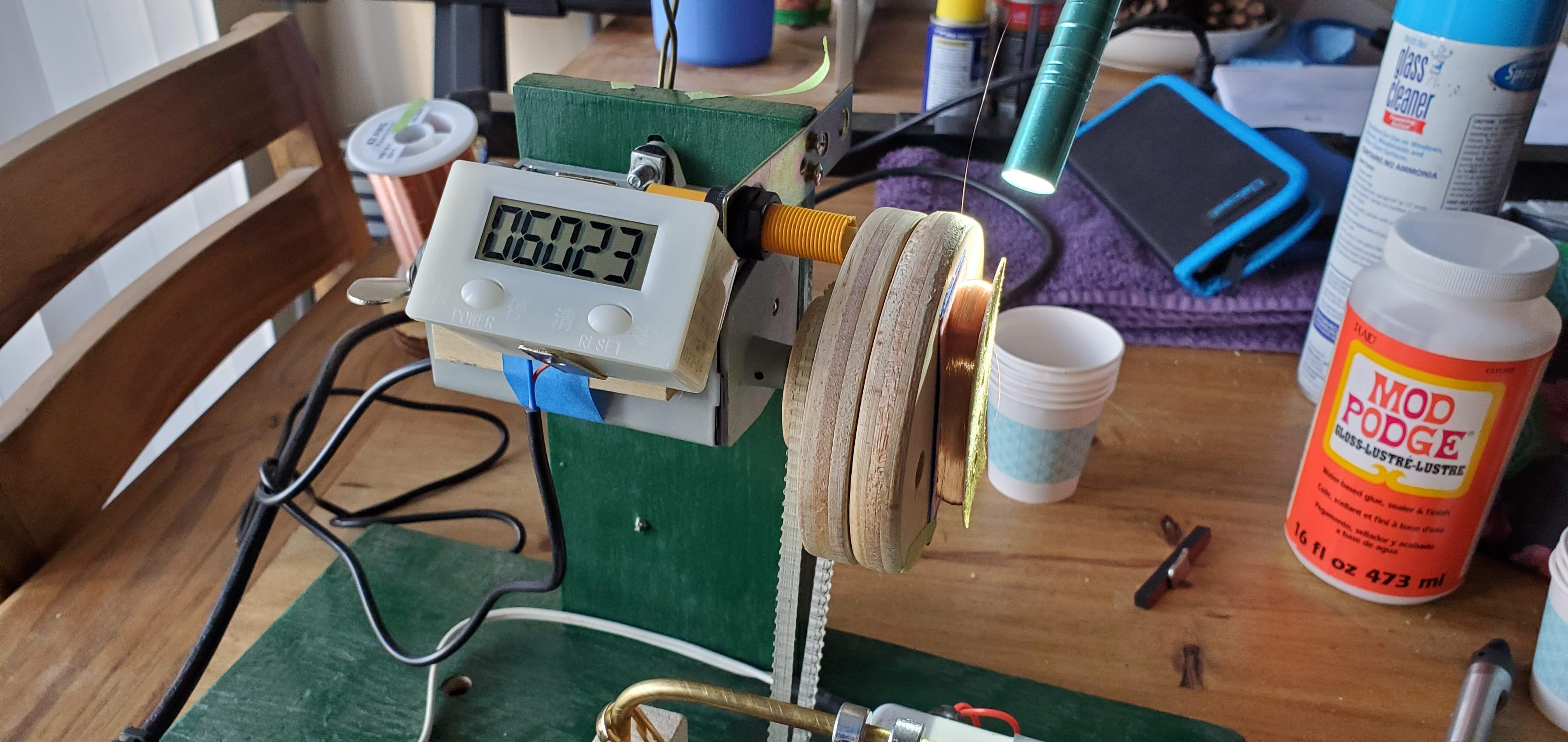
Just switched to a cheap mag counter here I had the magnet taped in place (I know I didn't sit in front of it like this lol.
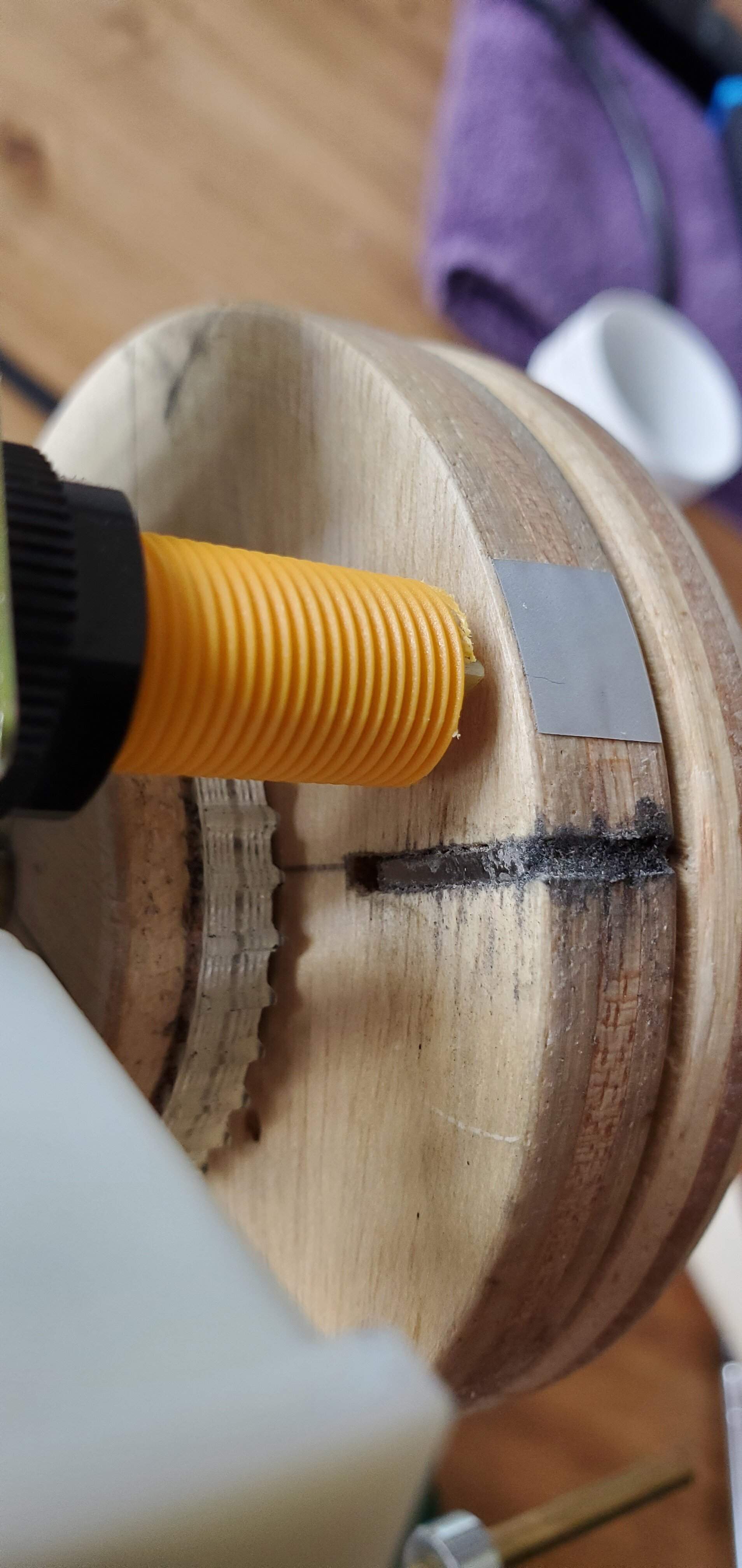
Ended up inlaying the magnet sideways because the counter at about 1450rpm freaks out and stops until you slow back down. I was hoping a narrower field would help, but it seems about the same. Also worth mentioning here, I trimmed the head of the cheap sensor that came with my counter that actually did gain me around a k or so of speed sensing.
Now I can wind all day long at 1350rpm and have no issues but I would definitely be open to suggestions as a little wiggle room say being able to wind at 2k and under would be ideal.
I guess the next step would be figuring out what makes this sensor tick? I know it is normally open and closes to about an ohm when passed over so it can't be too complicated.
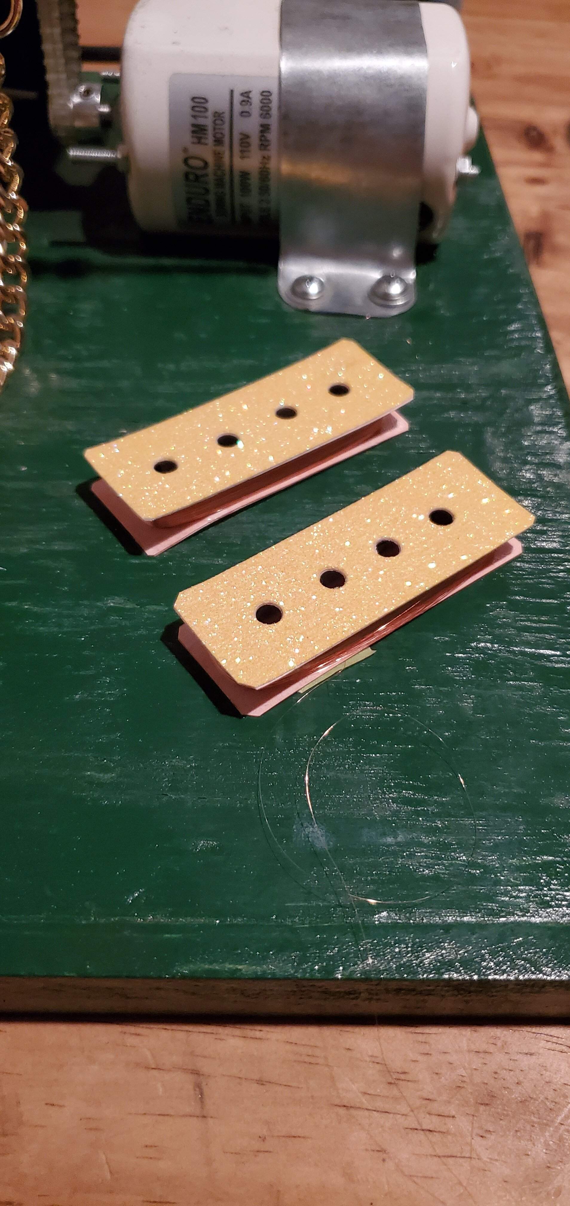
Bonus winding pics,
Just switched to a cheap mag counter here I had the magnet taped in place (I know I didn't sit in front of it like this lol.
Ended up inlaying the magnet sideways because the counter at about 1450rpm freaks out and stops until you slow back down. I was hoping a narrower field would help, but it seems about the same. Also worth mentioning here, I trimmed the head of the cheap sensor that came with my counter that actually did gain me around a k or so of speed sensing.
Now I can wind all day long at 1350rpm and have no issues but I would definitely be open to suggestions as a little wiggle room say being able to wind at 2k and under would be ideal.
I guess the next step would be figuring out what makes this sensor tick? I know it is normally open and closes to about an ohm when passed over so it can't be too complicated.
Bonus winding pics,

Now I can wind all day long at 1350rpm and have no issues but I would definitely be open to suggestions as a little wiggle room say being able to wind at 2k and under would be ideal.
Any cheap Arduino-compatible board with a hall effect sensor would work. Not sure how open you are to tinkering with microcontrollers though.
Throwing my hat in here,
View attachment 4819085
Just switched to a cheap mag counter here I had the magnet taped in place (I know I didn't sit in front of it like this lol.
View attachment 4819083
Ended up inlaying the magnet sideways because the counter at about 1450rpm freaks out and stops until you slow back down. I was hoping a narrower field would help, but it seems about the same. Also worth mentioning here, I trimmed the head of the cheap sensor that came with my counter that actually did gain me around a k or so of speed sensing.
Now I can wind all day long at 1350rpm and have no issues but I would definitely be open to suggestions as a little wiggle room say being able to wind at 2k and under would be ideal.
I guess the next step would be figuring out what makes this sensor tick? I know it is normally open and closes to about an ohm when passed over so it can't be too complicated.
Bonus winding pics,
View attachment 4819081
View attachment 4819084
2K RPM is kinda fast! I usually roll around 1K. I’m not saying 2K won’t work, but at 1450, you’re definitely in the right RPM range.
Nice work, BTW. Looks great!
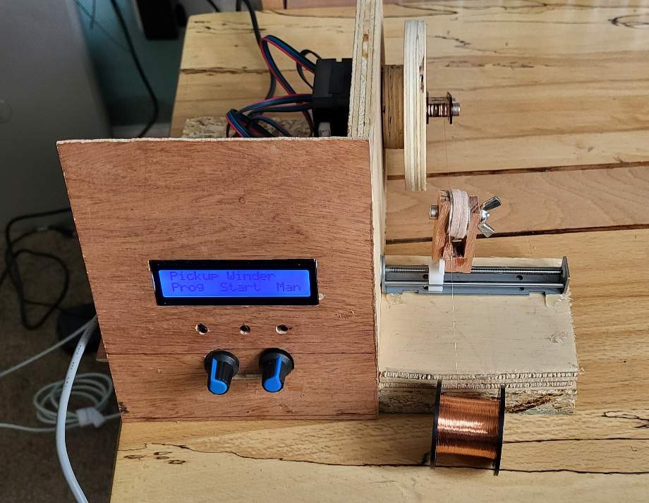
Disaster! This is my prototype pickup winder. I chose to use two stepper motors. One for the winder and one for the feeder. That way, the two can be kept in sync as the speed is varied, giving constant winds. The thought was that scatter wind patterns could be programmed in to it. The possibilities are endless. It turns out that the stepper motor doesn't have nearly enough oomph to unspool the wire off the drum. It just stalls. Back to the drawing board.
Disaster! This is my prototype pickup winder. I chose to use two stepper motors. One for the winder and one for the feeder. That way, the two can be kept in sync as the speed is varied, giving constant winds. The thought was that scatter wind patterns could be programmed in to it. The possibilities are endless. It turns out that the stepper motor doesn't have nearly enough oomph to unspool the wire off the drum. It just stalls. Back to the drawing board.
View attachment 4819609
The first thing I'd try is standing the spool on it's end.

Can you get a bigger stepper? You might need a different driver, but I've seen this done before.
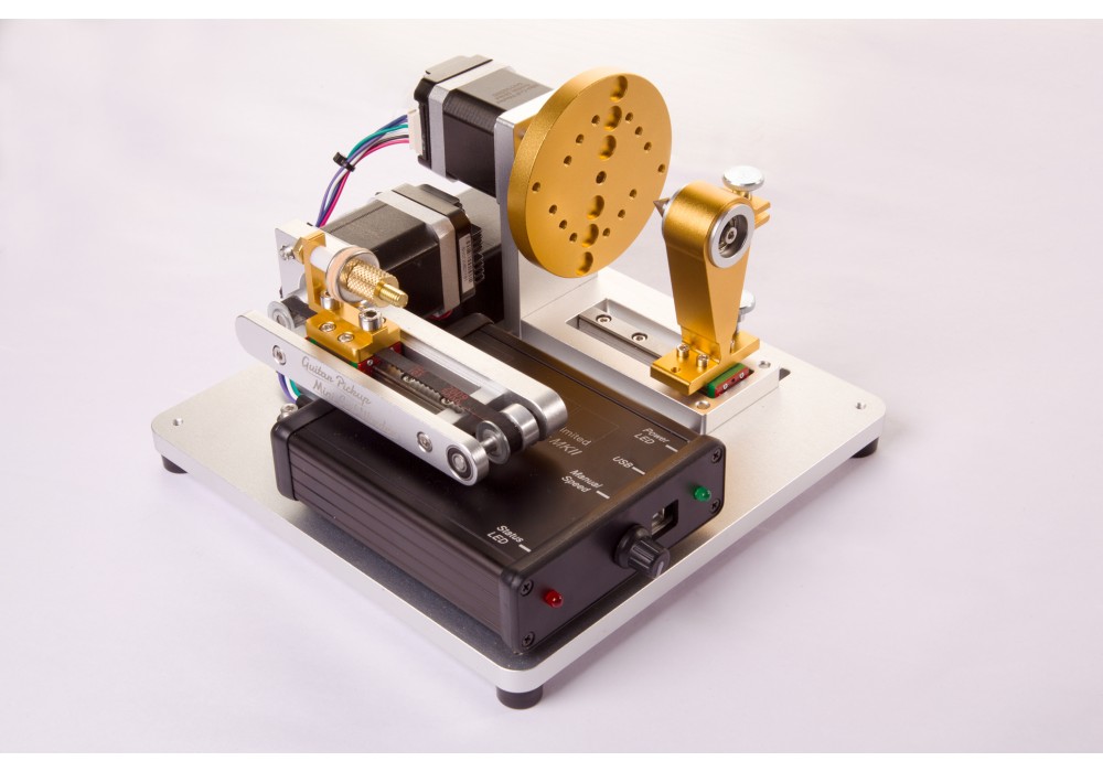
Another option is to use an optical trigger using a regular old electric motor. That's what I did. The key is to shield the heck out of the wires going to the LED and the phototransistor. Those steppers throw a lot of EM interference all over the place.
Yes, the drivers (and power supply) can supply a bit more current. There is a motor that can make 5x the torque from that current. I need to do some calculations to see if that's enough.
Otherwise I might need to go for a DC motor and driver, and just put up with the limited ability to sync the feeder to the winder.
Otherwise I might need to go for a DC motor and driver, and just put up with the limited ability to sync the feeder to the winder.
Yes, the drivers (and power supply) can supply a bit more current. There is a motor that can make 5x the torque from that current. I need to do some calculations to see if that's enough.
Otherwise I might need to go for a DC motor and driver, and just put up with the limited ability to sync the feeder to the winder.
You can sync the feeder to the winder with an optical trigger. Assuming you're using an Arduino controller, you'd have to write a different script. Using that approach does have it's limitations like you said, but it's easy to work around. I've thought about writing a "scatterwound" mode for my winder. I'm pretty sure it would work, but scatterwinding isn't really my thing.

Have you tried putting the wire spool on an axel, with bearings if needed?Disaster! This is my prototype pickup winder. I chose to use two stepper motors. One for the winder and one for the feeder. That way, the two can be kept in sync as the speed is varied, giving constant winds. The thought was that scatter wind patterns could be programmed in to it. The possibilities are endless. It turns out that the stepper motor doesn't have nearly enough oomph to unspool the wire off the drum. It just stalls. Back to the drawing board.
View attachment 4819609
Disaster! This is my prototype pickup winder. I chose to use two stepper motors. One for the winder and one for the feeder. That way, the two can be kept in sync as the speed is varied, giving constant winds. The thought was that scatter wind patterns could be programmed in to it. The possibilities are endless. It turns out that the stepper motor doesn't have nearly enough oomph to unspool the wire off the drum. It just stalls. Back to the drawing board.
View attachment 4819609
OK but...
You are supposed to despool the wire from the end of the spool so the spool itself doesn't actually move. See:
https://www.stewmac.com/globalasset...ickup-winding-with-the-schatten-pickup-winder
"Pickup wire isn’t meant to feed off a rotating spool. It’s too
thin to take the strain of turning the spool. Instead, let the
wire feed off the end of the spool vertically, about 3 or 4
feet below the winder."
thin to take the strain of turning the spool. Instead, let the
wire feed off the end of the spool vertically, about 3 or 4
feet below the winder."
My winder design also uses small steppers and has never had an issue stalling when feeding off the end of the spool. Hopefully that simple tip solves your issue!
I've tried putting the wire on the floor so it unspools axially. I've tried having it horizontally on an axis. If I manually unspool a long length of wire, it will wind it but the first 'tug' of the spool when the slack is taken up stalls it every time.
I've ordered a bigger motor off Amazon which should arrive tomorrow. With luck, that might be enough.
I've ordered a bigger motor off Amazon which should arrive tomorrow. With luck, that might be enough.
This.OK but...
You are supposed to despool the wire from the end of the spool so the spool itself doesn't actually move. See:
https://www.stewmac.com/globalasset...ickup-winding-with-the-schatten-pickup-winder
"Pickup wire isn’t meant to feed off a rotating spool. It’s too
thin to take the strain of turning the spool. Instead, let the
wire feed off the end of the spool vertically, about 3 or 4
feet below the winder."
My winder design also uses small steppers and has never had an issue stalling when feeding off the end of the spool. Hopefully that simple tip solves your issue!
Here's my highly advanced feed system if this helps.

Its more inline with the winder when winding but this'll give ya the idea. Notice it's setting on my starrett calipers case, this keeps it precise.

Attachments

This.
Here's my highly advanced feed system if this helps.
Its more inline with the winder when winding but this'll give ya the idea. Notice it's setting on my starrett calipers case, this keeps it precise.
Woah, that is pretty advanced!
Nice winder design. Great minds think alike it would seem.OK but...
You are supposed to despool the wire from the end of the spool so the spool itself doesn't actually move. See:
https://www.stewmac.com/globalasset...ickup-winding-with-the-schatten-pickup-winder
"Pickup wire isn’t meant to feed off a rotating spool. It’s too
thin to take the strain of turning the spool. Instead, let the
wire feed off the end of the spool vertically, about 3 or 4
feet below the winder."
My winder design also uses small steppers and has never had an issue stalling when feeding off the end of the spool. Hopefully that simple tip solves your issue!
my wire spool is about 3cm diameter and has been in the packet in my garage for 30 years. it's not sticky to unspool but it does need to be pulled rather than falling off under its own weight. I wonder if that's the difference?
Nice winder design. Great minds think alike it would seem.
my wire spool is about 3cm diameter and has been in the packet in my garage for 30 years. it's not sticky to unspool but it does need to be pulled rather than falling off under its own weight. I wonder if that's the difference?
Thanks!
I guess the wire could be a bit sticky, but I use a decent amount of tension (a few grams probably) in the tensioner on my machine, which is definitely more than the force required to despool. If you expect to run out of wire anytime soon, or if you want a gauge you don't already have, you could always buy a new spool of wire and compare it to the current one.
A couple of other thoughts:
- What driver are you using for your steppers? Most of the more advanced drivers have adjustable current and will support an amp or two. That should create enough torque, even on a NEMA 17, to pull on some pickup wire.
- How fast are you running your winder? Stepper motor torque drops with speed so the faster you go the lower the torque the motor will produce. Eventually it won't generate enough torque to overcome its own internal mechanical resistance and it will stall without anything attached to the shaft. In my case I designed for up to 500 RPM. Not blazing fast, but since it runs unattended speed isn't a large consideration.
Woah, that is pretty advanced!
You haven't seen anything yet. My feed system is a 5 gallon pail on the floor!
My stepper is good for 500 RPM. Above that it starts to skip. I'm using the same driver as you by the looks of it. I've turned it up to full current which is 2A I believe. It will wind but not despool. I'll have another go at a lower speed. In any case the new motor will arrive tomorrow. Lets see what that can do.Thanks!
I guess the wire could be a bit sticky, but I use a decent amount of tension (a few grams probably) in the tensioner on my machine, which is definitely more than the force required to despool. If you expect to run out of wire anytime soon, or if you want a gauge you don't already have, you could always buy a new spool of wire and compare it to the current one.
A couple of other thoughts:
- What driver are you using for your steppers? Most of the more advanced drivers have adjustable current and will support an amp or two. That should create enough torque, even on a NEMA 17, to pull on some pickup wire.
- How fast are you running your winder? Stepper motor torque drops with speed so the faster you go the lower the torque the motor will produce. Eventually it won't generate enough torque to overcome its own internal mechanical resistance and it will stall without anything attached to the shaft. In my case I designed for up to 500 RPM. Not blazing fast, but since it runs unattended speed isn't a large consideration.
I might try some newer wire. The stuff I have is 44 SWG which is about 39.5 AWG. "thick" stuff.

Yes, I'll confirm what the others are saying: You must unreel magnet wire off of the end of the spool! Do not try to unreel the wire off the side of the spool, spinning the spool on an axle. That doesn't work.
At the factory, the wire is wound onto the spool from the end. This puts a twist into the wire as it's on the spool. As you unreel it from the end, it untwists to a neutral state.
If you try to unreel from the side, it will come off twisted, continuing to twist with every rotation of the spool. After a few feet, the wire will kink and knot and snap.
I learned this the hard way when I was building my winder. I actually built a nice free-rolling axle thing for my wire spool, and tried to unreel the wire from the side. It absolutely did not work. The wire would jam up and snap every few feet. I eventually figured it out.
The basic rule is to position the spool so that the axle through the center is pointing right at the bobbin. You want the wire to unreel off the end of the spool in a nearly straight path to your tensioner and onto the bobbin. Minimal bends and turns.
It should be almost zero drag pulling the wire off of the spool. Your spindle motor should only be seeing the wire tension that you set with your tensioner. Usually 20-25gm.
Edit: You can see my machine back on Page 1 of this thread, Post #16. My wire is on large 4 lb spools. I have the spool mounted back behind the winder, tilted a little above horizontal. The axis points just below the bobbin. The wire feeds straight off the end of the spool, through the tensioner, and around a black Delrin feed wheel, onto the bobbin.
This system has been very reliable for more than 15 years of making pickups. I control the tension right at 25gm, and I very rarely break any wire.
At the factory, the wire is wound onto the spool from the end. This puts a twist into the wire as it's on the spool. As you unreel it from the end, it untwists to a neutral state.
If you try to unreel from the side, it will come off twisted, continuing to twist with every rotation of the spool. After a few feet, the wire will kink and knot and snap.
I learned this the hard way when I was building my winder. I actually built a nice free-rolling axle thing for my wire spool, and tried to unreel the wire from the side. It absolutely did not work. The wire would jam up and snap every few feet. I eventually figured it out.
The basic rule is to position the spool so that the axle through the center is pointing right at the bobbin. You want the wire to unreel off the end of the spool in a nearly straight path to your tensioner and onto the bobbin. Minimal bends and turns.
It should be almost zero drag pulling the wire off of the spool. Your spindle motor should only be seeing the wire tension that you set with your tensioner. Usually 20-25gm.
Edit: You can see my machine back on Page 1 of this thread, Post #16. My wire is on large 4 lb spools. I have the spool mounted back behind the winder, tilted a little above horizontal. The axis points just below the bobbin. The wire feeds straight off the end of the spool, through the tensioner, and around a black Delrin feed wheel, onto the bobbin.
This system has been very reliable for more than 15 years of making pickups. I control the tension right at 25gm, and I very rarely break any wire.
Last edited:


