Confirmed - it is an unspooling problem. I unwound 100 turns worth of wire and wound it round my finger. The winder turned it onto the bobbin nicely. The problem is with the rim of the spool of wire. The wire won't slide round the rim. I have a new spool of wire on order too.

Enjoy the benefits of a premium membership!
Upgrade Account
-
TalkBass has been independent since 1998. Add your voice.
Create a free account to reply to discussions, view embedded media, and browse with fewer display ads.
Join free Log in
Want zero display ads or expanded classifieds tools? Compare plans.
You are using an out of date browser. It may not display this or other websites correctly.
You should upgrade or use an alternative browser.
You should upgrade or use an alternative browser.
Magnets & Copper Wire: A Pickup Building Thread
- Thread starter Freekmagnet
- Start date
More options
Who Replied?
Confirmed - it is an unspooling problem. I unwound 100 turns worth of wire and wound it round my finger. The winder turned it onto the bobbin nicely. The problem is with the rim of the spool of wire. The wire won't slide round the rim. I have a new spool of wire on order too.
Interesting. Is the edge of the spool so rough it is catching the wire? If so maybe you can sand/polish the spool edge a bit to allow you to use it.


Would a strip of plumbing tape around the rim help?Confirmed - it is an unspooling problem. I unwound 100 turns worth of wire and wound it round my finger. The winder turned it onto the bobbin nicely. The problem is with the rim of the spool of wire. The wire won't slide round the rim. I have a new spool of wire on order too.

Confirmed - it is an unspooling problem. I unwound 100 turns worth of wire and wound it round my finger. The winder turned it onto the bobbin nicely. The problem is with the rim of the spool of wire. The wire won't slide round the rim. I have a new spool of wire on order too.
Ah yes, that's important too. The flange of the spool needs to be smooth and have a small radius on the edge. Otherwise the wire will drag and catch on it. Check both flanges; sometimes one end is better than the other. You can feed off of either end. If I see burrs or scratches on the flange, I smooth them with a small sharp file. A file will make a smoother surface on soft plastic than sandpaper.
I have almost finished building my first pickup winder, looking forward to winding my first pickup.
The winder uses a NEMA 17 stepper and DRV8825 driver, ESP32 for the controller. The stepper drives the main shaft via a 1:3 pulley set (60t and 20t) and GT2 closed-loop belt, aiming for around 1000rpm at the main shaft. I'm using a mechanical counter, driven 1:1 from the main shaft, mainly cos it counts forward and back and to do that with an optical or magnetic sensor requires a bit more thought. It also occurred to me that if the controller wigged out and reset during winding I'd lose the count.
I 3d-printed most of the other bits, designed in Fusion 360 (free for non-commercial use, and really easy to use).
I chose an ESP32 mcu cos it clocks at 80MHz whereas an Uno or Nano clocks at 16MHz which is pushing it for the code I'm running. Plus, it's really easy to vary the pulse frequency (and thus the motor speed) with an ESP32. There's also the possibility for remote monitoring via wifi.
I intend using a second stepper to control the distribution, but want to get it running manually first. Two things holding me back atm, code and tensioner...
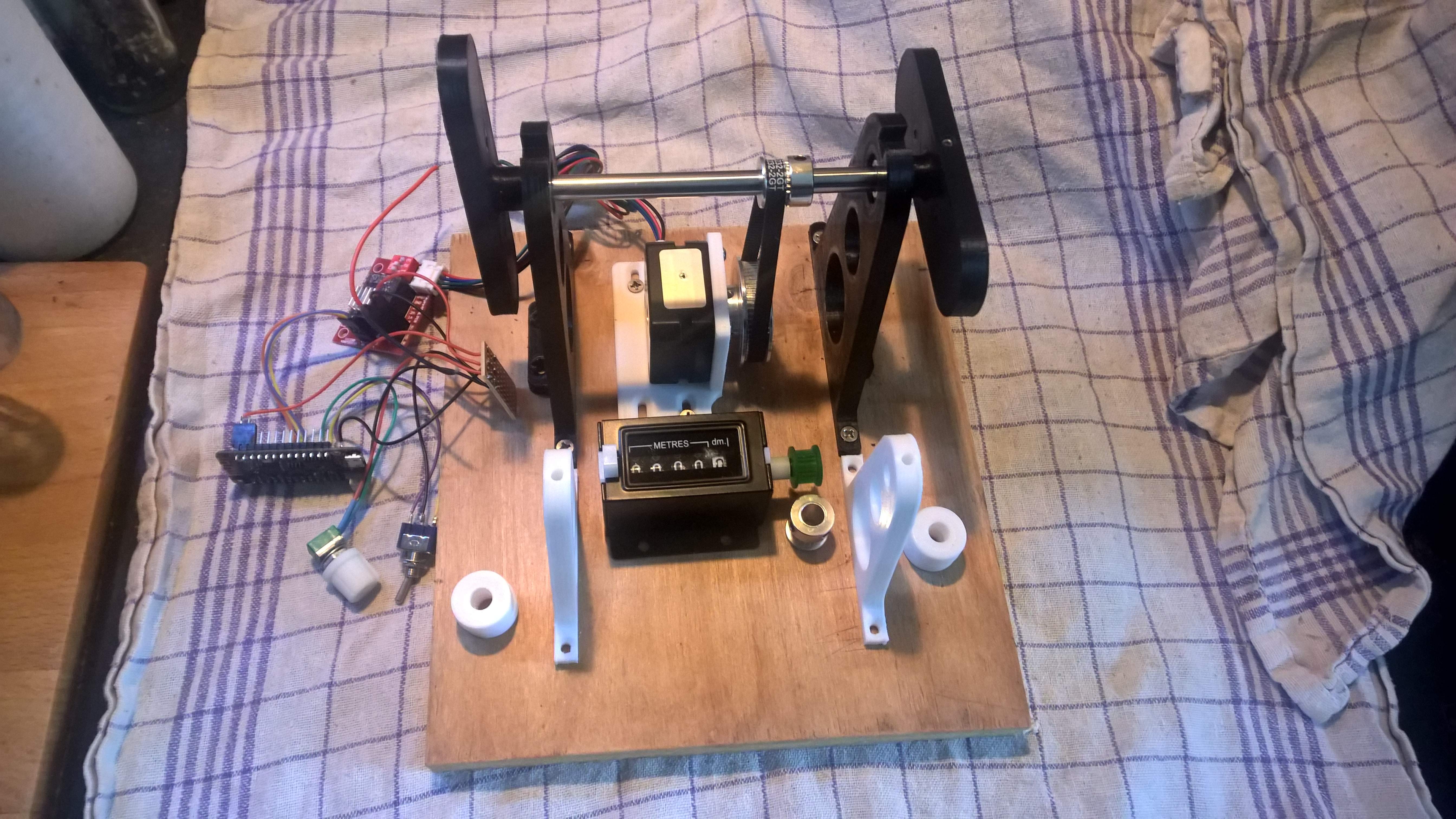
The winder uses a NEMA 17 stepper and DRV8825 driver, ESP32 for the controller. The stepper drives the main shaft via a 1:3 pulley set (60t and 20t) and GT2 closed-loop belt, aiming for around 1000rpm at the main shaft. I'm using a mechanical counter, driven 1:1 from the main shaft, mainly cos it counts forward and back and to do that with an optical or magnetic sensor requires a bit more thought. It also occurred to me that if the controller wigged out and reset during winding I'd lose the count.
I 3d-printed most of the other bits, designed in Fusion 360 (free for non-commercial use, and really easy to use).
I chose an ESP32 mcu cos it clocks at 80MHz whereas an Uno or Nano clocks at 16MHz which is pushing it for the code I'm running. Plus, it's really easy to vary the pulse frequency (and thus the motor speed) with an ESP32. There's also the possibility for remote monitoring via wifi.
I intend using a second stepper to control the distribution, but want to get it running manually first. Two things holding me back atm, code and tensioner...
Success! Thanks guys! Rounding over the edge of the spool has done the trick. I've wound my first coil. There are too many winds near the edges and the turns could be fractionally closer together, but I have a pickup winder.
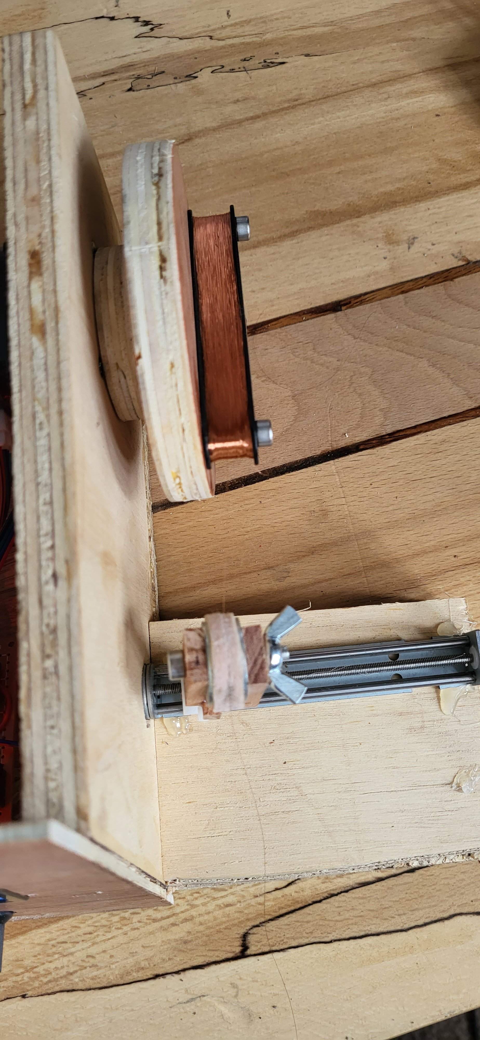
Nice!!!Success! Thanks guys! Rounding over the edge of the spool has done the trick. I've wound my first coil. There are too many winds near the edges and the turns could be fractionally closer together, but I have a pickup winder.
View attachment 4820522

Have you read the whole thread ?I intend using a second stepper to control the distribution, but want to get it running manually first. Two things holding me back atm, code and tensioner...
It's a long but interesting read and there is a lot of info in here.
I will, definitely. Thanks for the tip.Have you read the whole thread ?
It's a long but interesting read and there is a lot of info in here.
I've made my first pickup and it does pickup, but it hums. Not good for an active humbucker.
I have 2 coils, one wound clockwise and the other anticlockwise. I have connected the two starts together, one end to ground and the other to the +ve input. My circuit is designed to take one coil to each input as an alternative. 9V gets to the right places. The junction of R4 and R5 is 4.5V. The pickup coils show resistance in the right places. Touch the pole pieces, or any of the inputs and it hums louder.
Those of you who have done this before, do you have any ideas why it might humming so much? What might I have done wrong?
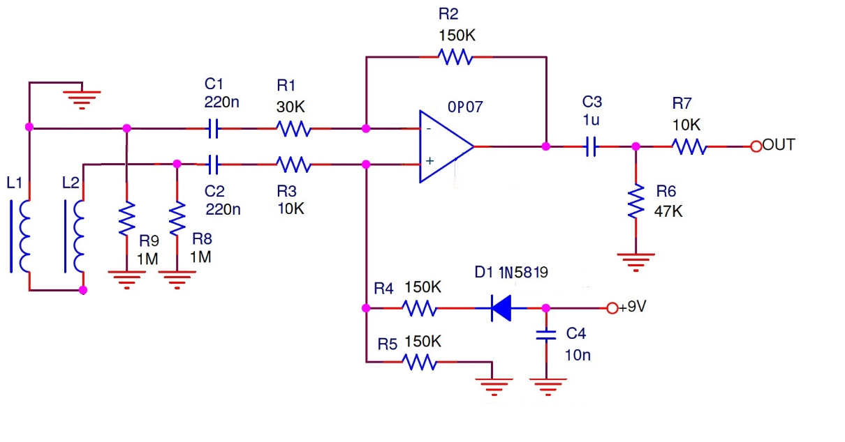
I have 2 coils, one wound clockwise and the other anticlockwise. I have connected the two starts together, one end to ground and the other to the +ve input. My circuit is designed to take one coil to each input as an alternative. 9V gets to the right places. The junction of R4 and R5 is 4.5V. The pickup coils show resistance in the right places. Touch the pole pieces, or any of the inputs and it hums louder.
Those of you who have done this before, do you have any ideas why it might humming so much? What might I have done wrong?
First thought - did you get the magnets in right way up? North on one bobbin, south on the other?I've made my first pickup and it does pickup, but it hums. Not good for an active humbucker.
I have 2 coils, one wound clockwise and the other anticlockwise. I have connected the two starts together, one end to ground and the other to the +ve input. My circuit is designed to take one coil to each input as an alternative. 9V gets to the right places. The junction of R4 and R5 is 4.5V. The pickup coils show resistance in the right places. Touch the pole pieces, or any of the inputs and it hums louder.
Those of you who have done this before, do you have any ideas why it might humming so much? What might I have done wrong?
View attachment 4821020
Second thought - try each coil on its own without the preamp, see if you get less hum, see if both have same output...
Not sure what C1 and R1 are doing, can you explain please?
Last edited:
Good ideas. It is easy enough to test the coils as a passive pickup, and to swap them to the non-inverting input and test that.
These diagrams might help explain the circuit. First, it is designed to work as a differential amplifier if required.
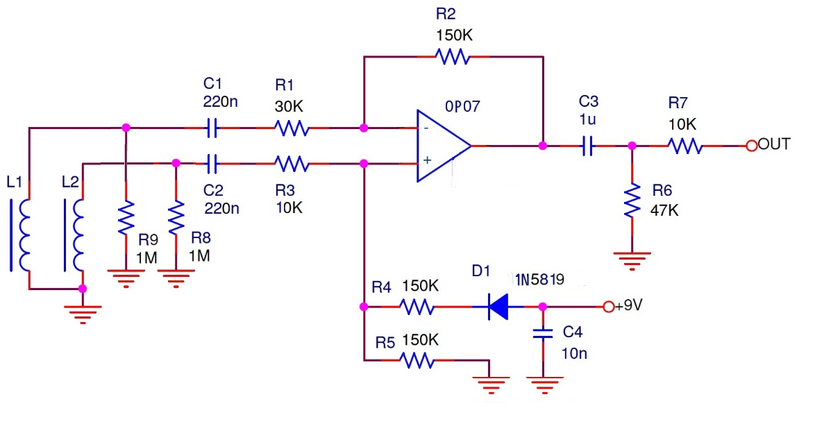
Second, it can be used as a single ended amplifier. Arranged like this, it probably makes more sense than the original drawing.
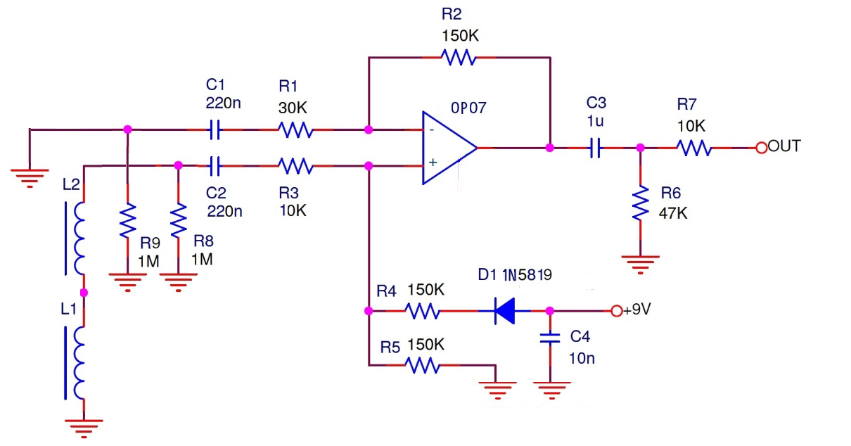
In single ended mode, R1 and C1 are redundant.
R8 and R9 are coil loading resistors. Once it's working, I'll play with the values of these to alter the way the coils sound. In theory, you can move the resonant peak to make it sound like different pickups.
These diagrams might help explain the circuit. First, it is designed to work as a differential amplifier if required.
Second, it can be used as a single ended amplifier. Arranged like this, it probably makes more sense than the original drawing.
In single ended mode, R1 and C1 are redundant.
R8 and R9 are coil loading resistors. Once it's working, I'll play with the values of these to alter the way the coils sound. In theory, you can move the resonant peak to make it sound like different pickups.
I've made my first pickup and it does pickup, but it hums. Not good for an active humbucker.
I have 2 coils, one wound clockwise and the other anticlockwise. I have connected the two starts together, one end to ground and the other to the +ve input. My circuit is designed to take one coil to each input as an alternative. 9V gets to the right places. The junction of R4 and R5 is 4.5V. The pickup coils show resistance in the right places. Touch the pole pieces, or any of the inputs and it hums louder.
Those of you who have done this before, do you have any ideas why it might humming so much? What might I have done wrong?
View attachment 4821020
For humbucking you need RWRP. The "P" refers to the polarity of the magnets, but you didn't mention those. Do you have them reversed?
The "W" refers to the wind, which technically can either mean the actual wind direction OR connection direction. However, from your description it sounds like you did both. In this case two hum cancelling "rights" may have made a "wrong". If you reverse the direction of the winds then you should have them wired start to finish.
If you are sure about your magnet polarity then try putting the start of one to the finish of the other and see if the hum goes away.
Good luck!
I said pole pieces before but that's not true. This is a rail pickup. I have a single magnet beneath the two coils and a two rails that go upwards through the coils, one from each end of the magnet. I stuck a piece of paper to the finish end of each coil before I cut the wire from the spool, so I'd remember which one was wound clockwise. I'm fairly sure that I've connected the two starts together but they're easily swapped.
I don't see the point of the differential configuration, unless you're amplifying the sum of the two pickups, not the difference. If you amplify the difference between the two coils, wouldn't you be amplifying the hum?Good ideas. It is easy enough to test the coils as a passive pickup, and to swap them to the non-inverting input and test that.
These diagrams might help explain the circuit. First, it is designed to work as a differential amplifier if required.
View attachment 4821027
Second, it can be used as a single ended amplifier. Arranged like this, it probably makes more sense than the original drawing.
View attachment 4821026
In single ended mode, R1 and C1 are redundant.
R8 and R9 are coil loading resistors. Once it's working, I'll play with the values of these to alter the way the coils sound. In theory, you can move the resonant peak to make it sound like different pickups.

technically can either mean the actual wind direction OR connection direction. However, from your description it sounds like you did both. In this case two hum cancelling "rights" may have made a "wrong". If you reverse the direction of the winds then you should have them wired start to finish.
@smart51 -
What he said.
That's how EMG do it. The magnet is north up on one coil and south up on the other so the signal is inverted. There's more on it here ElectroSmash - EMG81 Pickup Analysis.I don't see the point of the differential configuration, unless you're amplifying the sum of the two pickups, not the difference. If you amplify the difference between the two coils, wouldn't you be amplifying the hum?
Yeah, OK, that sounds like it. No. 1 son is in bed now, so I'll try this tomorrow. This is the simplest possible error, which is nice.@smart51 -
What he said.
Thanks, interesting info. I'm building an emg-style bass pickup atm, have several preamp designs I'm considering (like the classic Stingray 3-tone), I'll add this to the list of candidates.That's how EMG do it. The magnet is north up on one coil and south up on the other so the signal is inverted. There's more on it here ElectroSmash - EMG81 Pickup Analysis.


