• TalkBass has been independent since 1998. Add your voice.
    Create a free account to reply to discussions, view embedded media, and browse with fewer display ads.
    Join freeLog in
    Want zero display ads or expanded classifieds tools? Compare plans.

NAD Ampeg V-4B (project)

Which questions, after staring at the schematic, I don't see any difference in the channels.

IMHO it really doesn't have two full channels. Rather, it has two front ends with Gain controls. The voicing filters are linked, so they will be set the same on both front ends. The two signal paths are mixed together before the tone controls. If the two inputs don't sound the same it's probably due to differences in the tubes, damaged circuits, or component drift.

Why two front ends. This allow you to plug in two sources and adjust the gain for each source. Running two sound sources to an amp was not an unusual practice when the V4B was designed. You could run bass in one side and guitar or a mic in the other.

Amps like the Ampeg SVT and Fender Twin Reverb have two full channels that are not exactly the same. Because of the way the input jacks are configured, you can actually run two sound sources on each channel. I wouldn't call it a four channel amp though.
 
  • Like
Reactions: 6thplanet
Each channel has component tolerances which can make for sonic differences. Some PA amps have much the same topology, channel front ends are mixed together. In this case there are two.

A lot of stress can be put on the pots. Put the pot terminals into the PCB, tack if necessary, once the pot is tightened onto the front panel, then solder.

No reason to connect the input channels. I don’t see a sonic advantage. Besides, you have to be careful with the input signal pathway. Routing it there could add noise. The input is sensitive, use a shielded cable, grounded at one end only, at the jack. The shield should extend as close as possible to the resistor without touching the lead. A grid stopper (around 34K-47K works well) resistor should be as close as possible to the tube input. A grid stopper mounted at the jack is not as good. The purpose is to reduce RF noise into the preamp.

97D05ECC-25F4-4F71-AFF2-7B9A3B3D1AE4.jpeg
 
  • Like
Reactions: 6thplanet
That's exactly how I installed the potentiometer.

Read up on how and why's of grid stopper resistors, thanks! So yeah, this amp doesn't have them on the pre, but does on the power. (R37,38,41,42). Seems easy enough to add, I can cut the short trace that connects the wire to the tube socket pin and insert said resistor.
 
That's exactly how I installed the potentiometer.

Read up on how and why's of grid stopper resistors, thanks! So yeah, this amp doesn't have them on the pre, but does on the power. (R37,38,41,42). Seems easy enough to add, I can cut the short trace that connects the wire to the tube socket pin and insert said resistor.

Don't cut the trace! You need the 5.6M resistor in there as well. Solder the resistor to the pin-7 socket terminal or close to it. Even where the shielded wire attaches to normally is fine, the copper trace is not that long. It will be better than no grid stopper at all.
 

Attachments

The parallel resistor is on the input jack. The trace is the perfect length to add the grid resistor. I can solder one side directly to the pin and the other through the through hole that the input wire is inserted.
 
Got the caps installed. Played for about an hour and a half, never went below -64V. Seems fine now. Also seems a bit noisier than before. Kinda crackly noise floor? Kinda pecked around the pcbs, nothing really changed it. I did remove the ground polarity switch and cap. IDK, sounds good while playing, mid control works now, too.
 
  • Like
Reactions: Wasnex
Got the caps installed. Played for about an hour and a half, never went below -64V. Seems fine now. Also seems a bit noisier than before. Kinda crackly noise floor? Kinda pecked around the pcbs, nothing really changed it. I did remove the ground polarity switch and cap. IDK, sounds good while playing, mid control works now, too.

Could be a bad solder joint, a loose tube socket contact, a capacitor leaking DC, a bad tube or component….

A signal tracer can help identify where the noise is originating.

See the bottom of the page: Amp Tools
Also look for listening device or amplifier stethoscope.
 
  • Like
Reactions: Roxbororob
I removed the tubes, all the sockets seem tight. I gave a gentle tweak to all the terminals and reseated the tubes.

Added the grid stopper resistors that @beans-on-toast suggested. I had some 47K's on hand, so that's what went in there. All the tube socket solder joints weren't looking all that great, so I reflowed all those.
4DA126B5-AC23-4C9F-A463-320BC65B8A58.jpeg


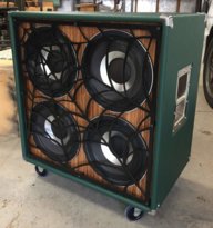
Next I added a switch in the polarity hole to combine the channels. It's nice to very between the two, just adds a bit more flexibility. The different tubes I have in those respective positions do have a bit of a tone difference. I have a dummy plug to unshort the one jack. I'm kinda thinking I might ditch the channel 2 jack and put a switch there.

I've been monitoring the bias voltage. In stand by it's at -64V, playing at practice volume it stays at -68V. So far so good. ...and good it does sound. The pairing of it with the JBL is totally old school cool.:cool: