- Feb 16, 2008
- 21,240
- 23,638
- Disclosures
- John K Custom Basses

TalkBass has been independent since 1998. Add your voice.
Create a free account to reply to discussions, view embedded media, and browse with fewer display ads.
Join free Log in
Want zero display ads or expanded classifieds tools? Compare plans.

... considering it needs several long-lead jumpers. ...

That does remind me - the current PCB layout is rather unsightly, considering it needs several long-lead jumpers. Has anyone tried to optimize the layout so more is routed using regular paths on the PCB? And yes, I'm fully aware of the "if it ain't broke" adage.

They aren't jumpers, it's just that the wires don't exit at the edge of the board.
I may changed the board around at some point because I want to add a gain trimmer.
The way the holes are set up is a low budget - but effective - way of providing a little extra strain relief. Mr Leo Fender's engineering pragmatism strikes again ...
The current layout is just a cleaned-up version of the original PCB. It wouldn't be hard to rework the layout and make it smaller and tighter - my best guess is that it could go down to 2/3 the current size without moving to SMT parts.

I want to give a small report. I installed one of these in my '87 Ibanez with my Neo Jazzbuckers and did a gig last night. My previous tests had been at my shop.
With the 220k resistor, the gain is pretty hot from the preamp. So if you have high output pickups, you might want to stick with the 100k. I might switch mine back. It works fine, no distortion or anything, but is a lot louder than my passive basses.
IIRC, I settled on 180K for my build, in which I used an LT 1351 opamp. Sounds really great in my old Travis Bean fretless.
That's a good idea. I'm thinking of using a trim pot.
I just did a custom control plate for someone that had a stacked volume and passive tone control, a blend and a stacked bass/treble control. It also had a bypass and a passive tone bypass: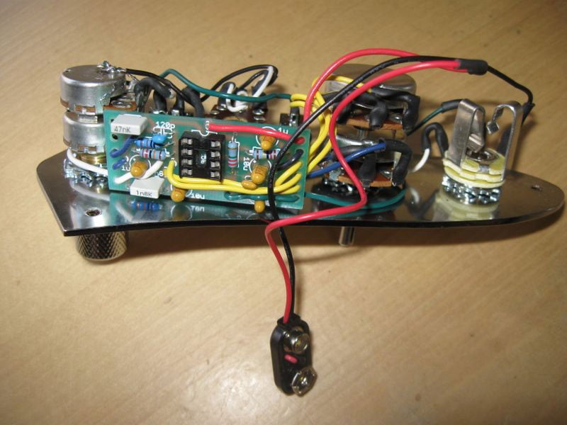
So how exactly were the controls interacting with the pre-amp? Did you set it-up with fixed values instead of pots?
Reason I ask is I'd like to use stacked tone pots but the dissimilar bass & treble control values (& reverse taper) didn't look doable unless you started rebuilding pots.


my best guess is that it could go down to 2/3 the current size without moving to SMT parts.

I could whip up an SMD board if anyone was interested. It would be tough to get it that much smaller, though - those 10uF electrolytics in the signal path don't get any smaller.
I wouldn't use tantalums in the audio path (or anywhere, really). The absolute best 10uf caps are the Nichicon MUSE series, which only come in through-hole.

I went with the Duncan 3-band and am very happy with it.
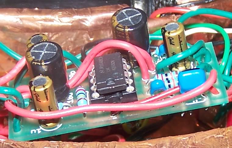
That's actually what I used in my most recent build. That and 1uF Fine Gold caps. I don't know how much those caps affect the tone, but the end products really sounds great.
Here's a picture of my most recent build. It's currently in my G&L L2500 Tribute bass.