ok that makes sense to me, all i need to know now is which one is the input capacitor, and what would be a good value capacitor to get.Yes, that is what he means. The idea here, if I'm understanding correctly, is to change the input capacitor to a larger value, which would mean desoldering the old leads and soldering the new capacitor in its place. However, I'm going to warn you the many modern chips are VERY sensitive to heat, so there's a chance of damaging you effect here.
Hope this helps.

Enjoy the benefits of a premium membership!
Upgrade Account
-
TalkBass has been independent since 1998. Add your voice.
Create a free account to reply to discussions, view embedded media, and browse with fewer display ads.
Join free Log in
Want zero display ads or expanded classifieds tools? Compare plans.
You are using an out of date browser. It may not display this or other websites correctly.
You should upgrade or use an alternative browser.
You should upgrade or use an alternative browser.
The Effect Builders Club!
- Thread starter B.C.
- Start date
More options
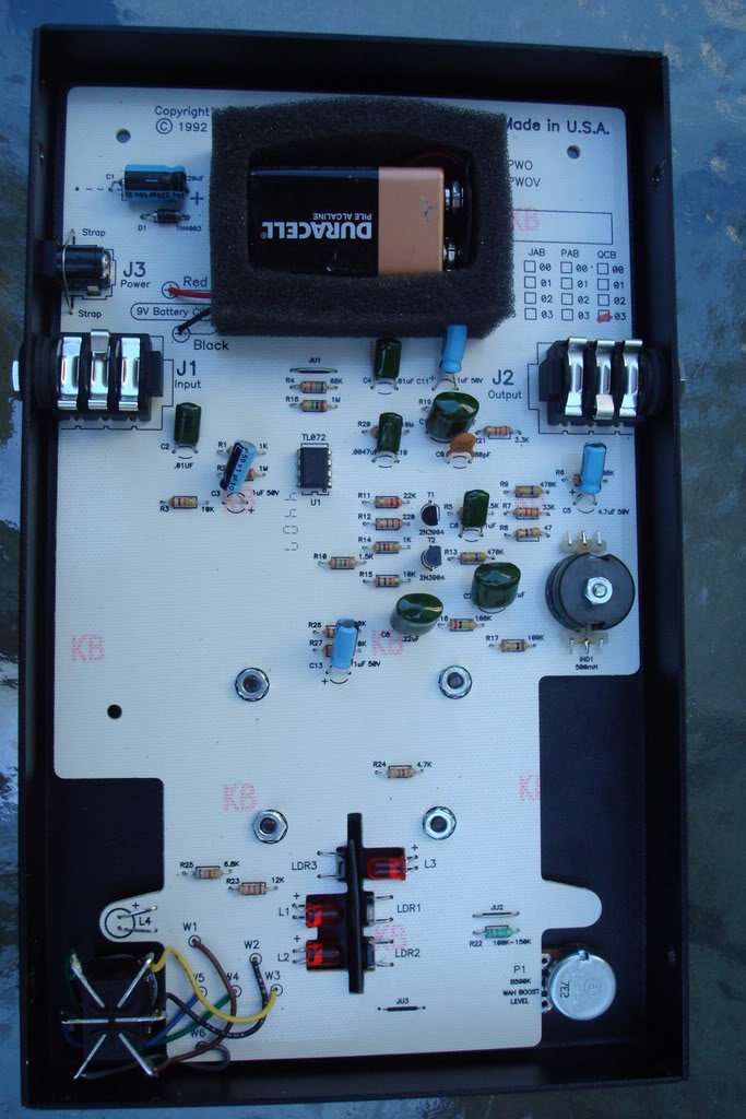
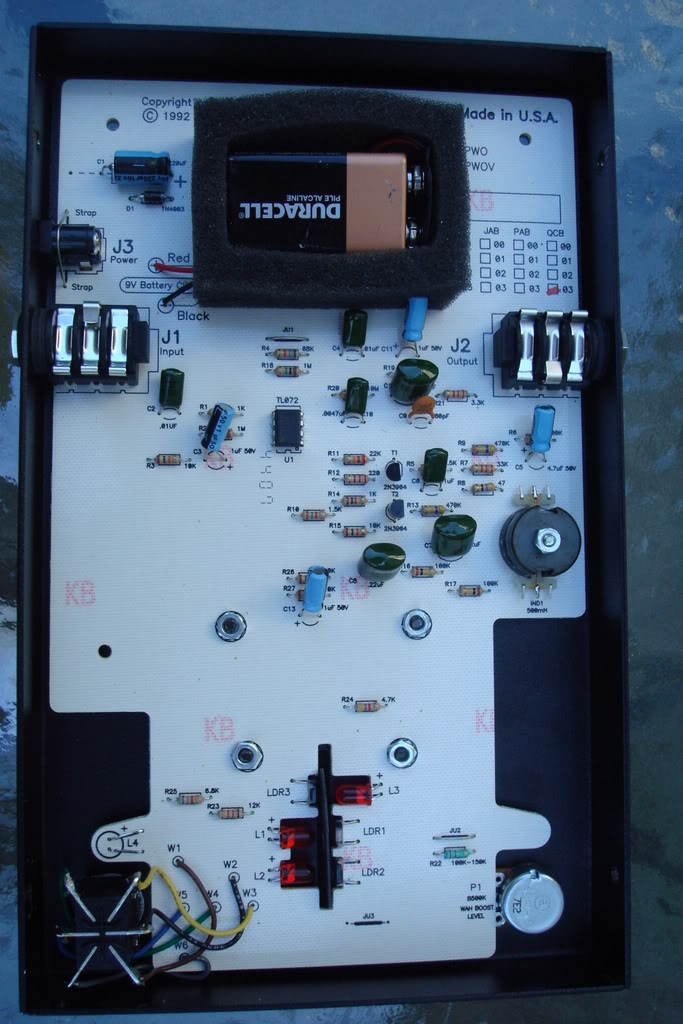
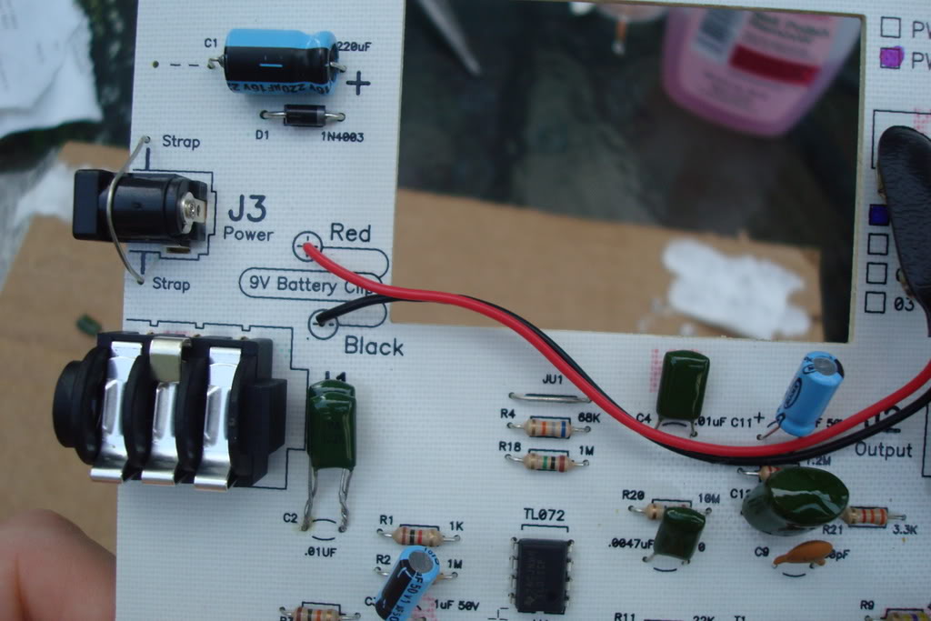
Who Replied?Maybe this will help me illustrate what im asking. Here is my Morley Power Wah Volume Pedal, with the back removed.
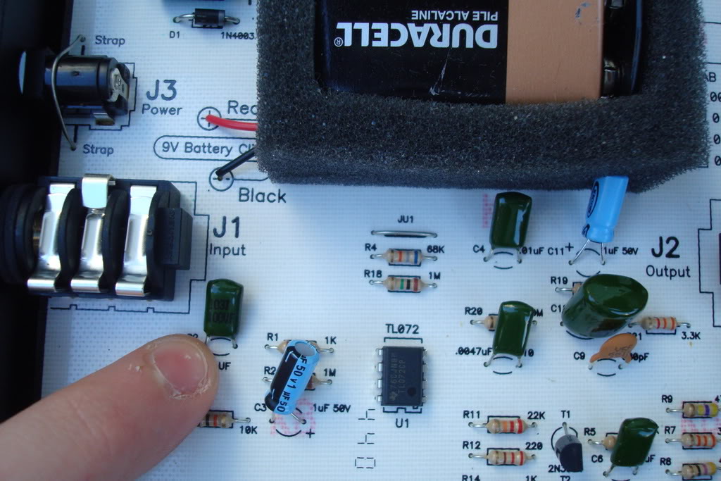
Here im pointing at the Capacitor (i assume thats a capacitor?) next to the jack marked input, is this the input capacitor you were refering to?
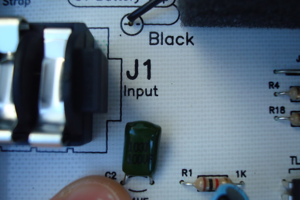
Here im pointing at the Capacitor (i assume thats a capacitor?) next to the jack marked input, is this the input capacitor you were refering to?

mikeboth
The last thing you'll ever see
Just get another cap of the same value and solder it in parallel with the existing one. Caps in parallel sum in value, so you will get twice the original value, and extend response by one octave (I think - bit rusty on this stuff). 
ok, so i would just solder a capacitor in parrallel in that one spot and it would improve repsonse to bass? god, i just took physics and already i cant remember any of this!Just get another cap of the same value and solder it in parallel with the existing one. Caps in parallel sum in value, so you will get twice the original value, and extend response by one octave (I think - bit rusty on this stuff).
..Resistance = 1/R +1/R+ 1?R.... o this may sound like a dumb question, but how do i remove the circuit board from the pedal housing? its face down and it doesnt move, do you knw how i can get it off?
Maybe this will help me illustrate what im asking. Here is my Morley Power Wah Volume Pedal, with the back removed.
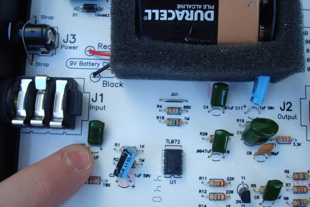
Here im pointing at the Capacitor (i assume thats a capacitor?) next to the jack marked input, is this the input capacitor you were refering to?
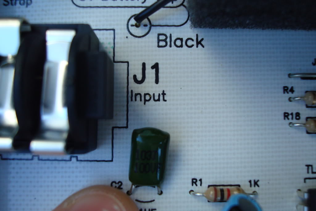
Yeah, it appears that way, wish I could see the trace though.
Wiring in parallel is certainly doable, but I would almost want to replace the cap for stabilities sake.
mikeboth
The last thing you'll ever see
ok, so i would just solder a capacitor in parrallel in that one spot and it would improve repsonse to bass? god, i just took physics and already i cant remember any of this!
..Resistance = 1/R +1/R+ 1?R.... o this may sound like a dumb question, but how do i remove the circuit board from the pedal housing? its face down and it doesnt move, do you knw how i can get it off?
Invalid Link Removed
... looks like the schematic. However, looking at it, the filter network that C1 is part of is unfamiliar to me, so in this case doubling it will probably not help. In most pedals - other than yours :^) - there is a DC-blocking cap on the input.
There's nothing wrong with soldering caps in parallel from a 'stability' point of view, and if you are playing around it's then easy to restore the pedal to it's original condition.
Just keep on removing nuts screws etc until the board can be removed, remember where they all go!
ok, so do you think i should replace the capacitor and then solder another identical one in parrallel? as in buying 2 capacitors?Invalid Link Removed
... looks like the schematic. However, looking at it, the filter network that C1 is part of is unfamiliar to me, so in this case doubling it will probably not help. In most pedals - other than yours :^) - there is a DC-blocking cap on the input.
There's nothing wrong with soldering caps in parallel from a 'stability' point of view, and if you are playing around it's then easy to restore the pedal to it's original condition.
Just keep on removing nuts screws etc until the board can be removed, remember where they all go!
ok, so do you think i should replace the capacitor and then solder another identical one in parrallel? as in buying 2 capacitors?
What he is saying is to buy the value of the capactor that is on the board and solder another one onto it lead by lead.
Ie if the board one is a .0047 micro F then buy a .0047 Micro F and solder the second to the first.
oh ok i getcha.What he is saying is to buy the value of the capactor that is on the board and solder another one onto it lead by lead.
Ie if the board one is a .0047 micro F then buy a .0047 Micro F and solder the second to the first.
i completed the soldering, and put it all back together
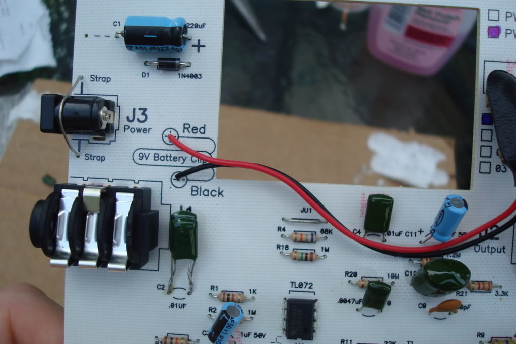
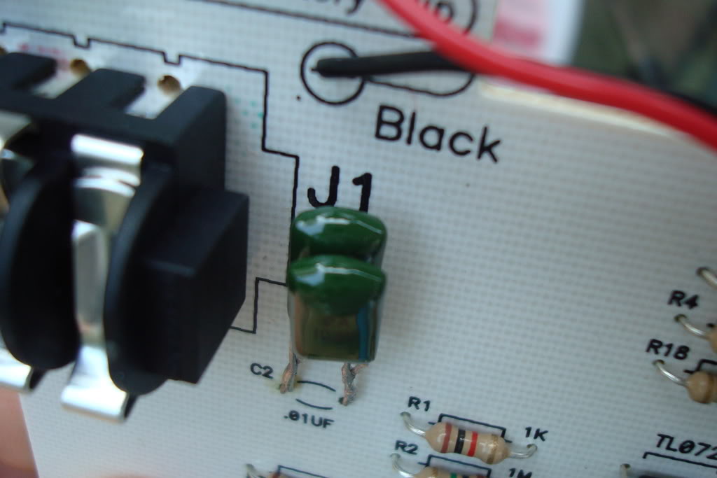
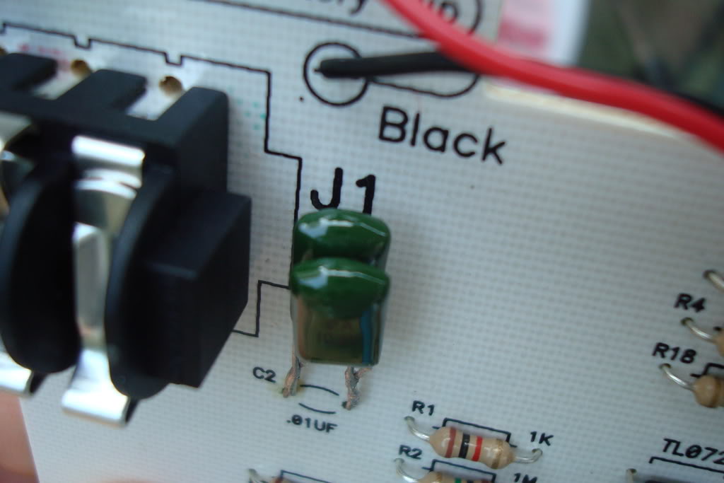
here you can see the two caps have been soldered together
i tried it out, and i can actually say it sounds better. i can see a huge improvement when its used with distortion. It handles the lows alot better, so im not getting as much of that crappy farting sound i should mod my effects more often! thanks to those who helped me out.
here you can see the two caps have been soldered together
i tried it out, and i can actually say it sounds better. i can see a huge improvement when its used with distortion. It handles the lows alot better, so im not getting as much of that crappy farting sound
i should mod my effects more often! thanks to those who helped me out.i completed the soldering, and put it all back together
here you can see the two caps have been soldered together
i tried it out, and i can actually say it sounds better. i can see a huge improvement when its used with distortion. It handles the lows alot better, so im not getting as much of that crappy farting sound
I'm glad you dig it my friend! Its really cool a forum can provide info like this.
yea, i did it with my big muff Pi too! this forum kicks so much assI'm glad you dig it my friend! Its really cool a forum can provide info like this.

yea, i did it with my big muff Pi too! this forum kicks so much ass
How do you like the Muff now?
mikeboth
The last thing you'll ever see
i completed the soldering, and put it all back together
Nice work, glad you got a good result.
its great, not quite as big a difference as with the wah, but its much more responsive and it doesnt get too farty sounding.How do you like the Muff now?
thanks, me too. feels nice to work on something yourself and be happy with the resultNice work, glad you got a good result.
You'd best ask the creator, but my feeling is that it's there to assist the implementation of the phase switch, and that removing it could upset things in regard to that switch. If you want to do without the switch then you could remove all of that and essentially duplicate the circuit of the "RED Return" section.Thanks a lot Niftydog....
BTW, on Splitter Blend there's a FET buffer before the switchable inverting/non inverting buffer on the green return part. Any idea why it's there ? Can I safely remove that FET buffer and get similar result ?

I think you've misunderstood what he's asking for. He wants to retain the oscillator section of the phaser but re-task the "phaser" section it to make it into a filter (ala wah pedal).I don't see why other people are saying this is so hard .... replace the circuitry that does the auto-sweeping with a pot...

I think you've misunderstood what he's asking for. He wants to retain the oscillator section of the phaser but re-task the "phaser" section it to make it into a filter (ala wah pedal).
Precisely! Only I'm not sure how to go about doing it. I have a general idea, but i'm not sure if it will actually pan out.
it's like this: LFO-> Varistor -> filter.
(i'm not on my computer, so i have no images).
is that feasable?
Precisely! Only I'm not sure how to go about doing it. I have a general idea, but i'm not sure if it will actually pan out.
it's like this: LFO-> Varistor -> filter.
(i'm not on my computer, so i have no images).
is that feasable?
Well, the way the MXR Phase 90 works is much like this, except there is no filter section per say, and you used a JFet(or MOSFET) to act as a variable resistor(according to Nifty Dog the varistor is not going to do what we want, thanks Nifty!!) I'm not quite sure a filter after the out of phase section is going to be much like the autowah. However, I've never done this so it could work. Let us know!
It's certainly feasible, but IMO not practical, simple or an efficient use of your time... unless you are an electronics geek desperate to learn.is that feasable?
You shouldn't need anything fancy like a Varistor, but you're on the right track. I'm sure with some searching at places like diystompboxes.com you'd find schems for LFO's (low frequency oscillators) and voltage controlled filters that you could mash together. (A wah is just a bandpass filter, BTW.)
If you were me, you'd just go and buy one and mod it for bass if necessary.


