Based on the Advanced Power Switching and Polarity Protection for Effects
article, this might be the simplest, heat shrinked and labeled appropriately.
Pretty slick!

TalkBass has been independent since 1998. Add your voice.
Create a free account to reply to discussions, view embedded media, and browse with fewer display ads.
Join free Log in
Want zero display ads or expanded classifieds tools? Compare plans.
Based on the Advanced Power Switching and Polarity Protection for Effects
article, this might be the simplest, heat shrinked and labeled appropriately.

I have a Passinwind question that is sort of off on a tangent but I am curious.
I was recently poking around my files and happened on a manual for a Yamaha NE-1 equalizer. Now I remember the hype about this which was that at the time it was supposed to be a "secret weapon" to produce hit records. Be that as it may, what I noticed is that the NE-1 is the opposite of this preamp. Namely that instead of a resonant peak there is a resonant dip. So my pondering is to wonder if there is some kind of modification to this circuit that could be done where a toggle switch might change it from a peak to a dip in response thus giving a possibility of both options. I wouldn't be surprised if it were too complex to be practical, but nevertheless I was just wondering.


Built the Super Tone Control over thirty years ago. It was a pretty cool tone circuit... very flexible!I'll take a look at the possibilities, but I have a feeling it won't be that easy, given the relatively simple LPF format I went with. However, my initial design for the LPF preamp used a state variable filter, which can easily do both. Take a look at Craig Anderton's Super Tone Control for a well known and DIY friendly example of that.
There's a version that switches the NE-1 into a LPF. Since the NE-1 is a simple design it would be easy to incorporate it. switching pop noise might be an issue.
Built the Super Tone Control over thirty years ago. It was a pretty cool tone circuit... very flexible!
Yep, I built one a zillion years ago when Craig's book was brand new.
Yep, I built one a zillion years ago when Craig's book was brand new.

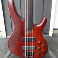
Still waiting on the op amps for my project, but looked at starting to wire up the pots. To my dismay the pots from the parts list are 3/8" but the holes on the bass are 6mm. I don't really want to drill the holes out so am looking at replacements, but for the 5k which is the frequency pot I'm only finding 50mW power rating. I haven't done any circuit analysis since navy school back in '89, so I'm not sure but that seems a little tight.

Also:These are SMD parts, but hand soldering to an adapter board is definitely workable. Some people are asking pretty stupid money for the adapter boards, but there are plenty of design shares at OSHpark; figure about a buck for three, shipping included.

Clever!
Curious to hear how that goes!... So I'll be testing opamps head to head more thoroughly in the next few days.
I'm getting a fair amount of low end roll off with C2 1uF in there:
View attachment 2885710
Simulation is showing that a 4.7uf will get me to 40Hz before it starts rolling off. @Passinwind is there anything I've missed regarding this value? Also, I'm assuming the Excel BOM has the current correct values and not the schematic linked from the first post, right?
It's been a lot longer than I figured on, but here's a measurement I took today of one of my NAMM boxes, Bass and Mids set flat, Res at minimum, Freq at max.:
View attachment 3015156
...which jibes pretty well with my Spice models. So if you never resolved this I will be happy to try to figure out what's up.