
Enjoy the benefits of a premium membership!
Upgrade Account
-
TalkBass has been independent since 1998. Add your voice.
Create a free account to reply to discussions, view embedded media, and browse with fewer display ads.
Join free Log in
Want zero display ads or expanded classifieds tools? Compare plans.
You are using an out of date browser. It may not display this or other websites correctly.
You should upgrade or use an alternative browser.
You should upgrade or use an alternative browser.
The "Quiet Mesa Walkabout" project...
- Thread starter Vic
- Start date
More options
Who Replied?

kevmoga said:Me too. I even have the same Silenx fan ready to go. Only hitch is that as far as I can tell from a brief look, the WA has a red wire and a black wire soldered to the stock fan. The Silenx has 3 wires going into a plug type thing - all three wires look just alike, i.e. no red/black. Any suggestions for installation appreciated.
My guess is the third wire is a fan casing ground wire. Often fans are electrically isolated from the chassis they are mounted in to reduce fan caused vibrations.
I believe these are 12v dc fans? If that is the case you can use a 9 v battery to determine which 2 wires will work. Simply cut the connector off, strip some insulation back on all three wires and touch two wires to the 9V intermittently and observe fan movement. Note which wire you are using on the + side of the battery and the - and the proper direction of the fans rotation. Use a pen or marker on the two wires that get the fan moving the right direction and connect the + to the WA red wire and the - to the WA black. You can either cut the spare wire off completely or tape up the end of the wire.

Chef
In Memoriam

The third wire is usually for an RPM sensor, which is used by some computer motherboards. It's not needed for this project. Sometimes fans also have a "low speed" wire and a "high speed" wire.
Chef
In Memoriam

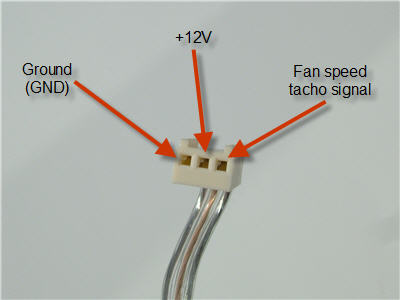
I just did a little googling, and the third wire on the Silenx is a "tacho" wire (RPM sensor) per the FAQ on their site. I also found this image, which shows the pinout of the connector. Enjoy.
Chef
In Memoriam
I don't recommend this unless it's impossible to find wiring diagrams, and these are such generic specs, that should never be a problem. It took me only a few minutes to find the image I just posted, which documents this standard pinout.I believe these are 12v dc fans? If that is the case you can use a 9 v battery to determine which 2 wires will work. Simply cut the connector off, strip some insulation back on all three wires and touch two wires to the 9V intermittently and observe fan movement. Note which wire you are using on the + side of the battery and the - and the proper direction of the fans rotation. Use a pen or marker on the two wires that get the fan moving the right direction and connect the + to the WA red wire and the - to the WA black. You can either cut the spare wire off completely or tape up the end of the wire.
The reason I don't recommend it is, I have no idea what might happen to the fan if you applied power between the tacho wire and something else. Maybe nothing, but you have to be willing to risk the cost of the fan to find out, and with the info so easy to find, it's not really necessary.


MikeBass
Supporting Member
- Nov 4, 2003
- 11,943
- 3,137
- Disclosures
- Endorsing artist- Suhr basses, PedalTrain, GHS, Ultimate Ears
The one who wins the wet t-shirt contest.Yeah, but which fan is best for metal?????
Chef
In Memoriam

Thanks for all the responses, I'm embarrassed to admit that it never occurred to me to explore the Silenx website  . I have to say that either I have a really loud fan or I'm just one of those people that is particularly bothered by the noise. Thanks again.
. I have to say that either I have a really loud fan or I'm just one of those people that is particularly bothered by the noise. Thanks again.
I don't recommend this unless it's impossible to find wiring diagrams, and these are such generic specs, that should never be a problem. It took me only a few minutes to find the image I just posted, which documents this standard pinout.
The reason I don't recommend it is, I have no idea what might happen to the fan if you applied power between the tacho wire and something else. Maybe nothing, but you have to be willing to risk the cost of the fan to find out, and with the info so easy to find, it's not really necessary.
Your absolutely right. My suggestions were general and as a last resort. The factory schematic makes much more sense. Having said that, I'd be surprised if a 9V battery would impart any harm to the tach sensor. Usually they are just a magnetic reed switch driven by a permanent magnet that rotates and gives a 12V pulse out.
Sound advise on your part though
This thread has me thinking.... I'm going to build an automatic thermal control for my stock fan. I plan on running it at 2 Ohms every now and then and would prefer to keep the maximum air flow through the amp. I have removed the back cover from my Scout and the added venting allows the full flow from the stock fan to take place.
Those of you with older style WA's without the new top chassis venting, will be fine with the quieter slightly lower flow replacements you have chosen as I think the venting on the old style WA's won't allow the full 36.5 CFM anyway.
I found this circuit on the Basic Car Audio Electronics website:
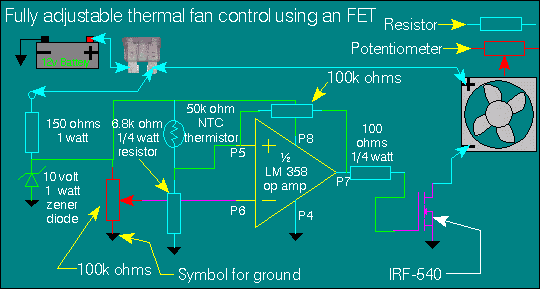
Looks interesting, as you can control the temp at which you would like the fan to come on with a pot adjustment. My Eden WT-400 Plus has a similar circuit and it's rather nice. I'd never hear my fan come on in a typical low volume practice but on gigs when the heat is on, the fan kicks in and chills everything out. Of course at that point you don't notice the fan at all because of the louder sound levels.
Because electronics are cheaper by the dozen, I would be willing to make some extras if some of you would like one too. Just let me know if there is any interest.
Those of you with older style WA's without the new top chassis venting, will be fine with the quieter slightly lower flow replacements you have chosen as I think the venting on the old style WA's won't allow the full 36.5 CFM anyway.
I found this circuit on the Basic Car Audio Electronics website:
Looks interesting, as you can control the temp at which you would like the fan to come on with a pot adjustment. My Eden WT-400 Plus has a similar circuit and it's rather nice. I'd never hear my fan come on in a typical low volume practice but on gigs when the heat is on, the fan kicks in and chills everything out. Of course at that point you don't notice the fan at all because of the louder sound levels.
Because electronics are cheaper by the dozen, I would be willing to make some extras if some of you would like one too. Just let me know if there is any interest.


Bump... I just picked up a used, older Walkabout, which suffers from Loud Fan Syndrome, so I checked out the SilenX links in this thread and they are all out of stock or discontinued. So, what are the current replacement options in all your's esteemed opinions?

It looks like Amazon has the Silenx IXP-54-14 fan:
http://www.amazon.com/SilenX-Ixtrema-Series-14dBA-32cfm/dp/B000PKF3YS
Can someone confirm that this one is the same as mentioned earlier in the thread?
http://www.amazon.com/SilenX-Ixtrema-Series-14dBA-32cfm/dp/B000PKF3YS
Can someone confirm that this one is the same as mentioned earlier in the thread?
As an Amazon Associate, TalkBass may receive commissions from qualifying purchases made via links on this site.

Anyone? Bueller? That fan says it has the best noise-to-airflow of any PC fan in the world and it's the right size, so it should work, right?
This might be a fun project for my Walkabout.
This might be a fun project for my Walkabout.

Vic, or anyone that's performed this swap...was your hot lead connected to a resistor and then globbed with RTV at the solder joint?
I always prefer to make direct connection but with silicon all over the joint I'm trying to think of another way of making the connection.
I always prefer to make direct connection but with silicon all over the joint I'm trying to think of another way of making the connection.


