

Enjoy the benefits of a premium membership!
Upgrade Account
-
TalkBass has been independent since 1998. Add your voice.
Create a free account to reply to discussions, view embedded media, and browse with fewer display ads.
Join free Log in
Want zero display ads or expanded classifieds tools? Compare plans.
You are using an out of date browser. It may not display this or other websites correctly.
You should upgrade or use an alternative browser.
You should upgrade or use an alternative browser.
There's another storm brewing!
- Thread starter pilotjones
- Start date
More options
Who Replied?
Yeah, no fruity beers for me either. I think they have a blackberry thats pretty off as well. Different strokes I guess.
Great build so far, even better than the first.
Great build so far, even better than the first.

The only fruity beer I like is Long Trail's Blackbeary Wheat. It's a subtle aftertaste, rather than a "let's beat you over the head with the fruit" thing.

Have any of you beer enthusiasts tried Mort Subite? Apparently their fruity offerings are quite good, or so I've been told by some of my friends.

Yeah, I was hoping for just a hint of fruit. I don't like fruity beers, that's why I didn't buy the Magic Hat. So far there's been only one blueberry beer I've liked, which had just a hint. But nothing so far had been as bad as this Sam Adams.
I have liked a couple of the tart citrus addition beers. One was Great South Bay blood orange, and two were with grapefruit. They made for a good cold-one-in-the hot-sun beer.
I have liked a couple of the tart citrus addition beers. One was Great South Bay blood orange, and two were with grapefruit. They made for a good cold-one-in-the hot-sun beer.

Wings!
Summary of the last few days:
Determined and marked the hole positions and their bits
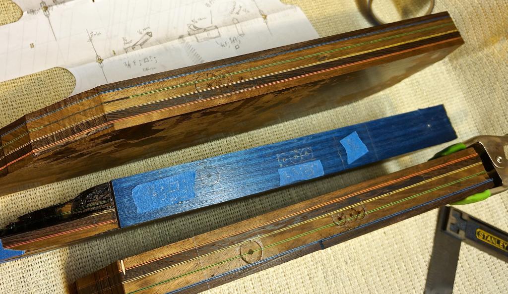
Decided to use 3/8" dowels for alignment. I want no slippage, and the alignment has to be right, otherwise the striped in the wings and in the beam won't match up.
Made a jig for drilling the alignment dowel holes
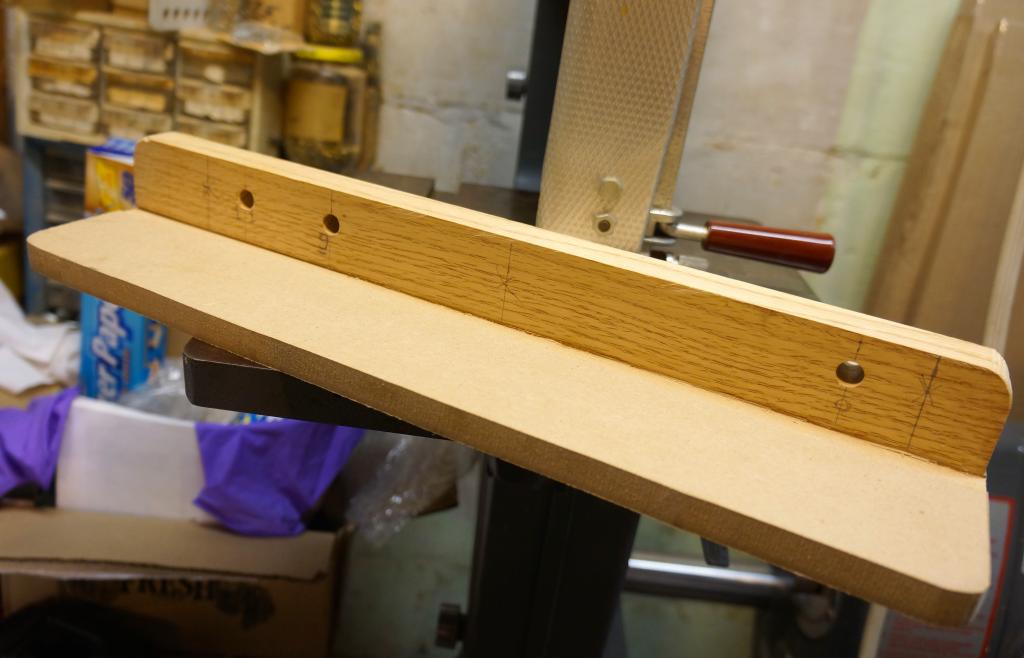
The jig is actually two-sided like an upside-down T. That way I can drill for one part, registered against the reference surface, then drill the mating part without flipping the jig around. By doing this, the same jig hole is used for the tail-end hole for both parts, so that even if the two holes in the jig vary in their height off the datum surface, there will still be no angle induced.
Drilling the alignment holes
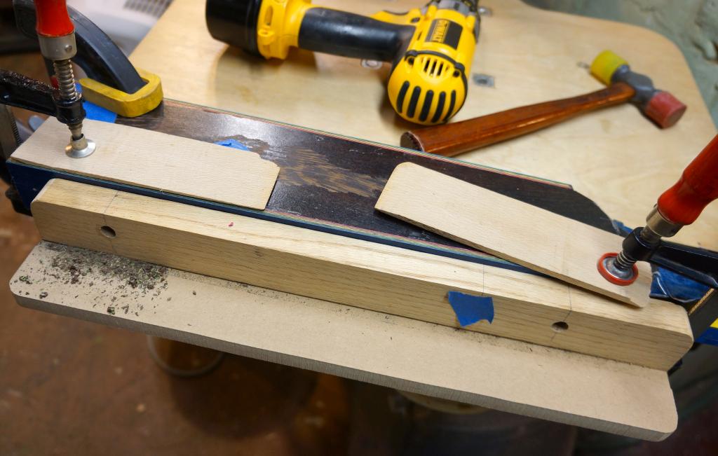
I did this with a handheld drill rather than the drill press, because my pillar was too short to drill the wings with a 3/8 bit chucked. Yes, the piece of blue tape is to cover up the third hole (for the other wing) so I don't drill out the wrong one.
Boring the holes
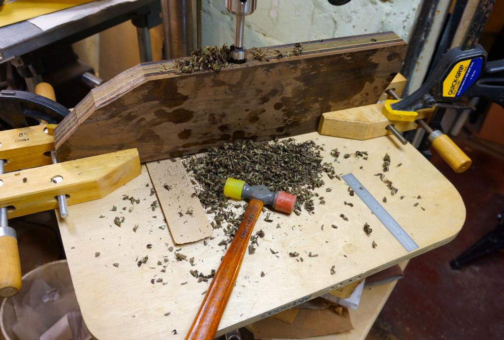
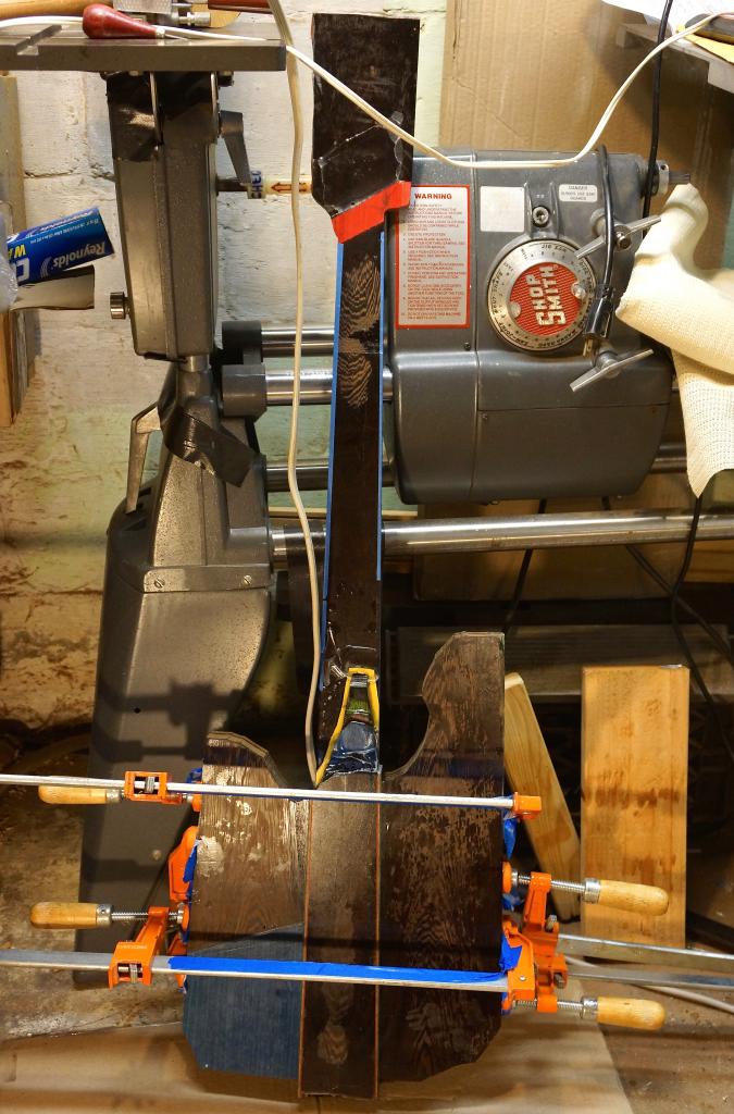
Forstners and twist drills. The parallel jaw clamps allowed me to raise up one end to make the top surface perpendicular to the spindle. There was also one oblique hole that I put in with a hand drill.
The three parts, all holes in
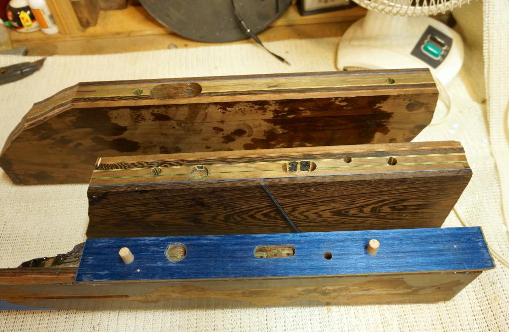
After this I re-leveled the mating surfaces. Then I lined the wiring channel voids with copper foil. If it works out, I'll just have to connect things up with another thin copper strip. If the later routing tears it up, nothing lost.
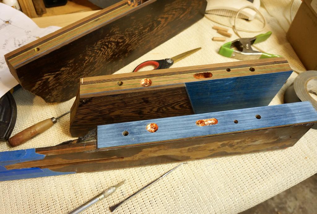
Then I cut out most of the scrap inside the horn areas with the bandsaw, and glued it up. That's where it's at now.
Summary of the last few days:
Determined and marked the hole positions and their bits
Decided to use 3/8" dowels for alignment. I want no slippage, and the alignment has to be right, otherwise the striped in the wings and in the beam won't match up.
Made a jig for drilling the alignment dowel holes
The jig is actually two-sided like an upside-down T. That way I can drill for one part, registered against the reference surface, then drill the mating part without flipping the jig around. By doing this, the same jig hole is used for the tail-end hole for both parts, so that even if the two holes in the jig vary in their height off the datum surface, there will still be no angle induced.
Drilling the alignment holes
I did this with a handheld drill rather than the drill press, because my pillar was too short to drill the wings with a 3/8 bit chucked. Yes, the piece of blue tape is to cover up the third hole (for the other wing) so I don't drill out the wrong one.
Boring the holes
Forstners and twist drills. The parallel jaw clamps allowed me to raise up one end to make the top surface perpendicular to the spindle. There was also one oblique hole that I put in with a hand drill.
The three parts, all holes in
After this I re-leveled the mating surfaces. Then I lined the wiring channel voids with copper foil. If it works out, I'll just have to connect things up with another thin copper strip. If the later routing tears it up, nothing lost.
Then I cut out most of the scrap inside the horn areas with the bandsaw, and glued it up. That's where it's at now.
Should have invested in a biscuit jointer, or found one to borrow. Regardless, looks good.
lowsound
lowsound
I had a biscuit joiner available to me. I understand that it can do a good job aligning in the direction across its thickness, since the cutter indexes that way. But the position in the other direction (along the joint) was crucial too, and the biscuits have extra space there, as I understand it, allowing slip along the joint.
Plus, I don't like the idea of putting in a piece of compressed wood in there that could decide to expand later.
Plus, I don't like the idea of putting in a piece of compressed wood in there that could decide to expand later.
New Template
As I mentioned before, the template for SK1 was out of proportion, and I wanted to correct that. Since with the corrected image for SK2, the body is about 1/2" longer, I also adjusted the cutaway at the treble side to go a little deeper, since I like the clear access on SK1. Printed it out, pasted it up,
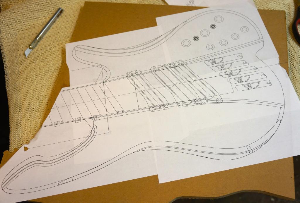
and cut out the template on the bandsaw, and then finished with edge & drum sander, and sandpaper on blocks.
It turns out that this one will also be about 1/8" - 1/4" narrower than SK1. I like the proportions of both, though. And the longer bass side horn should work well for balance.
Rough cut body
I did the band sawing. I traced the outline from the template, then decided the contrast of pencil on walnut wasn't enough to be safe, so I blue taped it and traced again.
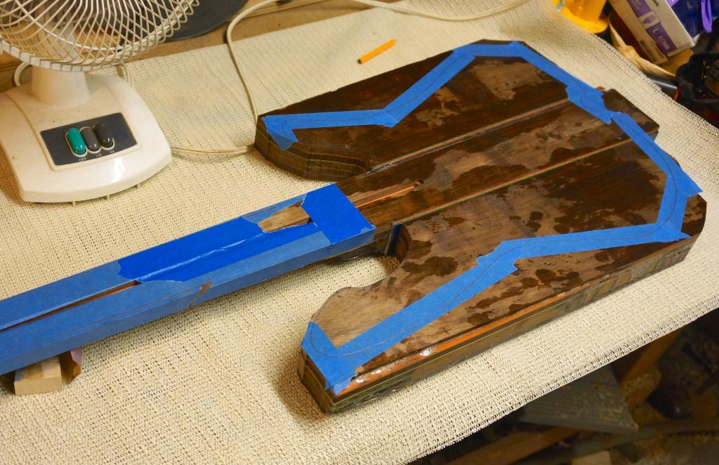
(I sort of like the that angular shape. Hmmm...)
Bandsawed it out, fairly close to the line. I left a tab at the tail because the index hole for the fretboard is there.
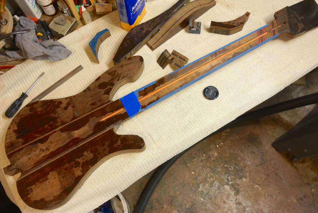
It looks like a bass now! It also handles much more like a bass now, instead of like a brick on a stick.
A nice preview of lamination madness, at the butt end.
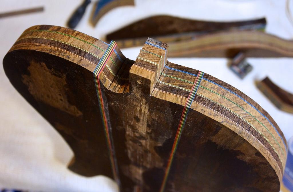
Everything lined up beautifully.
Bonus artsy fartsy perspective shot at the crotch of the treble cutaway, where I had to nibble it out with the bandsaw. Damned neck-thrus!

Might have been a little artier if I had bothered to set up a better backdrop.
As I mentioned before, the template for SK1 was out of proportion, and I wanted to correct that. Since with the corrected image for SK2, the body is about 1/2" longer, I also adjusted the cutaway at the treble side to go a little deeper, since I like the clear access on SK1. Printed it out, pasted it up,
and cut out the template on the bandsaw, and then finished with edge & drum sander, and sandpaper on blocks.
It turns out that this one will also be about 1/8" - 1/4" narrower than SK1. I like the proportions of both, though. And the longer bass side horn should work well for balance.
Rough cut body
I did the band sawing. I traced the outline from the template, then decided the contrast of pencil on walnut wasn't enough to be safe, so I blue taped it and traced again.
(I sort of like the that angular shape. Hmmm...)
Bandsawed it out, fairly close to the line. I left a tab at the tail because the index hole for the fretboard is there.
It looks like a bass now! It also handles much more like a bass now, instead of like a brick on a stick.
A nice preview of lamination madness, at the butt end.
Everything lined up beautifully.
Bonus artsy fartsy perspective shot at the crotch of the treble cutaway, where I had to nibble it out with the bandsaw. Damned neck-thrus!
Might have been a little artier if I had bothered to set up a better backdrop.
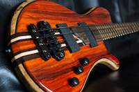



Those laminations are going to be something else by the time you get this thing carved.
Speaking of laminations... Am I seeing things, or is there a missing layer of wenge on the back of the treble wing? It sure as heck looks like it from the "lam-madness preview" picture...
Speaking of laminations... Am I seeing things, or is there a missing layer of wenge on the back of the treble wing? It sure as heck looks like it from the "lam-madness preview" picture...
Last edited:
Oh. Duh... Almost forgot that PJ does his cavity covers all the way to the edge. Carry on, gentlemen. *returns to lurk mode*

Those laminations are unparalleled! Or in this case, paralleled!

bassman314
I seem to be a verb, an evolutionary process...
Very nice!
Fantastic.
It's nice to see that the layers line up perfectly.
Those laminations are going to be something else by the time you get this thing carved.
Speaking of laminations... Am I seeing things, or is there a missing layer of wenge on the back of the treble wing? It sure as heck looks like it from the "lam-madness preview" picture...
^ Control cavity cover.
So beautiful. I'm really enjoying this build.
Those laminations are unparalleled! Or in this case, paralleled!
Thanks, all. I'm pretty happy with it right now!That bass is going the be stunning when you get it carved and finished.
I think I will be going with rounded surfaces rather than bevels, as nice as the bevels can look on some things like Matteo's current build. I think bevels require more of an overall, preconceived unifying plan to work, and I'm going to be feeling this out I go along. There may be some flat surfaces in thee somewhere. Maybe.
As to the question, yes, cavity cover is missing in the pics. Since I still have to laminate it (it will have hidden magnets), I haven't cut the perimeter on it yet, so I left it out of the pics.
Right now I'm doing more work on the cavity, so that I can make a cutting template for it. The break line between the cover and the rest of the body is about .350 lower towards the tail than I had intended, due to the misprinted template thing, so I will have a little less room there than I had expected. It actually affects my magnet placements on the lip more than the cavity itself.
I've modeled in the wiring holes that I put in for the pickup wires, and I think I've found a good place to mount the preamp LED. I was going to put a stainless clip to mount the 9v battery in there, but I think I will do a carved pocket instead, similar to SK1 but a little better.
I did some small adjustments to the knob positions, after measuring up their spacings. I also modeled in my DPDT for pickup selection, to be sure the fit is good versus the battery. I moved the jack further along the wall, away from the tail, to make it easier to stand up the bass without destroying an attached guitar cable. It now projects at an exactly 1 radian angle to the centerline.

I think I will be using an electronics industry solution for the electrical connection between the cavity and the cover. I've ordered a part to do it. But I was wondering--how do you people make the connection, when you have a cover that is flush-fitting at the surface? In this case, fully covering both the cover and the lip with copper (like I did on my first) won't work, because it would then show a copper line at the edges, caught between the blue-black-blue.
Last edited:


