Hello all,
I have come up with this:
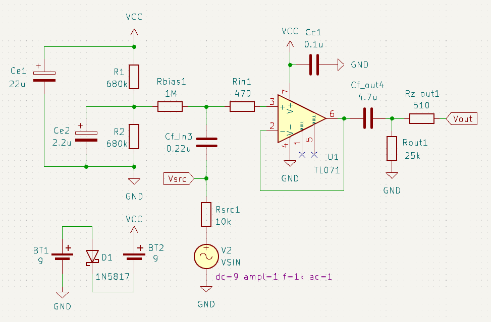
It is a 18V single supply (bottom left) dual magnetic pickup buffer, based on the TL072 op amp (one half of the chip shown here, for one pickup).
Pickup is modeled very simply at the bottom.
Since the buffer uses single supply, we need to generate a mid-supply bias voltage using a voltage divider (left). This voltage is used to bias the non inverting inputs of the TL072. I am injecting the bias voltage to the inputs using Rbias1 = 1MΩ.
The op amp is obviously in non inverting configuration and gain is unity, no amplification.
Since the op amp is working with the signal at a 9V bias level, input and output coupling capacitors are necessary, to remove the DC component from the previous (pickup) and next (potentiometer) stages. They are 0.22uF and 4.7uF respectively.
I also added Rin1 = 470Ω as a small input protection and Rz_out1 = 510Ω as some output protection.
The main question I have is what do I do after the op amp output. The output coupling 4.7uF cap is certainly a necessity. But the two resistors I have next is pure speculation on what would be best to lead this output into one of the wiper inputs of a 25KΩ, MN taper potentiometer. I mention the potentiometer specifically because the main intention behind building this buffer is a smooth blending experience across the whole tonal spectrum between the two pickups. Something like a home brewed active blend control a la EMG ABC.
What do you guys think would be best post the op amp output and into the blend pot? If you have other recommendations/comments about the circuit they are very welcome. I 'd like to start prototying this on a zero breadboard so I would like to have a better idea as to what I will need to wire up together before a start.
Many thanks!
I have come up with this:
It is a 18V single supply (bottom left) dual magnetic pickup buffer, based on the TL072 op amp (one half of the chip shown here, for one pickup).
Pickup is modeled very simply at the bottom.
Since the buffer uses single supply, we need to generate a mid-supply bias voltage using a voltage divider (left). This voltage is used to bias the non inverting inputs of the TL072. I am injecting the bias voltage to the inputs using Rbias1 = 1MΩ.
The op amp is obviously in non inverting configuration and gain is unity, no amplification.
Since the op amp is working with the signal at a 9V bias level, input and output coupling capacitors are necessary, to remove the DC component from the previous (pickup) and next (potentiometer) stages. They are 0.22uF and 4.7uF respectively.
I also added Rin1 = 470Ω as a small input protection and Rz_out1 = 510Ω as some output protection.
The main question I have is what do I do after the op amp output. The output coupling 4.7uF cap is certainly a necessity. But the two resistors I have next is pure speculation on what would be best to lead this output into one of the wiper inputs of a 25KΩ, MN taper potentiometer. I mention the potentiometer specifically because the main intention behind building this buffer is a smooth blending experience across the whole tonal spectrum between the two pickups. Something like a home brewed active blend control a la EMG ABC.
What do you guys think would be best post the op amp output and into the blend pot? If you have other recommendations/comments about the circuit they are very welcome. I 'd like to start prototying this on a zero breadboard so I would like to have a better idea as to what I will need to wire up together before a start.
Many thanks!