• TalkBass has been independent since 1998. Add your voice.
    Create a free account to reply to discussions, view embedded media, and browse with fewer display ads.
    Join freeLog in
    Want zero display ads or expanded classifieds tools? Compare plans.

Trim pot to even out volume difference between Series and Parallel/Single Coil

PraiseBassing

Supporting Member
Mar 6, 2017
2,494
4,512
California
I am hoping to get as much detailed information as possible to help me out. Please assume I know nothing and you have to explain everything fully.

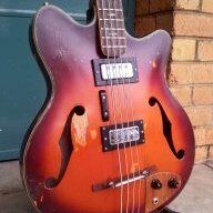
I am looking to swap out some pickups and install a pair of Delano SBC 5 Driver HE/S-4 pickups in my bass. I want to have a 3 way mini toggle to be able to switch between Series, Single Coil, and Parallel. My question stems from the switching. I want to even out the the volume differnce that is associated with this.

I feel that a small trim pot located in the control cavity will be easier for me to get where I want since I would be able to fine tune with it.

Questions:
1. Is there any tonal difference between resistors and trim pots?(I do know a trim pot is a variable resistor)
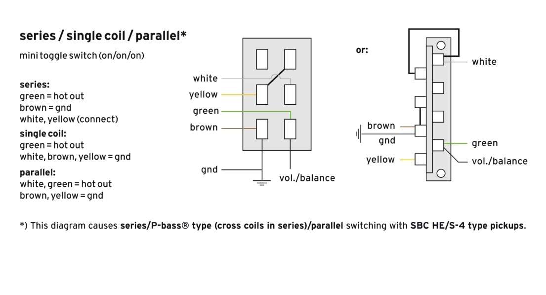
IMG_4977.jpg

2. This is the supplied diagram from Delano, what type of mini toggle switch do I need to use the trim pot?

3. How do I determine which value trim pot to use? What specs of the pickups am I looking at?

4. How do I wire the trim pot? I know it goes from the hot output as a volume know(or something like that), but what does that mean? What leads come from what terminal and go to what other terminal?

Thank you in advance for any and all help! I truly appreciate your time!
John

 
1. No. Resistance is resistance, and in this application, there won't be any audible effect from the minor technical things, like the composition of the resistor, or its inductance. Fixed resistors will sound exactly the same as a trim pot, if the values are equal.

2. That's a DPDT On/On/On switch. If you buy it from a switch catalog, it will often be termed SP3T.

3. The resistance isn't critical, since you will be able to adjust it. Start by using the same value pot as the rest of the pots in the circuit.

4. The switching scheme that you posted is not appropriate for what you are trying to do. You will need additional poles to switch the trim pot in and out of the circuit, depending on which position the switch is set to. @RobbieK has the appropriate diagram for this, so hopefully he posts it.
 
1. No. Resistance is resistance, and in this application, there won't be any audible effect from the minor technical things, like the composition of the resistor, or its inductance. Fixed resistors will sound exactly the same as a trim pot, if the values are equal.

2. That's a DPDT On/On/On switch. If you buy it from a switch catalog, it will often be termed SP3T.

3. The resistance isn't critical, since you will be able to adjust it. Start by using the same value pot as the rest of the pots in the circuit.

4. The switching scheme that you posted is not appropriate for what you are trying to do. You will need additional poles to switch the trim pot in and out of the circuit, depending on which position the switch is set to. @RobbieK has the appropriate diagram for this, so hopefully he posts it.

I did notice the SP3T when looking on mouser, and that did throw me off a little, thank you for clearing that up!

What would it be called? A linear taper trim pot? Or something else?

Well hopefully @RobbieK does post that!

Thank you for your help so far, I will be sure to add more questions if I come up with any.
 
I did notice the SP3T when looking on mouser, and that did throw me off a little, thank you for clearing that up!

What would it be called? A linear taper trim pot? Or something else?

Well hopefully @RobbieK does post that!

Thank you for your help so far, I will be sure to add more questions if I come up with any.

Linear taper trim pots would be the thing to search for. They look like this:
P163.jpg
 
  • Like
Reactions: Killed_by_Death
Hmm, I've never wired a parallel/single/series+attenuator with an on-on-on mini toggle. As others have said, you'll need an extra pole or two, and FWIW, last time I bought a 4-pole on-on-on mini toggle, it was around $30. And you'll need one for each pickup of course... I've wired many rotary switches with this. And also many 3 and 4 pole toggles for parallel/series+atten. (Without the single coil option).

Actually before we go on, just to clarify, do you want one switch to operate both pickups? Or a switch for each pickup?
 
Hmm, I've never wired a parallel/single/series+attenuator with an on-on-on mini toggle. As others have said, you'll need an extra pole or two, and FWIW, last time I bought a 4-pole on-on-on mini toggle, it was around $30. And you'll need one for each pickup of course... I've wired many rotary switches with this. And also many 3 and 4 pole toggles for parallel/series+atten. (Without the single coil option).

Actually before we go on, just to clarify, do you want one switch to operate both pickups? Or a switch for each pickup?

Thank you for getting involved Robbie!

It will be one switch for each pickup. This will be my only bass so, $30 a switch is fine. Whatever it takes to have the most useable options.
 
These from all parts are what you need. These can be called different things. Technically they are a 2-throw switch, but they have 3 positions. You need an "on-on-on" switch. Be aware that there are similar looking (and much cheaper) switches that have a centre-off, IOW "on-off-on". These won't work for this.

I'm not sure if there's a standard way of manufacturing these. The centre position shorts an opposite pair of contacts from both throws, and could feasibly be manufactured either way. That's why I've put the "Middle Pos" diagram there. You should test that your switches have this contact pattern when set in the centre position. A switch made the other way will work fine, but you'll have to rethink the diagram.

scan0003.jpg

The left half of the switch is a totally standard series/single/para switch. If you think through that extra third pole, the two resistors are effectively out of the circuit for the parallel and single coil settings. I'd recommend trying a pair of 100K resistors first. This will give 6dB of attenuation. If the series sound is too quiet, change Rx to 82K or even 68K. Or make Ry bigger, say 120K or 150k. Do the opposite if the series sound is too loud with the pair of 100K resistors. The pair should add up to 200K-250K.

You could also try a temporary 250K linear pot, then measure it and put in two closest fixed resistors. Actually, that's the way I'd do it. It will save time, and also save heating and reheating your $33 switches too much!

You will have to try all this with both pickups in place. Blending passive pickups with series parallel switches etc will create a complex set of interactions/loadings, and really, you'll have to experiment. Personally, I'd use an active blend control so each pickup "sees" a constant impedance. Adding passive attenuation to the series sound will also dull its treble response slightly. But hey, IME if you want a bright tone, you switch to parallel or single... :thumbsup:

The A coil is the one that will be on for the single coil setting. You should make sure that A is a north coil for one pickup and a south coil for the other. That way, they will hum-cancel when both are set to single coil. FWIW, I'd recommend having the A coil from the bridge pickup installed furthest from the bridge for a slightly fuller tone.
 
These from all parts are what you need. These can be called different things. Technically they are a 2-throw switch, but they have 3 positions. You need an "on-on-on" switch. Be aware that there are similar looking (and much cheaper) switches that have a centre-off, IOW "on-off-on". These won't work for this.

I'm not sure if there's a standard way of manufacturing these. The centre position shorts an opposite pair of contacts from both throws, and could feasibly be manufactured either way. That's why I've put the "Middle Pos" diagram there. You should test that your switches have this contact pattern when set in the centre position. A switch made the other way will work fine, but you'll have to rethink the diagram.

View attachment 1180914
The left half of the switch is a totally standard series/single/para switch. If you think through that extra third pole, the two resistors are effectively out of the circuit for the parallel and single coil settings. I'd recommend trying a pair of 100K resistors first. This will give 6dB of attenuation. If the series sound is too quiet, change Rx to 82K or even 68K. Or make Ry bigger, say 120K or 150k. Do the opposite if the series sound is too loud with the pair of 100K resistors. The pair should add up to 200K-250K.

You could also try a temporary 250K linear pot, then measure it and put in two closest fixed resistors. Actually, that's the way I'd do it. It will save time, and also save heating and reheating your $33 switches too much!

You will have to try all this with both pickups in place. Blending passive pickups with series parallel switches etc will create a complex set of interactions/loadings, and really, you'll have to experiment. Personally, I'd use an active blend control so each pickup "sees" a constant impedance. Adding passive attenuation to the series sound will also dull its treble response slightly. But hey, IME if you want a bright tone, you switch to parallel or single... :thumbsup:

The A coil is the one that will be on for the single coil setting. You should make sure that A is a north coil for one pickup and a south coil for the other. That way, they will hum-cancel when both are set to single coil. FWIW, I'd recommend having the A coil from the bridge pickup installed furthest from the bridge for a slightly fuller tone.

I was looking at those, so happy I am on the right track at least. Ha

When testing with the pot to find useable values, would I be trsting with one pot and splitting the value between two resistors, or would I use two pots to find the value?

Is there a reason to only have the pot temporarily and not permanently?

The preamp in the bass is a Glockenklang 3-band, does this have a active blend control?

Sorry for all the questions, I am wanting to know how and why to do things to gain a full understanding of how these work rather than just what to do. :)
 
Last edited: