
Enjoy the benefits of a premium membership!
Upgrade Account
-
TalkBass has been independent since 1998. Add your voice.
Create a free account to reply to discussions, view embedded media, and browse with fewer display ads.
Join free Log in
Want zero display ads or expanded classifieds tools? Compare plans.
You are using an out of date browser. It may not display this or other websites correctly.
You should upgrade or use an alternative browser.
You should upgrade or use an alternative browser.
More options
Who Replied?
I will. Still figuring out how I'm gonna do that...pretty sure that's all you do! the pickups should still go to the same places
so you cut the traces on the opposite mirror image spots too right?

I would not open up the pot because you can very easily damage the small contact arms that way.
For me, using a safety pin (bent to form a "handle") worked the best for cutting the resistance track.
For me, using a safety pin (bent to form a "handle") worked the best for cutting the resistance track.

Here are the readings with the pot at center indent:
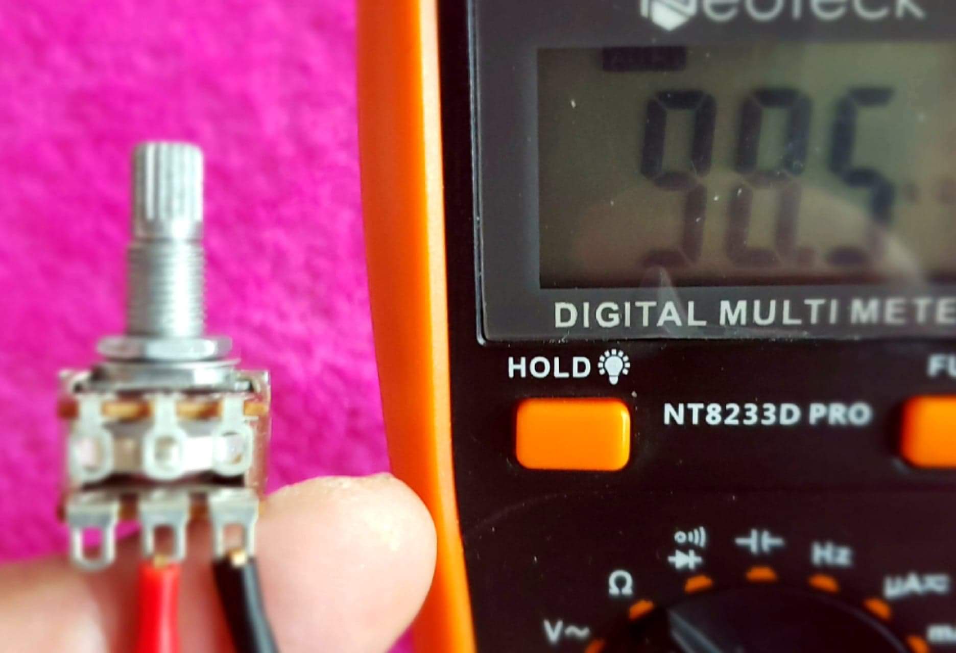
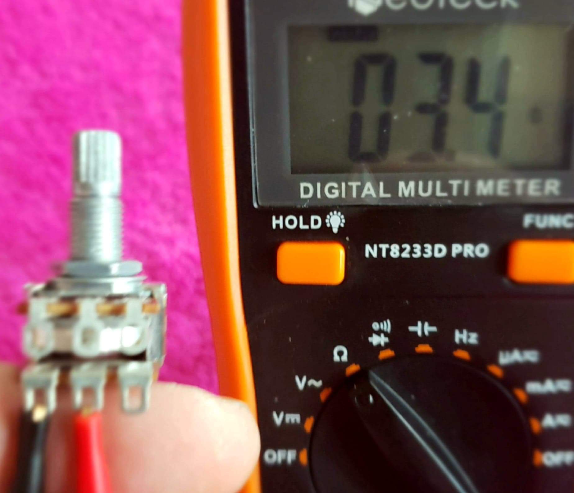
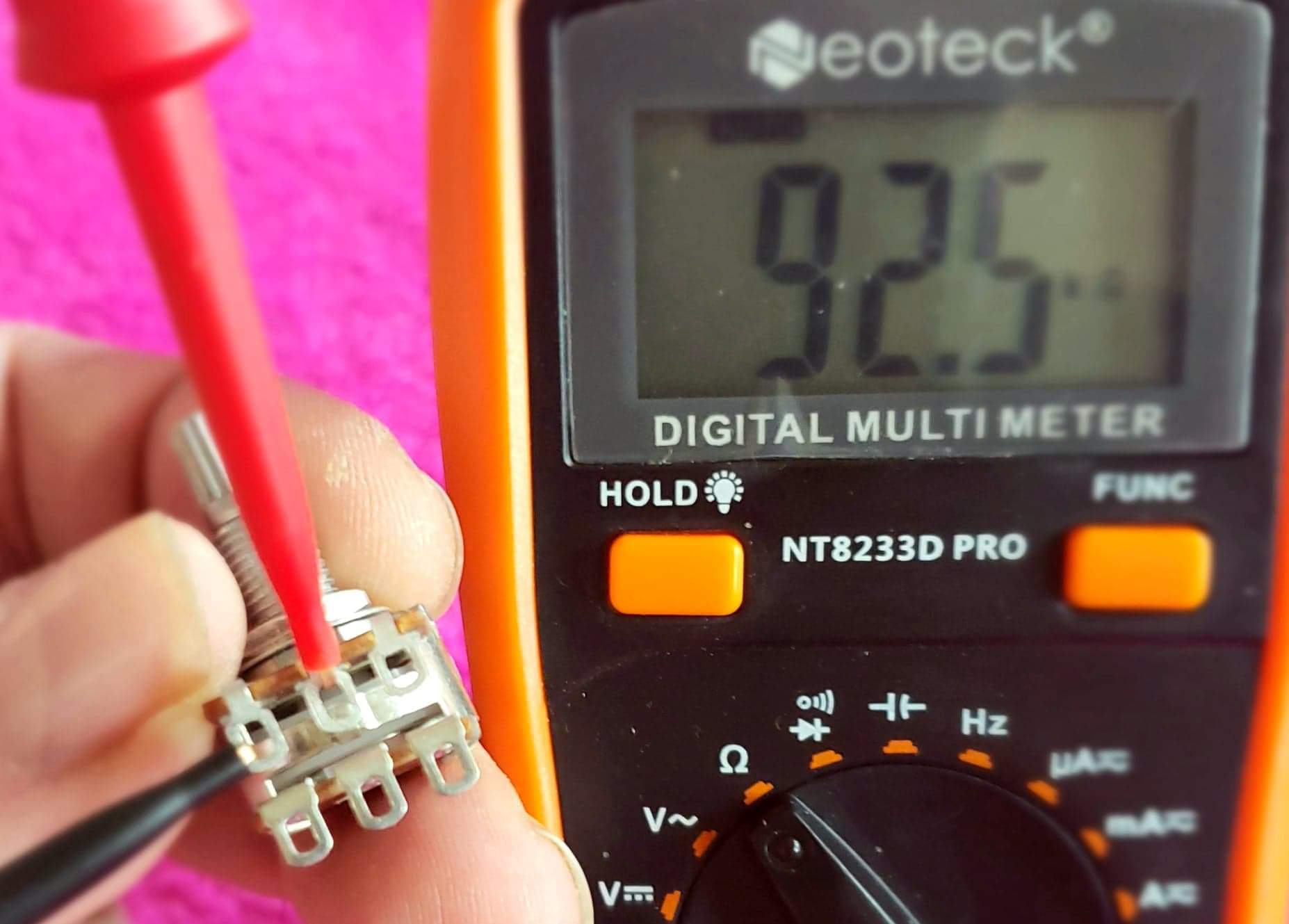
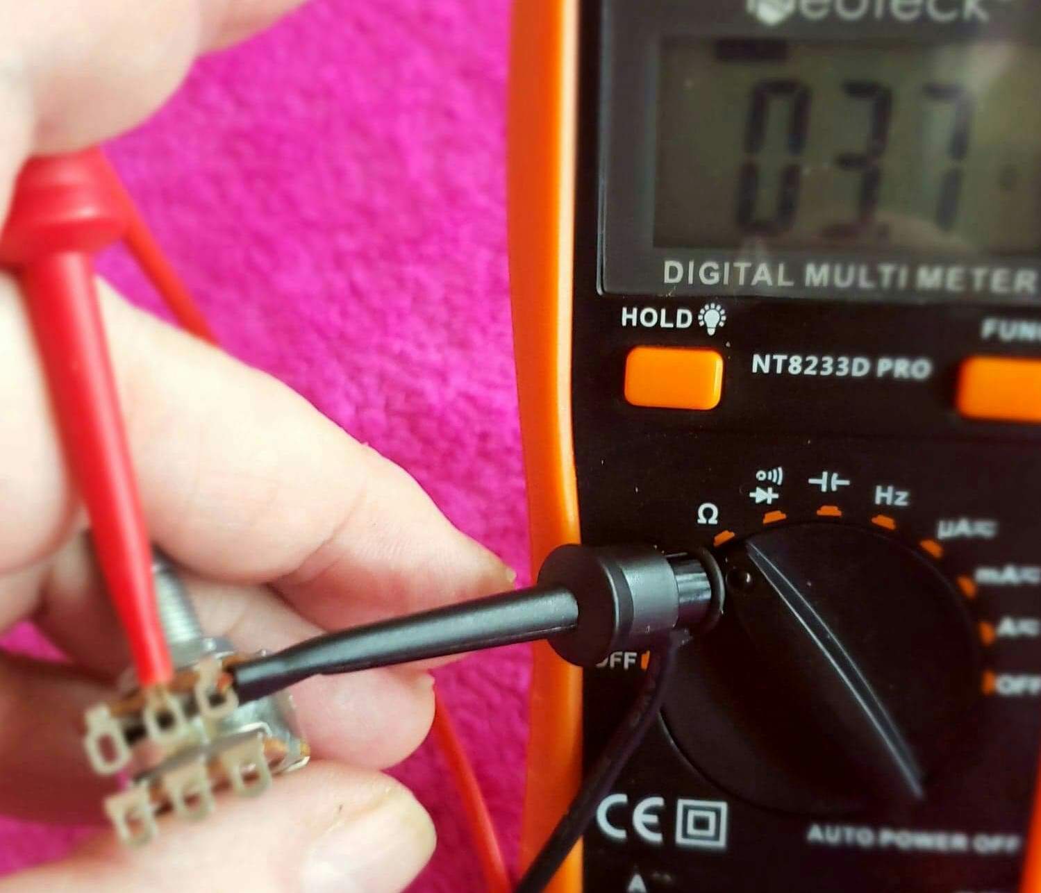
Just triple checking before I cut leads and solder...
Just triple checking before I cut leads and solder...

it'll be the same, think about it for a minuteMy pictures are with the pot inverted. Should have done them the same way you took it, as now I'm confused...
Just look where the black carbon resistance track is. You want to cut at the end of it. The other end will be metal.

I tried the 25k pot both grounded and un-grounded. It works both ways, but un-grounded still allowed a fair amount of signal through from the "off" pickup. I then went ahead and connected the ground wires, and that seems to provide the full range of pickup blending without any extra travel--as determined by lightly taping on the pickups. I'm gonna leave it that way, at least for now. I think that an un-grounded 100k-ohm pot would probably be a bit smoother (in terms of taper/signal ratio) and provide just the right amount of resistance to get the full range of pickup combinations, but so far, I'm not having any problem dialing in the tone I want with the grounded 25k-ohm pot. Of course, that could change when I start gigging with this bass.i should think so yeah (it's been so long since i tried any of this on actual active pickups), but it might not work ungrounded at all; 25k series resistance might not even get noticed by the active pickups, you may have to keep the blend grounded to get any results. there again, the pickups being active should also not get any real tonal loss from the grounding either.
EMG sells an actual active blend pot, 9V powered with two buffered ins and a mixed output like from a mixing board; that might be the best bet.
I considered the EMG active blend pot very briefly, but if I wanted to go that route, I think I would just get an active pre-amp. I generally really appreciate on board pre-amps, but I'm using this bass as kind of a learning project.
There's metal on both ends, top and bottom wafers. I thought I just needed to cut the metal not attached to the jumper.Just look where the black carbon resistance track is. You want to cut at the end of it. The other end will be metal.
nope!Okay, let me ask it this way. Shouldn't I be reading the pot value at center indent here:
you want it as close to a dead short as possible, that's your pickup signal trying to get through to the output. think of it like a 3-way switch, in the middle you want no resistance at all, everything is connected. the pot resistance is what would be (mostly) blocking the signal, and once you cut the traces will be an open circuit, no connection at all.
your pic tells me that you can just cut and wire it the same as in my pics and you should be in business

Thank you for your patience WalterW!! I'm measuring 'resistance', so the pot value is not 'open'. I did "think about it a minute", but I'm used to measuring voltage not ohms. So I will follow your directions exactly. I want to cut the metal as in your pic, right?nope!
you want it as close to a dead short as possible, that's your pickup signal trying to get through to the output. think of it like a 3-way switch, in the middle you want no resistance at all, everything is connected. the pot resistance is what would be (mostly) blocking the signal, and once you cut the traces will be an open circuit, no connection at all.
your pic tells me that you can just cut and wire it the same as in my pics and you should be in business
i guess it's metal?I want to cut the metal as in your pic, right?
it's the carbon track that the middle lug wiper slides along when you turn the knob. you want to cut it just before the spot where the wiper stops when you turn the pot all the way. the wiper contact sliding over the cut is what disconnects it from the track entirely, shutting off the pickup.
Belay my last... Please have pity on my as I know not what I do. I went in after the Carbon trace and succeeded in ruining the pot (but I've got four more). So, I popped the back off to see exactly what everyone is talking about. Here is the mess I made...
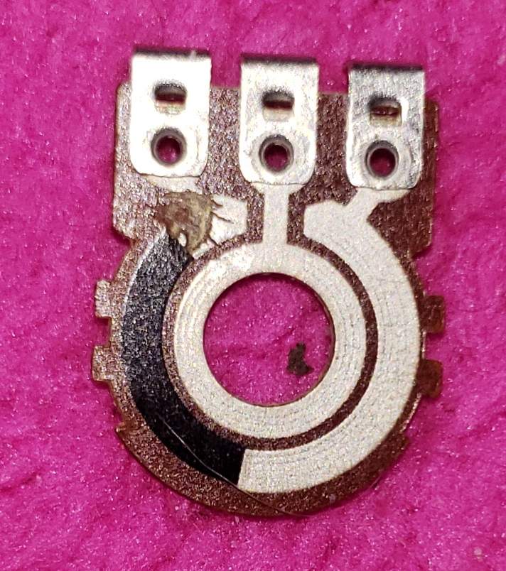
Does anyone have the patience to tell/show me exactly how I want to do this?
Does anyone have the patience to tell/show me exactly how I want to do this?

I suppose white traces are conductive (seeing as wiper ring is made of white stuff), and black is resistive part. You can just connect multimeter in Ohm mode, connect one end to rightmost (as in this pic) lug and then probe at white and black places. It sould read ~ Nominal value close to the left lug.Belay my last... Please have pity on my as I know not what I do. I went in after the Carbon trace and succeeded in ruining the pot (but I've got four more). So, I popped the back off to see exactly what everyone is talking about. Here is the mess I made...
View attachment 3554045
Does anyone have the patience to tell/show me exactly how I want to do this?
If I reason resistance of while and black parts correctly, you are logically doing it right. Just position the cut more precisely:
It is hard to tell where wiper actually lands without seeing it in assembly. So logic is: cut counter-clockwise from wiper stop position.
You can test result with multimeter again, it should say "No connection" (infinite Ohms) when wiper is at stop.
And remember, there is 2nd trace to cut, it migh or might not be on different side. Logic should be same, measure resistance and cut.


