• TalkBass has been independent since 1998. Add your voice.
    Create a free account to reply to discussions, view embedded media, and browse with fewer display ads.
    Join freeLog in
    Want zero display ads or expanded classifieds tools? Compare plans.

Who wouldn't want a 6 - string fretless?

Thank you, I'm quite fond of it too.


well, in the beginning, I almost did. Then I made some 1/4" sanding drums that I simply chuck up in the drill press. Well, I cut some steel rod and glued sandpaper (of various grits) to them with spray adhesive, then put some strapping tape on the ends. This takes care of the hard work at least.


This one has a 16", and the block I got from LMI,

Thanks for the info. That´s indeed an ingenious solution for sanding tight places.

16" is a very pronounced radius for a 6er, is it that you are using a pretty thick fingerboard or is it a rather tight string spacing (or a bit of both)?
If if´s not too much to ask, can you tell me how wide is the LMI block. Vendors omit that info often.
Greatly appreciated!
 
octaedro7 said:
16" is a very pronounced radius for a 6er, is it that you are using a pretty thick fingerboard or is it a rather tight string spacing (or a bit of both)?
If if´s not too much to ask, can you tell me how wide is the LMI block. Vendors omit that info often.
Greatly appreciated!

Sorry I was away for quit a bit.

yes it is a bit tight string spacing, but mostly it's what the client wants. The FB was 1/4" thick before radiusing, so after a CA coat it's probably still 1/4" thick in at the mid point.

It's not or wasn't to much to ask, so if this question still apples the radiused surface of my LMI sanding blocks average 3 1/4".
 
Well I’ve been away from this for a while. This build thread has been held up do to my client trying to get custom strings from his string endorsement company. Finally he’s agreed to go with what I typically use and know will fit. So we’ll be back on this very soon.

Meanwhile I had this little lap-steel commission and it is in the finish stages.
DSCF0121_zps5585485e.jpg


So, soon as this is done the strings should be arriving and well get to mock-up, finish sanding and knob making on the 6-S.


Till next time; happy building. .:D.
 
I was wondering what happenede with this build. Good to see it's not dead. :)

Also, that lapsteel looks really nice. What kind of wood is the FB on it? Walnut and ebony?

By no means is it dead, just a horrible pause.

Yeah, it was the excess I cut off the back of a neck a few years back. It's been floating in the cut-offs waiting for just the right application.
 
Hellooo TB!...

Project “LAP STEEL” with a custom case has been completed, the case proved to be as time consuming as the instrument itself due to the client wanting the case to have detachable legs that get stored in the case allowing him to turn the case into a table to play the lap steel on top of. A couple of pics for you…

005_zps4382d2df.jpg


011_zpseb2d1595.jpg


This is my favorite pic of it in the studio.


Lapsteelnstudio_zpsb9068cbd.jpg


So It’s back to this bass, (and this thread… geezs, it’s been a while.) my goal is to be finished by Christmas, which I think is totally doable.
As of last night, I have entered the finish sanding phase and hope to be putting on oil soon after our Thanksgiving.


I have lots of pics of making the wood knobs, (A virtual “how I do”) which are stack knobs BTW, as if a wood knob without a lathe isn't hard enough.
So… let me gather some photos, compile some info and I’ll be back with all the good stuff.


Should be later tonight, (my night that is… ha, ha.) Talk to you soon. :)
 
Ok, so the fingerboard got several coats of CA but I didn’t get any pics of the process. Nothing crazy, just super thin CA glue liberally spread across the board sanded back and reapplied. I did this about 4 times a day for 4 days going up in sandpaper grit till I got a nice even glass like finish.


So I’ve been working on a repeatable method of making wood knobs without a lathe accurate enough to satisfy my OCD for (sad to say) a number of years, and every time I think I’ve got it, I find something wrong with the knobs produced or the accuracy of the method upon repeat. So, my trials will continue until I satisfy myself or I break down and buy a milling lathe. That said… here’s where I’m at.

This method works quite well for single knob sets with around 0.008 – 0.025 thousands off center and produced acceptable results for this stacked concentric knob set.
I glued some cut-off of wenge and sapele and made 6 - ¾” x ¾” plugs with a tenon cutter for the bottom knob blanks. With the rest of the sapele cut-off, I cut 6 - 5/8” x 28/32” plugs with a standard straight wall plug cutter.

BA-6knobsampstuff001_zpsd5552010.jpg


BA-6knobsampstuff002_zps6634400c.jpg


From here we go to the jig.
This jig got made and modified many, many times only to discover the simplest version, which is simply a clamp, producing the best results so far (not to be fooled by the different versions in some of the photos).
when I tried mounting the clamping portion to a base to be used in a secured stationary position on the drill press, the clamping pressure would angle the blank, like… / / | ( almost undetectable because the entry point is centered) just enough to stop the knobs from sitting level on the pot shaft. When just using the clamp and holding it by hand the angling of the front and back self level better, like… /|\ hope that make sense.


Now here’s some old info from my original notes I’m going to cut and paste together on how to build the clamp. Part (B) - Body) is the clamp, originally there were more parts I found to be less necessary.

The average knob dimensions are 3/4“ x 3/4” with a 1/4“ hole to accommodate a pot shaft and 5/8” counter bore to hide the pot mounting nut, these are the dimensions I will be using.

Let’s start with the clamping portion of this jig. You only have to dig through your scraps for good wood pieces to do this (I don’t like to throw stuff away if there is enough to make something out of it). A piece of alder for part (B) - Body) cut to 1” 17/32” x 5” 28/32” x 1” 17/32” (you can change these dimensions to suit your needs of course). Now mark center on the vertical and horizontal.

woodknobs024_zpseb5fa9b2.jpg

woodknobs025_zps7095a7e3.jpg


On part (B) – Body) continue center mark to back side and one end, also mark horizontal center on back side. Mark a vertical line 3/4” in from each side (if you want to counter sink the carriage bolts, do so be for drilling the 1/4“ holes with the 5/8” forstner bit. I chose to do this; I also counter sunk the front for the washers). Drill two 1/4” holes at marked center point on the ends of the back side of the body.


woodknobs026_zpsdaf13263.jpg

woodknobs027_zps3fea6519.jpg


With a 3/4” forstner bit in the drill press, line up with the center point in the body (part – B) and drill all the way through.

At this point it should look something like this…

Side of body (part – (B)


woodknobs014_zpsf553a8be.jpg


Top of body (part – (B)

woodknobs009_zps22ba8e1a.jpg


Looking at the end with center mark, measure and mark 2/32” on each side of center, totaling 4/32” which is about the kerf width of a standard table saw blade, using your table saw (or band saw which would be more safe) set your fence and rip part (B) – Body) down the center (if you use a table saw for this step please take extreme caution).

woodknobs007_zpsea7bd87f.jpg


woodknobs008_zpsc720c957.jpg


The part on the right in this last photo is one of those "less necessary" parts I spoke of.

Now assemble the body (part – (B) with 1/4“ – 20 carriage bolts, washers, and wing nuts. snug up the wing nuts, and check the fit. At this point you probably know where this is going.


I hate to leave you folks hanging… But, I must sleep now. I’ll do my best to get more of this up quickly.
Till then… Happy building. :)
 
Oh, wow. That lap steel looks fantastic!

What is the case made from? Textured plywood? I have never seen anything like that on flight cases. (The ones I have worked with is a bit more industrial, though...)


I hate to leave you folks hanging… But, I must sleep now. I’ll do my best to get more of this up quickly.
Till then… Happy building. :)


Nah, you can sleep when you get old. ;)


Looking forward to see how you solve the knob problem. I have been struggling with a similar problem (OCD and accuracy... ;) ) and have come up with a very different solution.
 
Thanks guys!

Oh, wow. That lap steel looks fantastic!

What is the case made from? Textured plywood? I have never seen anything like that on flight cases. (The ones I have worked with is a bit more industrial, though...)

yeah, it's covered with tolex.


Oh,Nah, you can sleep when you get old. ;)

I have two kids under the age of 6... well lets just say today wasn't a good day for me, but they had fun! :rolleyes:


Oh,Looking forward to see how you solve the knob problem. I have been struggling with a similar problem (OCD and accuracy... ;) ) and have come up with a very different solution.

I got to know, what is your solution?
 
Moving on…

I made a similar clamp with a 5/8” hole for the 5/8” plugs to be used as the top knob blanks in a very similar process.

Placing the knob blank in the clamping jig bottom up, I shim it up so that it sits in the clamp with about ¼” extra clamp height. After tightening the wing nuts, I then chuck up a ¾” forstner bit in the drill press. Using the clamp walls as a guide, I’ll plunge down just enough to make a center dimple, switch to a 5/8” forstner bit and line up center with the dimple and chew up 4/32” of depth. Seeing as these are stacked knobs I then flipped the blank over and repeated these steps.

BA-6knobsampstuff003_zps6bae192c.jpg

1-BA-6knobsampstuff004_zpsea06fe24.jpg

1-BA-6knobsampstuff005_zpse4278d70.jpg


This is where it gets tricky, for the most part I had just been following up the lead dimples with a ¼” forstner bit, but after close inspection I discovered the pilot brad on the ¼” forstner bit is slightly smaller in diameter and shorter (on my bits anyway) allowing for as much as 1/32” off center. A good brad point bit might be the solution here, but the ones I currently have are cheap and have too much run out, they have served me well to this point, but it might be time to upgrade. A standard twist bit (of which I do have a good quality set of) I found to be too aggressive and can create enough chatter to blow the whole bottom out (the chatter could also be due to the amount of run out on my drill press, I suppose I should look in to that). So my next experiment was with a set of step bits, this seemed to give me the best results to date, but depth is an issue. Depth was not a problem for the bottom stack knob since the hole needs to go all the way through. So I step drilled to 5/16” (well… the first couple were stepped to ¼”, but you get what I’m saying… right?) flipped the knob and stepped from the other side then ran a 5/16” twist bit to clean it up.

BA-6knobsampstuff007_zpsc1175acd.jpg


I’m going to have to stop it here for the night…

Next time we’ll get these spinning, Happy building. :)
 
What bridge did you use on that lap steel? A lap steel is on my short list for future builds, but I have no clue as to what bridge to use.

It's a Duesenberg Multibender. It cost a pretty penny, but sooo worth it.

here's a couple links... :)

Invalid Link Removed

Invalid Link Removed
 
Before we get to the spinning of these knobs, I thought it might be helpful to mention that in the end I will have/need 2 stacked knobs for concentric pots and 1 dummy stack for a push pull pot. Also I have already completed these knobs with satisfactory results, not as dead on accurate as I would like, but adequate. This drawn out explanation of how I went about making these knobs is also taking up the down time of the grueling process of finish sanding before slinging some oil.

So, Let’s get back to it.

When I make wood knobs, I always make twice as many as I need so I have room for mistakes and the ability to choose the best looking of the grope,( I end up with extras most times) At this point I had drilled out 5 of the 6 bottom blanks with 3 good ones, 2 dafunked and 1 back up waiting for tragedy to strike. Next I coated the inside rim created by the recess with super thin CA glue, top and bottom. Once dry (of course, ha, ha) I simply mounted the knob on a ¼” – 20 nut and bolt then chucked the assembly up in the drill press (this turned into a 5/16” nut and bolt by the 3rd one).


BA-6knobsampstuff008_zpsad77d231.jpg

BA-6knobsampstuff009_zps575d70cf.jpg


BA-6knobsampstuff010_zpse802f5f5.jpg


With an assortment of sandpaper (80 – 220), hard and soft sanding blocks, and a fine coarse file at the ready… I turn on the drill press. Starting with the 80 grit on a hard block I just touch the outside surface and try to sand out what ever off center rotation I may have, adding a little more presser and moving the sanding block as it starts to spin more balanced. Then I’ll turn off the drill press and give it a onceover, if there are any stubborn burn marks left over from the plug cutters I repeat this step using the fine coarse file. That usually takes care of it, but if not, I’ll run it with some 60 grit paper on a soft block (I’ve come to love the old pink school erasers to use as sanding blocks with a little give, “soft block”). Next with the 80 grit I’ll work the top and bottom ends. For the end closest to the drill chuck, (sorry no pics of this part) I stack my sanding block on a piece of scrap and pull the handle of the drill press until the knob is below the sanding block. With the sanding block in the path of rotation, I begin to release my pull on the drill press handle letting the knob come up to the sanding block. For the end farthest away from the drill chuck, I do the same thing except pushing down into the sanding block. With that done, I’ll run through the sanding grits wrapped around my pink erasers up to 220.

BA-6knobsampstuff014_zps1aaaa9a5.jpg


X 3

BA-6knobsampstuff016_zps83621766.jpg


So remember the 2 dafunked knob blanks, well… one look real good… once you got past the center,(the hole for the pot shaft) being WAY off. Yeah, as long as that wasn’t important. As luck would have it, it wasn’t so important for one of the knobs in this set, so this blank will become the dummy stack. Back in the jig it goes and with my 5/8” forstner bit, I followed the existing recess and went all the way through the blank.


BA-6knobsampstuff018_zps1cf2baf5.jpg

BA-6knobsampstuff020_zpsf56d3499.jpg


A 5/8” plug cut for the top blanks push in nice and snug. As I pushed it in, I stop 4/32” from the bottom to leave the same recess as the other knobs. More pics?... maybe just one more for tonight.


BA-6knobsampstuff022_zps04f25bef.jpg


There will be more after are US. Thanksgiving holiday.

Therefore, to all of you in the states, Gobble Gobble! To all those in other countries and what not, I hope the best for your holidays that are to come.

Till next time… happy building. .:).
 
- Time laps… :hmm:

- Time laps… :hmm:


Hello everyone, my posts have been a bit sporadic lately. I’m finding it difficult to keep up with everything I’ve got going on and the holydays didn’t help. Anyway, I hope everyone made the best of their holydays and enjoyed themselves. As far as this bass goes, I don’t have much left, as a matter of fact, it’s almost done! So, as much as I wanted to do this knob thing in great detail, I’m going to touch on the important stuff and get this thread up to date (this beginning part I already had typed up, so I left it as is).


Now where was I? Ahh… yes. With the dummy stack turned bottom up (on top of some wax paper), I liberally applied thin CA glue. While letting that dry I turned focus to the brass inserts. Typically, I make wooden knobs with a set screw in conjunction of a soled shaft pot, so a cut of brass tube pressed in the knob is all that’s required. I felt the need to do things differently this time, (I wasn’t about to go changing pots on my prewired preamp harness) the concentric pots main shaft is a split shaft and the secondary is a keyed shaft.
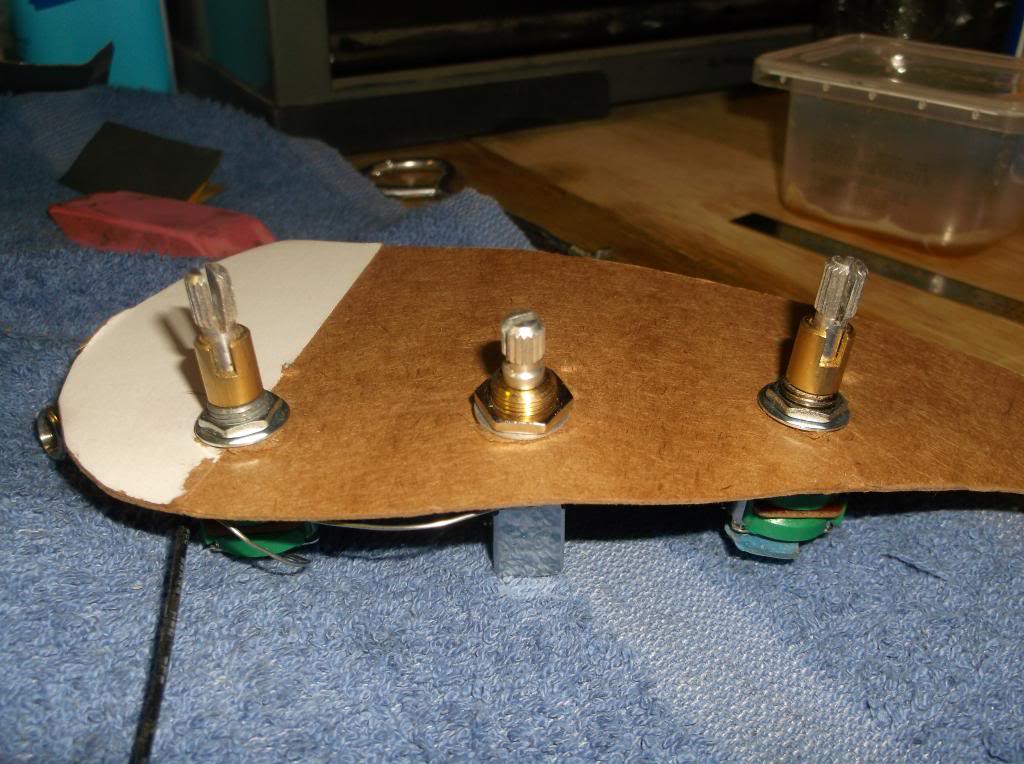
prepots0222_zpsde0e441f.jpg


In the past I have not liked using a set screw type knob on a split shaft, IME I’ve found the knob to be less secure, (due to the compression of the split shaft made by the setscrew) prone to free spinning because the screw has worked itself loose and the rotation to be out of balance, (turning in an oval due to the set screw forcing the knob hard to one side of the shaft). Granted, you could say I’m just splitting hairs here; the oblong rotation is something you feel more than see and probably wouldn’t bother most, but losing a knob because it fell off somewhere just kinda sucks. So here’s what I came up with, for the bottom of the stack, (I tried a few things and simple worked best) I got a corresponding brass tube and drilled a small hole in one side. For lack of better words, the “blowout” from drilling was just enough to work as a key to the shaft and to strengthen it to hold up to use, I simply applied solder from the outside until the “blowout” was filled. A little needle filing and the fit was very snug yet allowed easy operation. There was a bit more to the insert for the top of the stack, again using a corresponding brass tube and a piece of flat brass stock.

First I clamped the tube in a vice to stand it up right and did my best to cut a slot across the top middle with a dremel cut off disc.
BA-6knobsampstuff023_zps872f3c9e.jpg


Rest the flat stock in the slot and solder it together.
BA-6knobsampstuff024_zps11e9ddfd.jpg


The idea here is that when the top knob is pushed on, the flat brass stock will seat in the split stopping the compression of the split and allowing the setscrew to tighten securely and should the screw become loose; the knob will still turn the shaft. The first few times I did this I used flux, (seen in pic) which worked, but… too much of the solder wicked to inside of the tube clogging up the corners and stopping the insert from seating appropriately, not to mention a lot of filing. In the end, turning up the heat on my soldering iron was enough; it still needed a little filing though. The top knobs have such a tight fit they probable don’t need a setscrew but they will get one.

With that done it was it was time to pretty up the dummy stack. First the set screw, (I got pics of me doing this with the top knobs but not this dummy stack) after measuring for the indent on the shaft, I made a mark and dripped some thin CA glue over it to try to prevent too much tear-out. Then placed it in a vice and drilled an under sized hole. Next I flow thin CA in the hole, with a tap chucked up in the drill press I give it some threads. Now I place it on a small mandrel and tighten it down with the set screw. Of course this small mandrel did not begin its life as such; originally it was a spring loaded pin for a bifold closet door.


Top knobs. Using a clamp jig drilled out for the 5/8” plugs, I followed a similar procedure as before. Starting with a 5/8” forstner to establish a center point created by the pilot point of the forstner bit, and then follow the pilot point with a step bit. Here’s where I’m catching everyone up, so on with the onslaught of pics. That’s what we all want anyway, right?. ;).

Here’s the dummy stack before a finale sanding spin and applying finish next to the plastic stack that came with the pre.. I was really surprised to see how tall the supplied knobs were, I made mine a little shorter.
BA-6knobsampstuff027_zps9bd0fe35.jpg


WARNING copy and paste in progress. - after measuring , I made a mark and dripped some thin CA glue over it to try to prevent too much tear-out. Then placed it in a vice and drilled an under sized hole. Next I flow thin CA in the hole, with a tap chucked up in the drill press I give it some threads. Now I place it on a small mandrel and tighten it down with the set screw.


In this shot, I’m tapping for the set screw.
BA-6knobsampstuff028_zps8cfada8b.jpg


Top knob blank, CA glue stain, and “mini mandrel”.

BA-6knobsampstuff029_zpsc7fb0821.jpg


One of the cool features of my affordable drill press, I can tilt the head 90°. So I use it like a lathe (kind-of) when doing these knobs. By no means would it stand up to the requirements of true lathe work, but for simple shaping and sanding it works good. I have done all this in a standard vertical drill press as well, but being able to do this in a horizontal position is convenient, sooo… I’ve been toying with the idea of building a tail chuck and seeing what that dose for me (like a true lathe) but I haven’t yet. FYI, the scrap of ply in front was used as a tool rest.

BA-6knobsampstuff030_zpsfd1d72bd.jpg


I discovered some cheap hobby chisels and reciprocating saw blades worked quite well for my needs. Real high tech, I know.


Cleaning up the bottom…
BA-6knobsampstuff031_zps75141c12.jpg


Cutting to hight, first I define the cut line with bevealed chisel ( I think that’s what you call it)…
BA-6knobsampstuff034_zps47129462.jpg


I introduced the saw blades with the theory of less sideways presser on the drill press and a quicker cut…
BA-6knobsampstuff035_zps8a434fb1.jpg

BA-6knobsampstuff037_zps9c8eb5e9.jpg


Once the excess is holding on by a splinter, I snapped it off...
BA-6knobsampstuff041_zps3a305947.jpg


Then shaved it with the little bevealed chisel a bit. Next, I use a pice of 2” PVC, (that I’ve cut length wise) wrapped with 100 grit to contor what will be the top end. (it’s not wrapped in sandpaper in this pic so the radis can be seen better)…
BA-6knobsampstuff042_zps32a9ab96.jpg


Some more sanding up to… I for get 350… 3 something anyway; and we get a set of rough knob…
BA-6knobsampstuff043_zps5b4c37ec.jpg


Press in the bushings…
BA-6knobsampstuff044_zps93b3d3b5.jpg

BA-6knobsampstuff045_zpsb1a4789f.jpg


Redrill and tap for the set screw, more sanding and refining and…


BA-6knobsampstuff049_zps19c3ff8d.jpg


KNOBS! :hyper:

Wow! That took FOREVER…
 
Miziomix– for all that drill press dose it is quite affordable, at least here in the states anyway. I don’t find to many reasons to tilt the head, but the head also has a radial function and I use that a lot. If your really interested I’ll be happy to send some info so you could try to find it where you are.
Not that a drill press like this is going to increase the quality of your work or anything, I mean come on man, your killing me over here! .:rolleyes:. .;).


Wraub - thank you! Your enthusiasm is much appreciated. :bassist:


As I mentioned, there has been a huge time laps in this thread. This bass has been finished and left the shop about 3 weeks ago. Its new owner is quite happy with it. So wraub, maybe the next one. .;). I didn't get a lot of time for a photo shoot, but I got a few good shots and some good shots with strange lighting.

So here we go…


BA-6finpicsTB1_zps5e738fa3-1.jpg


BA-6finpicsTB2_zps52cfcf7e-1.jpg


BA-6finpicsTB3_zpsb789b131-1.jpg


BA-6finpicsTB4_zpse1810be0.jpg


BA-6finpicsTB5_zpsd3ffe39f-1.jpg


BA-6finpicsTB6_zps87d81851-1.jpg


BA-6finpicsTB7_zps4e78db15-1.jpg


BA-6finpicsTB8_zps84fc7b16-1.jpg


BA-6finpicsTB10_zpsf0185ef8-1.jpg


BA-6finpicsTB9_zpsdb93bebd-1.jpg


I’ve got some more pics to sort through and I’ll try to get some of those up, but for now I hope everyone has enjoyed this thread as much as enjoyed building this bass.

Till next time... happy building! .:).
 
  • Like
Reactions: INTP