Flux, I'm just loving this thread. You really help channel the mad scientist in me. Can't wait to see/hear the "Super P" in action.

Enjoy the benefits of a premium membership!
Upgrade Account
-
TalkBass has been independent since 1998. Add your voice.
Create a free account to reply to discussions, view embedded media, and browse with fewer display ads.
Join free Log in
Want zero display ads or expanded classifieds tools? Compare plans.
You are using an out of date browser. It may not display this or other websites correctly.
You should upgrade or use an alternative browser.
You should upgrade or use an alternative browser.
X-Bass - Experimental 3 Pickup Bass
- Thread starter Flux Jetson
- Start date
More options
Who Replied?
I'll be getting back to this project soon. I kinda have to, my bass is in pieces awaiting the router! I've got some priorities ahead of me right now .... soon ... soon.

So if I were using a Switchcraft 13e instead of a 12a, I would connect the tip to the lifter and the shunt to the other jack?
Also, if I had two, how difficult would it be to wire them both up so you could plug into either jack by itself and get both pickups but separate them if I plug into each?
BTW: this and your mod rig thread are awesome. Really got me thinking too.
Also, if I had two, how difficult would it be to wire them both up so you could plug into either jack by itself and get both pickups but separate them if I plug into each?
BTW: this and your mod rig thread are awesome. Really got me thinking too.
Attachments

I'll get back to you in a few hours on this. I'm smack in the middle of getting some work done (work that pays the bills!) so as soon as I'm done out in the machine shop on the lathe, I'll respond.So if I were using a Switchcraft 13e instead of a 12a, I would connect the tip to the lifter and the shunt to the other jack?
Also, if I had two, how difficult would it be to wire them both up so you could plug into either jack by itself and get both pickups but separate them if I plug into each?
BTW: this and your mod rig thread are awesome. Really got me thinking too.
Thanks for the props though!

Well I totally missed getting the information you asked for me to provide you with yesterday, didn't I! My bad. I'll get to it today, my time has not been my own lately and I got completely overinvolved with an non-bass related issue yesterday.
Sorry .... getting to your questions today.
Fluxoid
Sorry .... getting to your questions today.
Fluxoid
Ok, I've never used a 13E before, from the diagram it appears to me that the lifter/shunt relationship is simply a single pole, single throw switch. In other words it's just a make/break switch that the guitar cord tip opens up without the plug actually contacting the switch in any way (electrically).So if I were using a Switchcraft 13e instead of a 12a, I would connect the tip to the lifter and the shunt to the other jack?
Also, if I had two, how difficult would it be to wire them both up so you could plug into either jack by itself and get both pickups but separate them if I plug into each?
BTW: this and your mod rig thread are awesome. Really got me thinking too.
I cannot think of why you'd want to use that particular switching jack as far as offering any advantage, unless it's something that you happen to have and just wish to use for convenience sake.
Anyhow ...
Yes, if you wire both jacks the same way, and connect a jumper from one jack to the other, either one will serve as a single output for both pickups, OR serve as a dedicated output for both pickups if you use both jacks at once. My method is just easier if you don't want to use two switching jacks. 12A jacks are very easy to locate as well. But if you have 13E jacks on hand or have a good supplier for those then yes that can be wired up so that you have dedicated outputs for each pickup OR have one jack for both pickups. You'd be able to use either jack as the "both pickup output" that way.
As a reference here's my setup again (taken from POST #25 on PAGE 2) ... here's a link to that page/post ....
http://www.talkbass.com/forum/f8/x-bass-experimental-3-pickup-bass-948548/index2.html
So from here down is a copy of the text and pics from that post ........
(begin copy)
The diagram works with the photograph below it. The wiring colors in the diagram don't match the photo, but I think everyone will live through it.
There are several options to this type of setup, you may use a TRS jack (tip-ring-sleeve .... aka "stereo") if you want, but you'd need to construct 3-conductor cabling for that to work. You may also use XLR connectors and use a mic-cable if you wish as well. Whatever. Using two guitar cords is actually easier if you want to use various separate FX-per-pickup. You could use a Mic cable (or a stereo TRS cable) if you want then make a "breakout box" that the cable plugs in to that separates ("splits") the 3-conductor cable into the two separate signal lines. As I said, there are many variations to this theme. Whatever flicks yer thrillswitch.
** GREEN lines always = "grounds" in this diagram.
** The green line running all the way down the right of the components is the same wiring run as the bare-copper wire in the picture below (that is one single wire that I ~threaded~ through each part and soldered at each contact point, it isn't short pieces of wired all patched together .. jsyk). Yea, you could omit this wire and rely on using the jack plate as a grounding bus .... but that is very VERY poor engineering. Should one of the jacks or pots become loose the entire grounding bus's integrity is shot. You are FAR better off just taking the few minutes it requires to actually solder in a ground bus that connects everything's grounds together without any reliance on the control plate as a ground conductor. Doing it as I have done makes a solid grounding bus with absolute certainty.
If you didn't care about screwing up the chrome, soldering a ground lug to the control plate that is then soldered/connected to the ground bus would also be a more certain connection for creating the RF shielding. But that is in an ideal situation that disregards the "looks" of the chrome plating on the plate itself. As it is, the ground shield is relying on a solely mechanical connection between the pots and jacks to the plate. Uh .. "good enough" I guess, it'll have to do.
** GREY lines are the white wires coming from your pickups.
** Make sure to sand the areas on the pot-bodies where you intend to solder on them before you solder. Otherwise you may not obtain a proper solder connection. The roughed-up sanded area also gives something for the solder to grab on to.
**BE CAREFUL so as to not get any sanding dust or metal particles inside of the pot (it can get in through that tiny open -slot- right there by the pot's solder terminal). So stuff a piece of wadded-up paper (or something) into that region there to prevent any crud from getting into the pot's workings BEFORE you sand on the bodies. This is important if you do not want "scratchy-sounding" controls.
THE DIAGRAM ABOVE CORRESPONDS WITH THE PICTURE BELOW (the wiring colors do not match at all, but the layout is exactly the same):
(end of copied text and pics)
So the only tactical advantage I can see using the Switchcraft 13E jacks is that you'll be able to use either jack as the "single cord output". Two 13E jacks may be more costly though. On the other hand if you have some 13Es already then ~yes~ they can be used to do the same thing my setup does using a #12A and a #11.
If you still wish to use the two 13E jacks and you need help with the wiring, let me know and I can draw up a wiring diagram similar to the one above for you.
I hope this has been helpful.
..... BTW: this and your mod rig thread are awesome. Really got me thinking too....
That is the entire point. Well, one of the points. I hope to inspire, as well as share, as well as get readers thinking to the point that suggestions and/or questions are generated that might lead me to new roads, which may perhaps provide better/more efficient ways of doing things.
I'm glad these two threads have helped you! I know they certainly help me!

Ok, I'm about ready to begin with the mods on the X-Bass. The last 2 months have been one distraction after another. I have stabilized my life somewhat and can now move forward with projects. Well, almost. A few more days to get the last bits of mess swept up and I'll at last have some time to devote to projects. I'm tearing down the X-Bass today and getting it ready for routing out the pickup cavity.
Do NOT expect a nice ~shaped~ hole. Prepare yourself to see pretty much a cavernous ditch that will provide me unencumbered access to the entire pickup area so that I may mount any type of pickup in any location. I'm going to use a drill press, some wood chisels, and a Dremel to get this done. I don't want to use this as my first experience with a router. I may use the router to do some other shaping and such later with it, but for now I don't wish to complicate this project with a learninbg curve on a new power tool.
I've been practicing with wood chisels on 2x4s for a few weeks now, and I've come to learn that they are VERY exquisite tools. When I first began to learn metalworking, I learned how to use files and hacksaws WAY before I was placed in front of a mill or lathe. I find that philosophy to be a sound practice.
So I'll prepare one of my drill presses for the BIG HOGGAGE, and then I'll use wood chisels and a Dremel to do the final cavity shaping. Chickening out? Some may say so. I call it staying in my comfort zone to move a project forward rather than creating more problems than I solve by trying to use a VERY powerful power tool that I am unfamiliar with under the guise of "doing it faster". I'd rather do it slower and ensure good results. I'll use the router soon enough, after I use it on things less sensitive to mistakes on projects where screwups present less important consequences.
Besides, cash is very tight right now, andwhen I go to buy router bits I want to get good ones, not cheap crap just to get a project done.
Ok, enough rationalizing right?
I have 2 complete sets of Duncan Design J bass pickups, as well as a cheap-ass P-bass pickup set that I got on Ebay. So I have ~that much~ to get started with. That is enough to test out a few combinations and ideas, namely the "Super P" P-bass + J-bass pickup arrangement (I'm excited about that system). As money comes in I'll add a few other pickups to the tests. I am curious about adding a Music Man pickup into the fray, so I'll keep eyes open on Ebay for one of those.
Ok, babbling again.
Pics soon.
Thanks.
Do NOT expect a nice ~shaped~ hole. Prepare yourself to see pretty much a cavernous ditch that will provide me unencumbered access to the entire pickup area so that I may mount any type of pickup in any location. I'm going to use a drill press, some wood chisels, and a Dremel to get this done. I don't want to use this as my first experience with a router. I may use the router to do some other shaping and such later with it, but for now I don't wish to complicate this project with a learninbg curve on a new power tool.
I've been practicing with wood chisels on 2x4s for a few weeks now, and I've come to learn that they are VERY exquisite tools. When I first began to learn metalworking, I learned how to use files and hacksaws WAY before I was placed in front of a mill or lathe. I find that philosophy to be a sound practice.
So I'll prepare one of my drill presses for the BIG HOGGAGE, and then I'll use wood chisels and a Dremel to do the final cavity shaping. Chickening out? Some may say so. I call it staying in my comfort zone to move a project forward rather than creating more problems than I solve by trying to use a VERY powerful power tool that I am unfamiliar with under the guise of "doing it faster". I'd rather do it slower and ensure good results. I'll use the router soon enough, after I use it on things less sensitive to mistakes on projects where screwups present less important consequences.
Besides, cash is very tight right now, andwhen I go to buy router bits I want to get good ones, not cheap crap just to get a project done.
Ok, enough rationalizing right?
I have 2 complete sets of Duncan Design J bass pickups, as well as a cheap-ass P-bass pickup set that I got on Ebay. So I have ~that much~ to get started with. That is enough to test out a few combinations and ideas, namely the "Super P" P-bass + J-bass pickup arrangement (I'm excited about that system). As money comes in I'll add a few other pickups to the tests. I am curious about adding a Music Man pickup into the fray, so I'll keep eyes open on Ebay for one of those.
Ok, babbling again.
Pics soon.
Thanks.
Flux, take this in the positive way it is intended...
You are a FREAK!!!
I love this thread and I cannot wait to see and hear what you come up with. I need to read through the whole thing a few more times before I ask any questions. There is so much information and awesomness that it's impossible to absorb everything in one pass...
Keep up the good work.
You are a FREAK!!!
I love this thread and I cannot wait to see and hear what you come up with. I need to read through the whole thing a few more times before I ask any questions. There is so much information and awesomness that it's impossible to absorb everything in one pass...
Keep up the good work.

I can understand your hesitation about using the router. They used to scare the hell out of me until I started using it in a more conservative manner. You can lay out the perimeter lines for your rout and then start cutting 1/8" deep at a time. The router won't fly away and kill you and it will be easy to control. Keep setting the depth 1/8" lower until you get to the desired depth. You can then use your Dremel to finish the edges.
Of course building a template is better but you need additional router accessories to be able to use them.
Rick B.
P.S. Don't lock the router in the 'on' position because if it gets away from you it might destroy all of mankind.
Of course building a template is better but you need additional router accessories to be able to use them.
Rick B.
P.S. Don't lock the router in the 'on' position because if it gets away from you it might destroy all of mankind.
Heheh ...I can understand your hesitation about using the router. They used to scare the hell out of me until I started using it in a more conservative manner. You can lay out the perimeter lines for your rout and then start cutting 1/8" deep at a time. The router won't fly away and kill you and it will be easy to control. Keep setting the depth 1/8" lower until you get to the desired depth. You can then use your Dremel to finish the edges.
Of course building a template is better but you need additional router accessories to be able to use them.
Rick B.
P.S. Don't lock the router in the 'on' position because if it gets away from you it might destroy all of mankind.
I'm not ~afraid~ of it per se, I've been a metalworker and welder/fabricator since I was about 13 (I'm 52). So I'm very used to using high powered high rpm angle grinders (which can remove a foot or a kneecap in a blink), I've also used chainsaws and even the mighty bowsaw for a living for a while. So it's not that I'm so much afraid of the router, moreso it's that I respect it for what it can do (and UNdo!). I just want to get more aquainted with how it handles in given situations before I use it on something that would be sensitive to a rookie mistake. If I screw up on a home-project or a shelf or something it's no big deal, but if it gets away from me a little on my bass I'll be forever reminded that I should have had more experience with it before I used it every time I pick my bass up!
So it's more like I respect my inexperience and would rather get better with it before I use it on something ~good~. Besides I still need to buy some good bits yet.
I'll hack out the pickup cavity with the drill press and wood chisels, and after I settle on a pickup configuration I may clean up the installation with the router later.

Haahaa!Flux, take this in the positive way it is intended...
You are a FREAK!!!
I love this thread and I cannot wait to see and hear what you come up with. I need to read through the whole thing a few more times before I ask any questions. There is so much information and awesomness that it's impossible to absorb everything in one pass...
Keep up the good work.
It's all good ... I take it as a compliment to be honest!I'll be posting forward momentum soon! And as promised I'll do SoundCloud tracks and hopefully realtime analyzer screenshots as well. I went ahead and bought a computer VST program called TrueTRA. It's a screen displayed oscilloscope and realtime analyzer. So it measures the frequency bands and displays them on a graph on the screen, a lot like what you see when you play music through Window Media Player. Y'know the rising and falling lines that show what frequencies are how loud.
I'll get a control ("before") done first, then that may be compared to any tests ("after") done as I add and change pickup configurations.
And just to head off anyone that wants to tell me I'm tearing up a good bass, I actually bought this bass for this precise purpose. I did so to get tests done so that I can actually build "the last bass I'll ever buy". Once I gather the data and decide on a pickup configuration the idea is to order a Warmoth bass body and have them rout the body to my specifications. Specs gathered and learned from this series of tests.
I'm only sharing these tests with the forum in hopes that others may find the data (and perhaps my conclusions) useful.

... Yes, if you wire both jacks the same way, and connect a jumper from one jack to the other, either one will serve as a single output for both pickups, OR serve as a dedicated output for both pickups if you use both jacks at once. My method is just easier if you don't want to use two switching jacks. 12A jacks are very easy to locate as well. But if you have 13E jacks on hand or have a good supplier for those then yes that can be wired up so that you have dedicated outputs for each pickup OR have one jack for both pickups. You'd be able to use either jack as the "both pickup output" that way.
...
I hope this has been helpful.
It worked exactly as planned, I now have a stereo bass and if for some strange reason I loan it out (unlikely) it won't matter which jack gets plugged in for mono signal.
I won't post pictures because the solder job is terrible, my hands aren't as steady as they use to be. I might look into getting a local pro to redo it cleanly. Thanks for the help.
This is great news. I love it when something different works out well. I'm glad that it came out just like you had planned it, and I am glad that I was able to offer a little encouragment to build a little confidence in you to allow you to move forward with your idea.It worked exactly as planned, I now have a stereo bass and if for some strange reason I loan it out (unlikely) it won't matter which jack gets plugged in for mono signal.
Thanks for the help.
Very well then. Carry on!
I finally got the hardest part done. Since I decided to not use my router on this, I was able to leave the neck attached, the bridge installed, and the pickups and control plate installed.
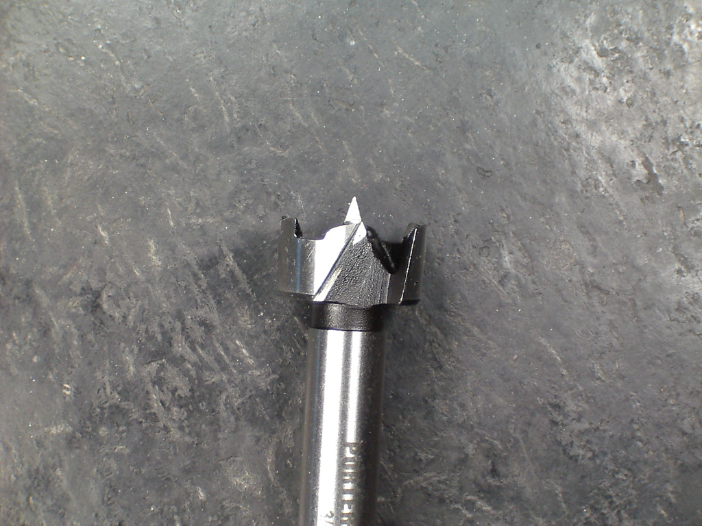
I used a Porter Cable 3/4 inch Forstner bit. I used a bench grinder and gound off the guide point from the bit before I used it to hog out the bulk of the material in the new pickup cavity. I did this so there wouldn't be all of these little divots in the center of each hogged out hole from the guide tip.
First I loosely set the pickups I wished to use on the bass in their approximate locations. I then put down painter's tape in a rectangle to mark where I wanted material removed. I also taped the pickups down to the body out of the way of where I would be working on the new cavity.

I then placed a thin piece of cardboard (from a used up desk blotter calendar) on the drill press table to protect the body. After chucking up the Forstner bit, I used the existing neck pickup cavity as a depth guide. I lowered the quill down untill the bit touched the bottom of the neck pickup cavity, then locked the depth setter. Now I could just pull on the handle until it wouldn't move any more and I would know that each hole was exactly the right depth and each hogger hole would be of uniform depth.
I raised the quill back up, started the drill press motor, and began to reef out the area I had previously marked with tape, one hole at a time. I held the body down with my left arm while I operated the quill feed with my right arm. The body remained stable and didn't try to jump or chatter once while I moved from hole to hole.


After I removed as much material as I could safely remove with the modified forstner bit in the drill press, I then removed the bass from the drill press and finished the cavity with wood chisels. I'm new to using all of this "wood stuff" so I wasn't expecting much, just a cavity that was the right depth and halfway squared sides.
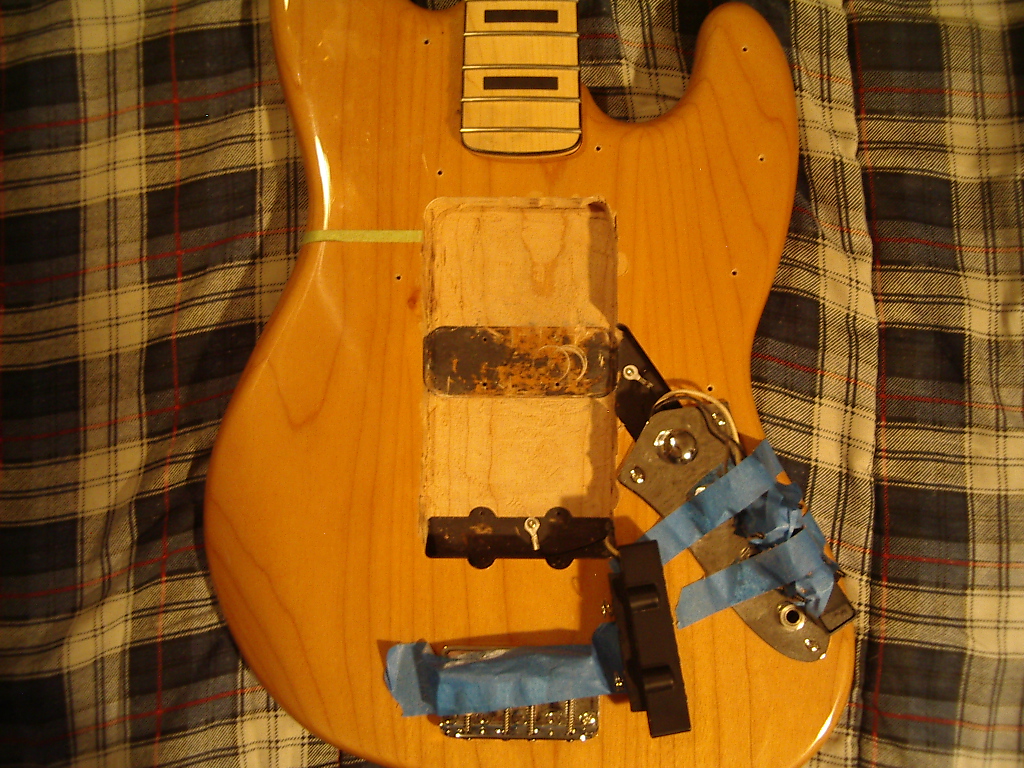
The green pinstripe tape marks the imaginary "24th fret" (aka 2nd harmonic) which is exactly half the distance between the 12th fret and the bridge (34 inch scale bass is 17" to the 12th fret, which means the 24th fret would be half of 17 ... that's 8.5 inches. So that tape line is 8.5" from the 12th fret). That's the centerline of one of the new pickups that will most likely be installed. This is also where Rickenbacker installs their neck pickups on their 4001/4003 basses. So that tape line marks the approximate centerline of one of the new single coil pickups going into the new cavity.
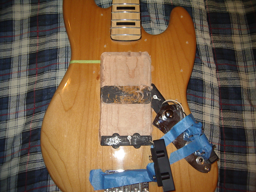

The depth is the same as the cavity that the factory cut out for the stock neck pickup. If I need more depth it will be no problem to remove more material.
I still need to remove a little bit for the little ~ears~ on the P bass pickups, but I'll do that after I get their 1st positions marked.
CONTINUED NEXT POST ......
I used a Porter Cable 3/4 inch Forstner bit. I used a bench grinder and gound off the guide point from the bit before I used it to hog out the bulk of the material in the new pickup cavity. I did this so there wouldn't be all of these little divots in the center of each hogged out hole from the guide tip.
First I loosely set the pickups I wished to use on the bass in their approximate locations. I then put down painter's tape in a rectangle to mark where I wanted material removed. I also taped the pickups down to the body out of the way of where I would be working on the new cavity.
I then placed a thin piece of cardboard (from a used up desk blotter calendar) on the drill press table to protect the body. After chucking up the Forstner bit, I used the existing neck pickup cavity as a depth guide. I lowered the quill down untill the bit touched the bottom of the neck pickup cavity, then locked the depth setter. Now I could just pull on the handle until it wouldn't move any more and I would know that each hole was exactly the right depth and each hogger hole would be of uniform depth.
I raised the quill back up, started the drill press motor, and began to reef out the area I had previously marked with tape, one hole at a time. I held the body down with my left arm while I operated the quill feed with my right arm. The body remained stable and didn't try to jump or chatter once while I moved from hole to hole.
After I removed as much material as I could safely remove with the modified forstner bit in the drill press, I then removed the bass from the drill press and finished the cavity with wood chisels. I'm new to using all of this "wood stuff" so I wasn't expecting much, just a cavity that was the right depth and halfway squared sides.
The green pinstripe tape marks the imaginary "24th fret" (aka 2nd harmonic) which is exactly half the distance between the 12th fret and the bridge (34 inch scale bass is 17" to the 12th fret, which means the 24th fret would be half of 17 ... that's 8.5 inches. So that tape line is 8.5" from the 12th fret). That's the centerline of one of the new pickups that will most likely be installed. This is also where Rickenbacker installs their neck pickups on their 4001/4003 basses. So that tape line marks the approximate centerline of one of the new single coil pickups going into the new cavity.
The depth is the same as the cavity that the factory cut out for the stock neck pickup. If I need more depth it will be no problem to remove more material.
I still need to remove a little bit for the little ~ears~ on the P bass pickups, but I'll do that after I get their 1st positions marked.
CONTINUED NEXT POST ......
Here's a few of the configurations I am thinking about trying ....
CONFIG-1: With it's centerline located in the stock Jazz bass beck position is the "Super P" pickup arrangement I want to try. Note that with the "Super P" array there is a P pickup is ~split~ with a Jazz bass neck pickup placed between the two pickup halves of the P bass pickups. There is also a Jazz bass neck pickup placed in the "24th Fret" location (I call that spot "F24"). And a Jass bass bridge pickup in the standard location near the bridge.

CONFIG-2: Same as CONFIG-1 except notice that the P pickups are swapped around meaning the treble pickup is further back than the bass pickup.

CONFIG-3: Pretty much the same as #1 and #2, except notice the P pickup is not being split by the Jazz bass neck pickup, and the P bass pickup is closer to the neck than the J pickup.
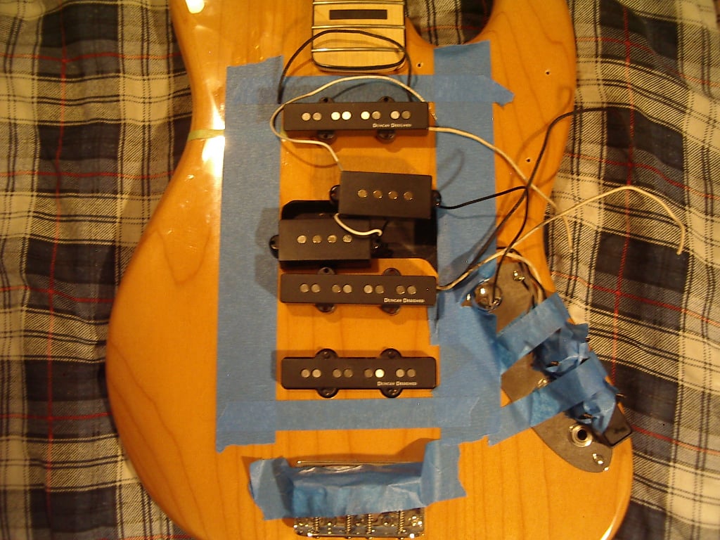
CONFIG-4: The P bass pickup is now closer to the bridge.
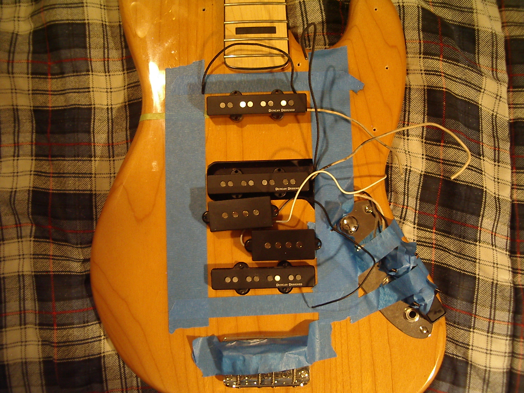
CONFIG-5: Same as CONFIG-4 except the P bass pickups are now swapped around again, with the Jazz bass pickup closer to the neck and the P bass pickup closer to the bridge.

CONFIG-6: Two Jazz bass pickups in their factory stock positions, with an extra Jazz bass bridge pickup located at F36 (imaginary fret #36 located in the 3rd harmonic location), and a P bass set located at #F24 and they're swapped around again.

That's just some of the setups I'll be trying out. There will be others, there is no doubt about that.
To make wiring easy and to make it simple for me to change configurations of series to parallel I'll be wiring each pickup's wires into a terminal strip. That way all I need to do to change the situation around is loosen the set screws, reconfigure the pickup wires (and/or add jumper links and/or grounding wires), tighten the set screws and call it done. Then wires connected to a few jacks and plugs will be connected to the opposite side of the terminal strip and then ultimately to the pickup switching array that I've outlined in great detail in the X-Rig thread (see link in my signature). A total Zero Soldering pickup swapping setup that makes doing tests with the X-Bass much MUCH simpler. This terminal strip was less than $4 at Radio Shack. The control plate and the controls/jacks will be removed for most of the duration of the X-Bass Tests, all the while the pickups will be solderlessly connected to the T-strip.

I'll shoot plenty of pictures of the pickups all mounted up and the wiring setup as well. First things first I need to finish getting the cavity done up, then I'll mount the pickups (after I obtain about ten more pickup mounting screws). I have plenty of pickup mounting foam.
Many notes will be taken, and even more pictures will be shot. As mentioned previously I'll be taking pictures of screenshots of the TrueRTA computer o-scope as well as recording SoundCloud tracks to go along with configuration photos and hand written notes.
The idea here is NOT to make a bass with a bazillion pickups. The idea is to try many configurations and reduce the number of pickups to the least amount required needed to get the job done. Once the final configuration is discovered it will be used when ordering a new Warmoth body to build "the last bass guitar I'll ever buy".
The X-Bass Tests will provide the data needed to construct that bass.
CONFIG-1: With it's centerline located in the stock Jazz bass beck position is the "Super P" pickup arrangement I want to try. Note that with the "Super P" array there is a P pickup is ~split~ with a Jazz bass neck pickup placed between the two pickup halves of the P bass pickups. There is also a Jazz bass neck pickup placed in the "24th Fret" location (I call that spot "F24"). And a Jass bass bridge pickup in the standard location near the bridge.
CONFIG-2: Same as CONFIG-1 except notice that the P pickups are swapped around meaning the treble pickup is further back than the bass pickup.
CONFIG-3: Pretty much the same as #1 and #2, except notice the P pickup is not being split by the Jazz bass neck pickup, and the P bass pickup is closer to the neck than the J pickup.
CONFIG-4: The P bass pickup is now closer to the bridge.
CONFIG-5: Same as CONFIG-4 except the P bass pickups are now swapped around again, with the Jazz bass pickup closer to the neck and the P bass pickup closer to the bridge.
CONFIG-6: Two Jazz bass pickups in their factory stock positions, with an extra Jazz bass bridge pickup located at F36 (imaginary fret #36 located in the 3rd harmonic location), and a P bass set located at #F24 and they're swapped around again.
That's just some of the setups I'll be trying out. There will be others, there is no doubt about that.
To make wiring easy and to make it simple for me to change configurations of series to parallel I'll be wiring each pickup's wires into a terminal strip. That way all I need to do to change the situation around is loosen the set screws, reconfigure the pickup wires (and/or add jumper links and/or grounding wires), tighten the set screws and call it done. Then wires connected to a few jacks and plugs will be connected to the opposite side of the terminal strip and then ultimately to the pickup switching array that I've outlined in great detail in the X-Rig thread (see link in my signature). A total Zero Soldering pickup swapping setup that makes doing tests with the X-Bass much MUCH simpler. This terminal strip was less than $4 at Radio Shack. The control plate and the controls/jacks will be removed for most of the duration of the X-Bass Tests, all the while the pickups will be solderlessly connected to the T-strip.
I'll shoot plenty of pictures of the pickups all mounted up and the wiring setup as well. First things first I need to finish getting the cavity done up, then I'll mount the pickups (after I obtain about ten more pickup mounting screws). I have plenty of pickup mounting foam.
Many notes will be taken, and even more pictures will be shot. As mentioned previously I'll be taking pictures of screenshots of the TrueRTA computer o-scope as well as recording SoundCloud tracks to go along with configuration photos and hand written notes.
The idea here is NOT to make a bass with a bazillion pickups. The idea is to try many configurations and reduce the number of pickups to the least amount required needed to get the job done. Once the final configuration is discovered it will be used when ordering a new Warmoth body to build "the last bass guitar I'll ever buy".
The X-Bass Tests will provide the data needed to construct that bass.


Why don't we have a pickup per string i.e. orientate a lipstick style pickup 90 degrees from the norm.
That way you have a magnetic field map of each string.
Just talking out loud. I'm not sure how this would help.
Davo
That way you have a magnetic field map of each string.
Just talking out loud. I'm not sure how this would help.
Davo

Lipstick pickups arranged longitudinally? You've been looking at Italia Modulo basses, haven't you? 
The problem with that arrangement is there's loads of string pull. There's a greater magnetic force exerted on the strings because the magnets are pulling on a longer bit of each string. The pickups would have to be sunk deeper into the rout to avoid the effect
Then there's the problem of aperture (the magnetic sensing area). The wider the aperture the more the signal you collect is "averaged" and the sound usually gets less trebly. There's a good chance things might get muddy. However, since this is a bathtub rout, lengthwise pickups closer to the bridge might work without losing a lot of the treble.
Flux, you got a fourth Jazz pickup somewhere in there to try this out?
The problem with that arrangement is there's loads of string pull. There's a greater magnetic force exerted on the strings because the magnets are pulling on a longer bit of each string. The pickups would have to be sunk deeper into the rout to avoid the effect
Then there's the problem of aperture (the magnetic sensing area). The wider the aperture the more the signal you collect is "averaged" and the sound usually gets less trebly. There's a good chance things might get muddy. However, since this is a bathtub rout, lengthwise pickups closer to the bridge might work without losing a lot of the treble.
Flux, you got a fourth Jazz pickup somewhere in there to try this out?

This is getting more interesting all the time.
I am a bit puzzled by the "obverse mounted" P bass pickup configuration, though. I have always thought that mounting the treble pickup closer to the bridge than the bass part was the normal Fender P bass way.
For some reason it seems you consider this to be "obverse".
I am confused...
I am a bit puzzled by the "obverse mounted" P bass pickup configuration, though. I have always thought that mounting the treble pickup closer to the bridge than the bass part was the normal Fender P bass way.
For some reason it seems you consider this to be "obverse".
I am confused...
This is getting more interesting all the time.
I am a bit puzzled by the "obverse mounted" P bass pickup configuration, though. I have always thought that mounting the treble pickup closer to the bridge than the bass part was the normal Fender P bass way.
For some reason it seems you consider this to be "obverse".
I am confused...
Error. Corrected.


