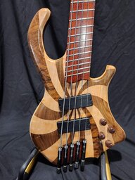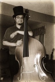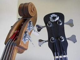
The back story; a rather severely "pulverized” collarbone incident a few years back left me with discomfort when playing my normal 34” scale bass (or my upright, obviously…) for any length of time. Bass isn't my primary instrument, but I've put in a few years as a paid bass player in a few bands and fill in occasionally if the gig seems like a good fit. I discovered the only way to get through an entire gig comfortably was to capo up a few positions on my fretless, and I soon realized a “short scale” bass was going to be necessary if I wanted to continue playing with any level of comfort involved. Hence, this project.
As background, I've only built two electric basses and a couple of EUB's in the past, but I've actively built instruments of various types for many years and maintained an educational website dedicated to musical instrument construction for close to 20 years. I had provided instrument plans and instructional materials for many years but I have since “retired” and dropped my website permanently mid-2016, although some of the free informational material is still available through the Internet Archive Project (Wayback Machine) here:
Bluestem Strings Home
This topic is meant to archive my latest compact bass project start to finish, with the intention of passing along a few of the details of how I build in a relatively small home shop using relatively modest tools. I'm really all about “frugal”, so I think my methodology may be of interest to a few of you who have more modest shops. In some cases I'll show a couple of different ways of doing the same thing to possibly stimulate your “Hey, I can do that...” D.I.Y. gene.
NOTE for 2021: I have since posted a "Short Scale Fretted P Bass Build" that can be found at the following link if that's more to your liking.
Building A Short Scale P Bass
Since I no longer have my own dedicated server space I'm going to do the best I can to do this topic in a way that will keep photos linked to the discussion, and depending on the level of interest I'll have to make a judgment call on how lengthy the entire topic will be and the level of detail that folks might be interested in. I'm not new to doing “photo-logged” topics, so I know the number of photos that might end up here. Still, I'll try to cover as many details as possible without getting overly verbose. I'll try to stick to explanatory text followed by a photo as a convention for my entries. Hopefully there will be some discussion generated during the process that I can participate in. I DO hope it will be a free-for-all discussion; isn't that the whole purpose of the D.I.Y. ethic?
For anyone who might want to try their hand at this design I'll provide the full plan as a pdf, as well as pdfs that can be printed out and tiled to make full size patterns where necessary. When I had my own server space it was no problem to just provide a download link, but for a TalkBass discussion I'll have to figure out a way to do that, so bear with me. I'll include the plans as a direct pdf attachment directly to the discussion, although I may have to do something like a Dropbox link. That will have to wait until I work through all the little things that may or may not pop up that might require changes to the basic drawing so I can distribute it in a complete and tested form.
I'm also doing the posts at a rate that doesn't make it overwhelming for either me or anyone following the topic.
I have a few specific ideas that I want to integrate into this build, so I'll have to do the basic design work with that in mind. Beyond the 30” scale and tape wound strings I'm also working to create as much acoustic energy as possible that will mechanically couple to the bridge transducer to be ultimately amplified. I'm doing this by creating a body from 1/4” thick carved solid wood plates applied to a central body section having a large portion of its center open to create the acoustic chamber. I'm aware that this runs counter to the conventional logic of having a solid central portion from neck to bridge to create maximum sustain, but I'm really going for more of an upright bass tone for this design.
Toward that goal, I'm applying string energy directly to the top by way of the piezo-equipped bridge and picking up some of that body resonance back through the bridge piezo to create the output signal. That's part number one of the formula, the second is having a completely independent magnetic signal available to use as is or to combine with the piezo bridge transducer if that's desirable.
Since the amount of acoustic energy created by the top plate is going to be limited I'm going to have to use a mounting option for the pickup other than attaching its mass directly to the top, which would severely limit its ability to create acoustic energy. I'm going to solve that by attaching the pickup to the back plate and have it extend through an opening in the top plate, basically floating the magnetic pickup.
In any case, I know I'm going to get a perfectly functional bass out of this and the jury will remain out on exactly how well my ideas work out until it is finished and used with an amp. On that front we shall see.
I need something to officially call this and some specifications to work up a plan:
Bluestem 30 Semi-acoustic Fretless Bass
Compact design with 38” overall length and 30” scale length
Walnut body with chambered central layer between carved top and back plates
Top plate features mirrored bass clefs as sound ports
Strings retained by body with recesses to house ball ends
Hip Shot Ultra-light tuners
Ebony headstock overlay with inlaid mother of pearl logo
Walnut neck with two way truss rod
Lined ebony compound radius board with small position markers and side dots
Completely independent pickups with separate 1/4” output jacks
Single magnetic pickup with top mounted volume control
(magnetic pickup used here is a Guitar Fetish MM style because it's in the spare parts box)
L.R. Baggs Element active pre-amp under saddle transducer with top mounted volume control
(under saddle transducer used here is a Baggs Element because it's in the spare parts box)
Recessed Dunlop Strap-loc strap buttons
Black nylon tapewound strings ( LaBella 760N .060”, .070”, .094”, and .115” )
Gator 4G gig bag
Having built “non-standard” designs in the past, I knew it was preferable to obtain a standard type of gig bag prior to finalizing my build parameters to make certain that there would be no difficulty for others to find an inexpensive and appropriately sized high quality gig bag. I also have a local sawyer that I work with, so the walnut I'm using was cut a few years ago from a neighbor's farm and stacked in my storage area for drying. Since I'm “frugal” I chose my stack of walnut to build with.
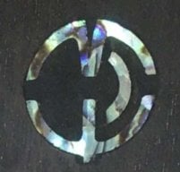
Why “Bluestem” on the headstock? It's a custom logo left over from my days of making custom lap steels. Andy DePaule at Luthiersupply.com supplied me with batches of these and I use one occasionally just so the leftovers don't go to waste. I also get to demonstrate how to add an inlay into the headstock overlay using a unique (and easy) method.
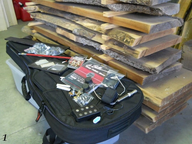
1. The idea is to turn what's shown below into a bass. A bit of research, digging into my spare parts box, and a few orders for stuff I didn't have on hand. Sweetwater for the Gator 4G bag, TubeDepot for the full size high quality 25K pot that will replace the tiny soundhole mount volume control for the Baggs Element under saddle pickup and preamp system that I already had in my spare parts box. Special thanks for answered questions, LaBella Black tape wound strings, and Hipshot tuners goes out to Jason from BassStringsOnline.com. What a guy!
2. Next up was a bit of computer time to draw up the plan with CAD software. I've been using CAD for quite a few years, so it wasn't difficult. The body design started by importing a photo of one of my favorite bass designs, scaling the photo and then tracing a curved line over it for a basic shape. I then modified the body shape it to suit what I wanted in the final design. It's easy to do with CAD, as you simply grab a few points along the body shape and move it to get what you want. The asymmetric headstock design was copied, pasted, and re-sized from a plan for a banjo design I've been recently working with.

Edit: For those wishing access to the final version of the plan shown above, it's available as a PDF attachment in post #77.
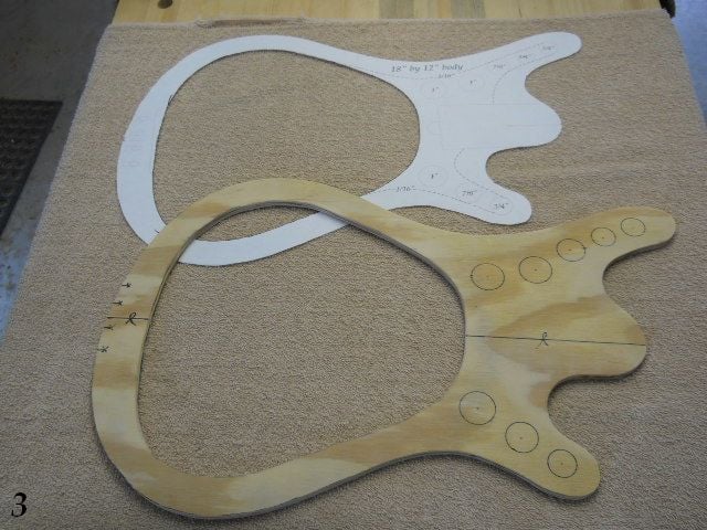
3. I converted the body portion of the drawing into 4 pdfs (I'll supply them here later, of course) that could be printed and assembled into a full size body shape template. This was traced on some scrap plywood to make the full size template. It is also used to hold the arched body for some of the work. The full drawing has the body superimposed over a 18” by 12” grid if someone would want to reproduce the body shape “old school”.
I'll post more as time permits!
Do jump in and let me know if there's any interest.
As background, I've only built two electric basses and a couple of EUB's in the past, but I've actively built instruments of various types for many years and maintained an educational website dedicated to musical instrument construction for close to 20 years. I had provided instrument plans and instructional materials for many years but I have since “retired” and dropped my website permanently mid-2016, although some of the free informational material is still available through the Internet Archive Project (Wayback Machine) here:
Bluestem Strings Home
This topic is meant to archive my latest compact bass project start to finish, with the intention of passing along a few of the details of how I build in a relatively small home shop using relatively modest tools. I'm really all about “frugal”, so I think my methodology may be of interest to a few of you who have more modest shops. In some cases I'll show a couple of different ways of doing the same thing to possibly stimulate your “Hey, I can do that...” D.I.Y. gene.
NOTE for 2021: I have since posted a "Short Scale Fretted P Bass Build" that can be found at the following link if that's more to your liking.
Building A Short Scale P Bass
Since I no longer have my own dedicated server space I'm going to do the best I can to do this topic in a way that will keep photos linked to the discussion, and depending on the level of interest I'll have to make a judgment call on how lengthy the entire topic will be and the level of detail that folks might be interested in. I'm not new to doing “photo-logged” topics, so I know the number of photos that might end up here. Still, I'll try to cover as many details as possible without getting overly verbose. I'll try to stick to explanatory text followed by a photo as a convention for my entries. Hopefully there will be some discussion generated during the process that I can participate in. I DO hope it will be a free-for-all discussion; isn't that the whole purpose of the D.I.Y. ethic?
For anyone who might want to try their hand at this design I'll provide the full plan as a pdf, as well as pdfs that can be printed out and tiled to make full size patterns where necessary. When I had my own server space it was no problem to just provide a download link, but for a TalkBass discussion I'll have to figure out a way to do that, so bear with me. I'll include the plans as a direct pdf attachment directly to the discussion, although I may have to do something like a Dropbox link. That will have to wait until I work through all the little things that may or may not pop up that might require changes to the basic drawing so I can distribute it in a complete and tested form.
I'm also doing the posts at a rate that doesn't make it overwhelming for either me or anyone following the topic.
I have a few specific ideas that I want to integrate into this build, so I'll have to do the basic design work with that in mind. Beyond the 30” scale and tape wound strings I'm also working to create as much acoustic energy as possible that will mechanically couple to the bridge transducer to be ultimately amplified. I'm doing this by creating a body from 1/4” thick carved solid wood plates applied to a central body section having a large portion of its center open to create the acoustic chamber. I'm aware that this runs counter to the conventional logic of having a solid central portion from neck to bridge to create maximum sustain, but I'm really going for more of an upright bass tone for this design.
Toward that goal, I'm applying string energy directly to the top by way of the piezo-equipped bridge and picking up some of that body resonance back through the bridge piezo to create the output signal. That's part number one of the formula, the second is having a completely independent magnetic signal available to use as is or to combine with the piezo bridge transducer if that's desirable.
Since the amount of acoustic energy created by the top plate is going to be limited I'm going to have to use a mounting option for the pickup other than attaching its mass directly to the top, which would severely limit its ability to create acoustic energy. I'm going to solve that by attaching the pickup to the back plate and have it extend through an opening in the top plate, basically floating the magnetic pickup.
In any case, I know I'm going to get a perfectly functional bass out of this and the jury will remain out on exactly how well my ideas work out until it is finished and used with an amp. On that front we shall see.
I need something to officially call this and some specifications to work up a plan:
Bluestem 30 Semi-acoustic Fretless Bass
Compact design with 38” overall length and 30” scale length
Walnut body with chambered central layer between carved top and back plates
Top plate features mirrored bass clefs as sound ports
Strings retained by body with recesses to house ball ends
Hip Shot Ultra-light tuners
Ebony headstock overlay with inlaid mother of pearl logo
Walnut neck with two way truss rod
Lined ebony compound radius board with small position markers and side dots
Completely independent pickups with separate 1/4” output jacks
Single magnetic pickup with top mounted volume control
(magnetic pickup used here is a Guitar Fetish MM style because it's in the spare parts box)
L.R. Baggs Element active pre-amp under saddle transducer with top mounted volume control
(under saddle transducer used here is a Baggs Element because it's in the spare parts box)
Recessed Dunlop Strap-loc strap buttons
Black nylon tapewound strings ( LaBella 760N .060”, .070”, .094”, and .115” )
Gator 4G gig bag
Having built “non-standard” designs in the past, I knew it was preferable to obtain a standard type of gig bag prior to finalizing my build parameters to make certain that there would be no difficulty for others to find an inexpensive and appropriately sized high quality gig bag. I also have a local sawyer that I work with, so the walnut I'm using was cut a few years ago from a neighbor's farm and stacked in my storage area for drying. Since I'm “frugal” I chose my stack of walnut to build with.
Why “Bluestem” on the headstock? It's a custom logo left over from my days of making custom lap steels. Andy DePaule at Luthiersupply.com supplied me with batches of these and I use one occasionally just so the leftovers don't go to waste. I also get to demonstrate how to add an inlay into the headstock overlay using a unique (and easy) method.
1. The idea is to turn what's shown below into a bass. A bit of research, digging into my spare parts box, and a few orders for stuff I didn't have on hand. Sweetwater for the Gator 4G bag, TubeDepot for the full size high quality 25K pot that will replace the tiny soundhole mount volume control for the Baggs Element under saddle pickup and preamp system that I already had in my spare parts box. Special thanks for answered questions, LaBella Black tape wound strings, and Hipshot tuners goes out to Jason from BassStringsOnline.com. What a guy!
2. Next up was a bit of computer time to draw up the plan with CAD software. I've been using CAD for quite a few years, so it wasn't difficult. The body design started by importing a photo of one of my favorite bass designs, scaling the photo and then tracing a curved line over it for a basic shape. I then modified the body shape it to suit what I wanted in the final design. It's easy to do with CAD, as you simply grab a few points along the body shape and move it to get what you want. The asymmetric headstock design was copied, pasted, and re-sized from a plan for a banjo design I've been recently working with.
Edit: For those wishing access to the final version of the plan shown above, it's available as a PDF attachment in post #77.
3. I converted the body portion of the drawing into 4 pdfs (I'll supply them here later, of course) that could be printed and assembled into a full size body shape template. This was traced on some scrap plywood to make the full size template. It is also used to hold the arched body for some of the work. The full drawing has the body superimposed over a 18” by 12” grid if someone would want to reproduce the body shape “old school”.
I'll post more as time permits!
Do jump in and let me know if there's any interest.
Last edited: