Enjoy the benefits of a premium membership!
Upgrade Account
-
TalkBass has been independent since 1998. Add your voice.
Create a free account to reply to discussions, view embedded media, and browse with fewer display ads.
Join free Log in
Want zero display ads or expanded classifieds tools? Compare plans.
You are using an out of date browser. It may not display this or other websites correctly.
You should upgrade or use an alternative browser.
You should upgrade or use an alternative browser.
More options
Who Replied?
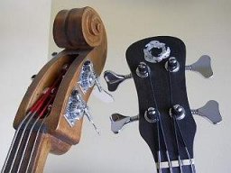
Thank you, BritFunk. I think it's coming along smashingly!VERY interested to watch the progression of this build. Subbed.



Thanks, I appreciate the input. There's been so little comment I was a bit concerned that it really wasn't worth putting the effort into doing, or perhaps the level of detail was more than folks really want to see. If nobody cares there's not much point, but I am committed to doing the whole topic!
I agree with the consensus, please keep the updates coming! Love the idea and detail. I'm still in the planing phase of a similar project and this is helping out tons, especially because I've never made a hollow/semi-hollow/carved top body. Thank you, and so far it is looking absolutely beautiful!
Thanks much. We'll keep 'em coming, and the best of luck on your new project!I agree with the consensus, please keep the updates coming! Love the idea and detail. I'm still in the planing phase of a similar project and this is helping out tons, especially because I've never made a hollow/semi-hollow/carved top body. Thank you, and so far it is looking absolutely beautiful!
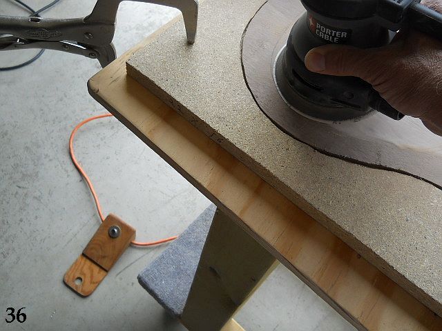
36. I often use an extension cord that has a momentary foot switch fitted at the end. This allows ultra-fine control of the sander by tapping the switch with the foot to “pulse” the sander for detail work.
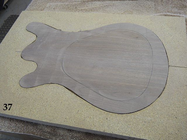
37. Here the top plate inner contour has been shaped and sanded and is ready to be joined to the body's central section.
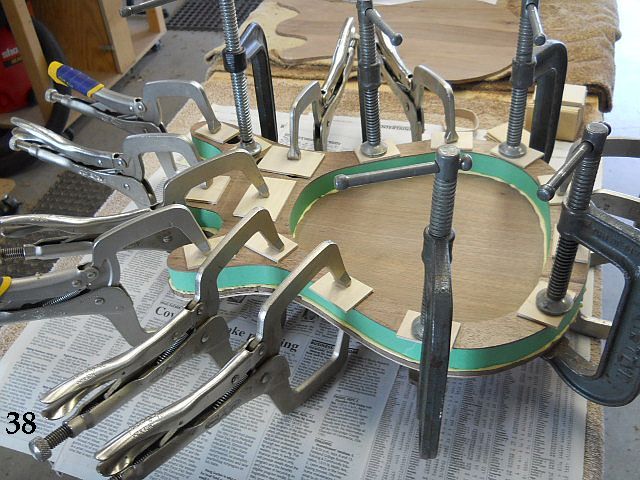
38. Mating surfaces have Titebond Original applied and the top is clamped against the central section of the body. The template is used under the plate to cushion the force of the clamps and prevent marring of the top plate. The Vise Grip quick clamps are handy; I purchase them when I see a half price sale to reduce the expense in adding to my collection.
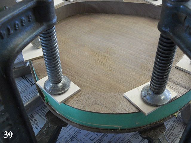
39. Glue squeeze out is removed. The remaining excess glue will come off when the tape is peeled away.
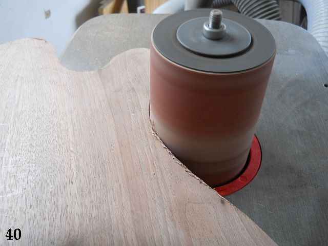
40. The overhang is removed with the vertical oscillating spindle sander. I normally would use a bearing guided router bit, but there's enough work already put into the top plate that I'm sanding to demonstrate how to reduce the possibility of chip out.
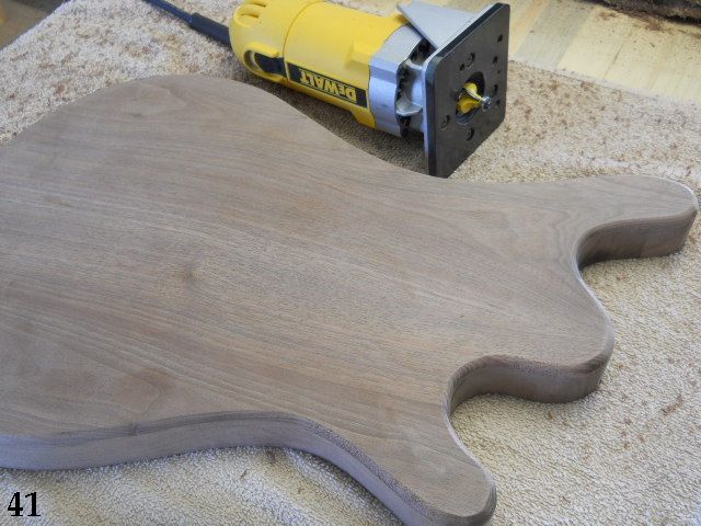
41. The edge is rounded over with 1/4” radius bearing guided router bit. The trim router base is small enough that it isn't angled enough to matter by the arching of the top. The round over was done in two passes, the first using a climb cut (to minimize the possibility of chip out) and the second going counter-clockwise around the body edge. To greatly reduce the possibility of chip out it is always preferred to use the “standard” method of a combination of climb and standard cut directions based on the grain direction of the top plate. I didn't strictly follow this sage advice because the top plate in this case is composed of flat grain and it was already sanded flush to the edge. If the wood would have been quarter sawn I would have gone the climb / standard cut route.
Since this is a new design for me I'm going to shift gears a bit and go to the neck; the reason being that I want to do the actual neck mounting so the EXACT position of the remaining components for the top can be adjusted by where the string paths end up. If I do the neck pocket prior to doing the rest of the layout for the body it doesn't matter if the alignment ends up being a tiny bit off, the position of things like the magnetic pickup opening and the string ferrule locations can be slightly adjusted. I'm all about easy… and not turning a lot of effort into scrap!
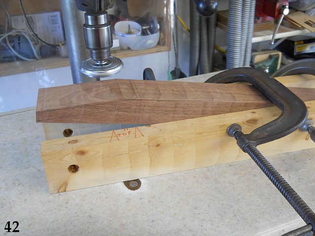
42. Another section of tree was used to make a 28” by 3” wide by 1-3/4” thick block to use for the neck. The headstock area could have been spliced if thinner wood was going to be used, but since this was available to me I went with the thicker neck blank.
43. The top area of the headstock was band sawn off and the Safe-T-Planer is being used to true up the face and mate the rear edge of the angle to the line that indicates the headstock side of the nut.

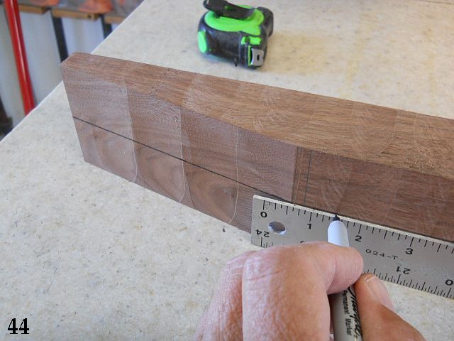
44. Since the blank is 3” wide and one of my rulers is 1-1/2” wide I'm using it to draw a line down the center of the blank.
Stay tuned...
37. Here the top plate inner contour has been shaped and sanded and is ready to be joined to the body's central section.
38. Mating surfaces have Titebond Original applied and the top is clamped against the central section of the body. The template is used under the plate to cushion the force of the clamps and prevent marring of the top plate. The Vise Grip quick clamps are handy; I purchase them when I see a half price sale to reduce the expense in adding to my collection.
39. Glue squeeze out is removed. The remaining excess glue will come off when the tape is peeled away.
40. The overhang is removed with the vertical oscillating spindle sander. I normally would use a bearing guided router bit, but there's enough work already put into the top plate that I'm sanding to demonstrate how to reduce the possibility of chip out.
41. The edge is rounded over with 1/4” radius bearing guided router bit. The trim router base is small enough that it isn't angled enough to matter by the arching of the top. The round over was done in two passes, the first using a climb cut (to minimize the possibility of chip out) and the second going counter-clockwise around the body edge. To greatly reduce the possibility of chip out it is always preferred to use the “standard” method of a combination of climb and standard cut directions based on the grain direction of the top plate. I didn't strictly follow this sage advice because the top plate in this case is composed of flat grain and it was already sanded flush to the edge. If the wood would have been quarter sawn I would have gone the climb / standard cut route.
Since this is a new design for me I'm going to shift gears a bit and go to the neck; the reason being that I want to do the actual neck mounting so the EXACT position of the remaining components for the top can be adjusted by where the string paths end up. If I do the neck pocket prior to doing the rest of the layout for the body it doesn't matter if the alignment ends up being a tiny bit off, the position of things like the magnetic pickup opening and the string ferrule locations can be slightly adjusted. I'm all about easy… and not turning a lot of effort into scrap!
42. Another section of tree was used to make a 28” by 3” wide by 1-3/4” thick block to use for the neck. The headstock area could have been spliced if thinner wood was going to be used, but since this was available to me I went with the thicker neck blank.
43. The top area of the headstock was band sawn off and the Safe-T-Planer is being used to true up the face and mate the rear edge of the angle to the line that indicates the headstock side of the nut.
44. Since the blank is 3” wide and one of my rulers is 1-1/2” wide I'm using it to draw a line down the center of the blank.
Stay tuned...

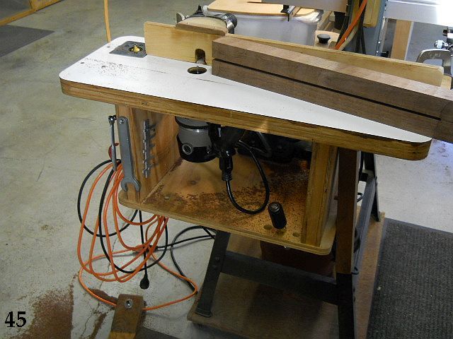
45. The truss rod channel is routed slightly deeper than the two way rod depth. I want to be able to pull the rod out from the heel end if there's ever a need to do that.
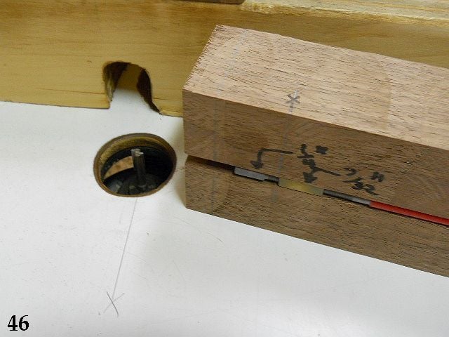
46. The two way rod I have from Stewart-MacDonald has an Allen head adjustment screw that's slightly larger than the 7/32” width of the recommended channel size. I pulled the 7/32” router bit and swapped it for a 1/4” bit to make the channel a bit wider and deeper to accommodate the Stu-Mac adjusting screw. This also makes it easier to pull the rod length-wise from the truss rod channel should it ever become necessary to do so. The channel area above the adjustment screw could be fitted with a small section of wood filler strip to prevent the rod from moving lengthwise if desired, although I don't find it necessary to do that. Rod shown “upside down” to demonstrate checking the channel width necessary for the extra width of the rod screw.
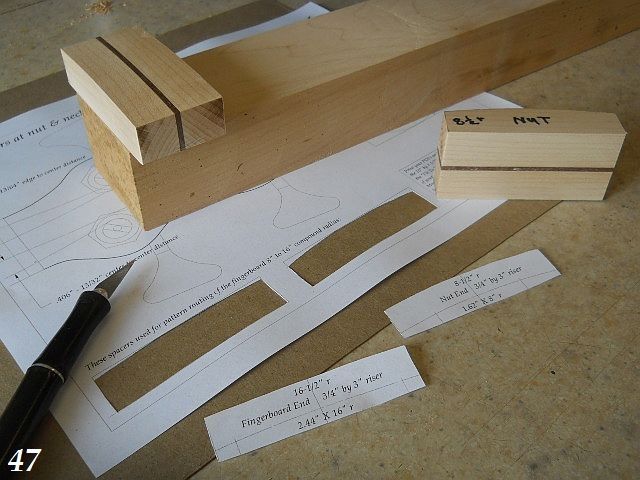
47. These patterns for radius jig guides are cut out from the full size “Neck Templates” pdf print and used to make identical wood guides to add to a strong and straight piece of hardwood that will hold the fingerboard blank. It will become clear how these guides work in later photos, but they basically space the fingerboard above the carbide router bit and the compound radius is formed by passing the entire jig over the bit and rocking it as it is held against the router table. It's safe to do this if you use a bit of common sense; the router bit only removing the small bit of excess material to create the arched top surface of the fingerboard. You can cut virtually any dimension of single or compound radius board by making a new set of guides. It's easier to show than to explain...
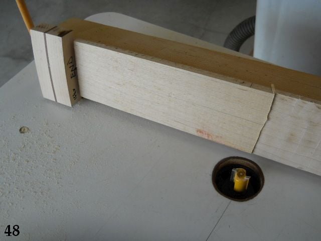
48. Since this is a new guide I made a test piece the same size as my fingerboard blank to check the actual results before committing my ebony fingerboard blank.
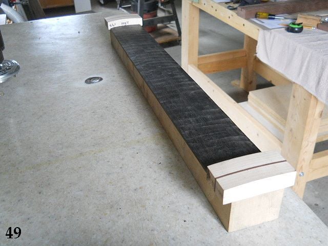
49. The guide next produced a very accurate and true ebony compound radius fingerboard. It will be cut to the proper taper and width after sanding to remove the lines left behind from the 5/8” diameter router bit. The radiused fingerboard is sanded to remove the slight imperfections left from routing. I'll show my sanding block a bit further along.
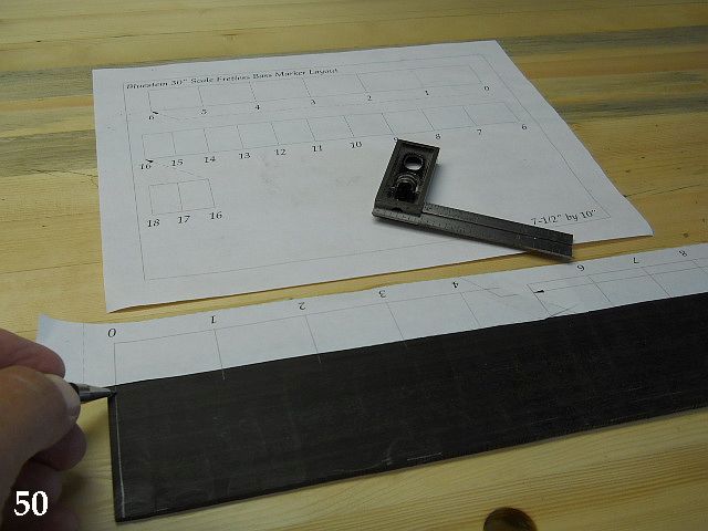
50. A template for marking out the fingerboard line positions is made by carefully mating the sections cut from the full size printed pdf guide. (I'll supply those pdfs and others later after the build is complete for anyone who wants them.) Do check the zero to 12th to verify the 15” distance (half the scale length) is correct, but there should be no problem if the printed size is correct.
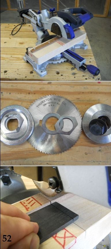
51. The untrimmed fingerboard has fret slots cut so filler material can be added to make the lined fingerboard. Here's my "specialty" slotting saw, details to follow in step #52.
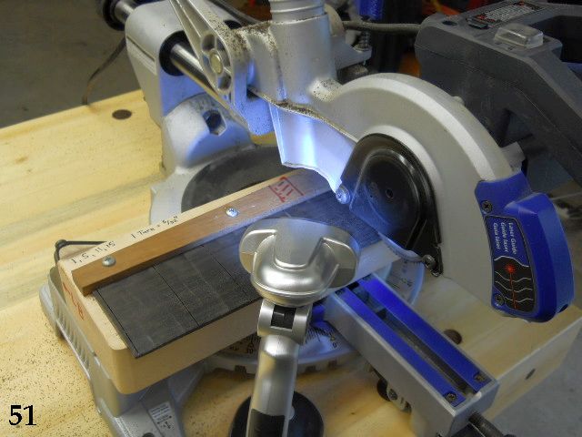
52. I often get questions about my fret slotting setup. My saw is based on an inexpensive Kobalt sliding miter saw from Lowe's, sale priced under $100. A small special purpose slotting blade was purchased for around $10 from McMaster-Carr (Thurston Manufacturing Company #J-034 .023” wide by 2-3/4” diameter 1” arbor 72 teeth screw slotting blade McMaster-Carr #3062A31) and adapted to the saw using a reducing bushing and spacers fitted between the saw arbor flanges as shown. The saw has a simple adjustable depth stop; it works in conjunction with the maple bed so slot depth can be easily set. The board is left full width and the taper cut after slotting. The slot positions are marked directly on the board and the marked lines simply aligned to the cut in the rear fence. Easy-peasey! It has cut hundreds of letter-perfect slots requiring no tedious hand sawing, and I find it highly beneficial to be able to see the slots being cut. Over many years of slotting fretboards this is by far the best setup I've ever used. It's fairly compact and stores on an overhead shelf when it isn't being used.
46. The two way rod I have from Stewart-MacDonald has an Allen head adjustment screw that's slightly larger than the 7/32” width of the recommended channel size. I pulled the 7/32” router bit and swapped it for a 1/4” bit to make the channel a bit wider and deeper to accommodate the Stu-Mac adjusting screw. This also makes it easier to pull the rod length-wise from the truss rod channel should it ever become necessary to do so. The channel area above the adjustment screw could be fitted with a small section of wood filler strip to prevent the rod from moving lengthwise if desired, although I don't find it necessary to do that. Rod shown “upside down” to demonstrate checking the channel width necessary for the extra width of the rod screw.
47. These patterns for radius jig guides are cut out from the full size “Neck Templates” pdf print and used to make identical wood guides to add to a strong and straight piece of hardwood that will hold the fingerboard blank. It will become clear how these guides work in later photos, but they basically space the fingerboard above the carbide router bit and the compound radius is formed by passing the entire jig over the bit and rocking it as it is held against the router table. It's safe to do this if you use a bit of common sense; the router bit only removing the small bit of excess material to create the arched top surface of the fingerboard. You can cut virtually any dimension of single or compound radius board by making a new set of guides. It's easier to show than to explain...
48. Since this is a new guide I made a test piece the same size as my fingerboard blank to check the actual results before committing my ebony fingerboard blank.
49. The guide next produced a very accurate and true ebony compound radius fingerboard. It will be cut to the proper taper and width after sanding to remove the lines left behind from the 5/8” diameter router bit. The radiused fingerboard is sanded to remove the slight imperfections left from routing. I'll show my sanding block a bit further along.
50. A template for marking out the fingerboard line positions is made by carefully mating the sections cut from the full size printed pdf guide. (I'll supply those pdfs and others later after the build is complete for anyone who wants them.) Do check the zero to 12th to verify the 15” distance (half the scale length) is correct, but there should be no problem if the printed size is correct.
51. The untrimmed fingerboard has fret slots cut so filler material can be added to make the lined fingerboard. Here's my "specialty" slotting saw, details to follow in step #52.
52. I often get questions about my fret slotting setup. My saw is based on an inexpensive Kobalt sliding miter saw from Lowe's, sale priced under $100. A small special purpose slotting blade was purchased for around $10 from McMaster-Carr (Thurston Manufacturing Company #J-034 .023” wide by 2-3/4” diameter 1” arbor 72 teeth screw slotting blade McMaster-Carr #3062A31) and adapted to the saw using a reducing bushing and spacers fitted between the saw arbor flanges as shown. The saw has a simple adjustable depth stop; it works in conjunction with the maple bed so slot depth can be easily set. The board is left full width and the taper cut after slotting. The slot positions are marked directly on the board and the marked lines simply aligned to the cut in the rear fence. Easy-peasey! It has cut hundreds of letter-perfect slots requiring no tedious hand sawing, and I find it highly beneficial to be able to see the slots being cut. Over many years of slotting fretboards this is by far the best setup I've ever used. It's fairly compact and stores on an overhead shelf when it isn't being used.
Last edited:
53. Filler strips were cut from a contrasting wood material, in this case mahogany. I didn't want an overly-bright line like what would have resulted from maple being used. See steps #24-#26 to see how the filler strips are made. A small dispensing bottle is used to insert a generous amount of Original Titebond directly in the slot. These bottles are available from specialty suppliers; this one was purchased at a store carrying Rockler brand materials. Insert the filler strip to the bottom of the slot and clean up the excess glue with a slightly moistened paper towel.

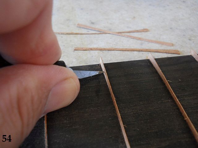
54. A #11 Exacto blade is used to lightly score the filler material and the excess is snapped off.
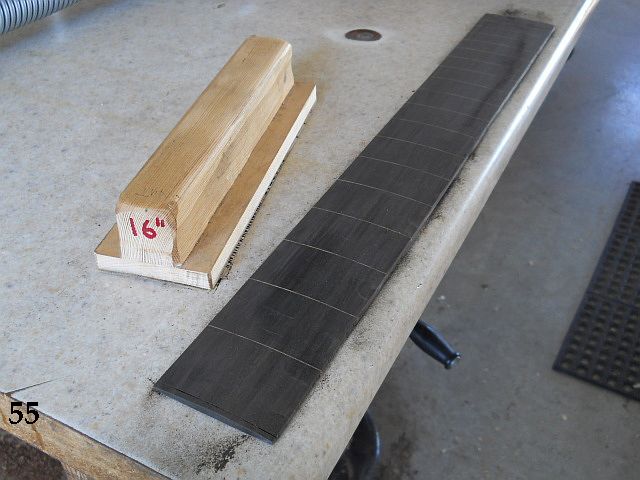
55. A radius block with sandpaper is used to level the filler strips to the compound radius board. Make sure your radius block is at least as large as the radius at the large end of the fingerboard; 16” radius in my case. My radius blocks are made by drawing the proper outline on the end of a section of maple board and passing it obliquely over a 10” carbide blade on the table saw, taking about 1/16" at a time for each pass. It takes a few passes to mate the shape fairly close and it's finished up with a curved cabinet scraper blade. Do take a bit of extra effort to attach a nice handle on top! The radius block can be tilted to sand the more convex areas, taking care not to flatten the crown of the board. Since I'm sanding areas that have some marks left from forming the top curvature with a router bit it's easy to monitor the progress along the marks left over from the process. For reasons I won't elaborate on here I'll also suggest that as you sand to remove the rough carving marks that you concentrate your sanding strokes along imaginary lines that follow the actual string paths of each of the four strings. That means your sanding strokes will fan out a bit as you go toward the heel end of the board. Everything will blend together, but this will make for a better-playing action when you are finished.
If you opt to add position markers on the face of the fingerboard now is a good time to do so. I chose to add 5/32” Abalone dots purely because I like the way they dress up the otherwise plain surface. The board is held to a flat work surface with a strip of double-stick tape as it is sanded.
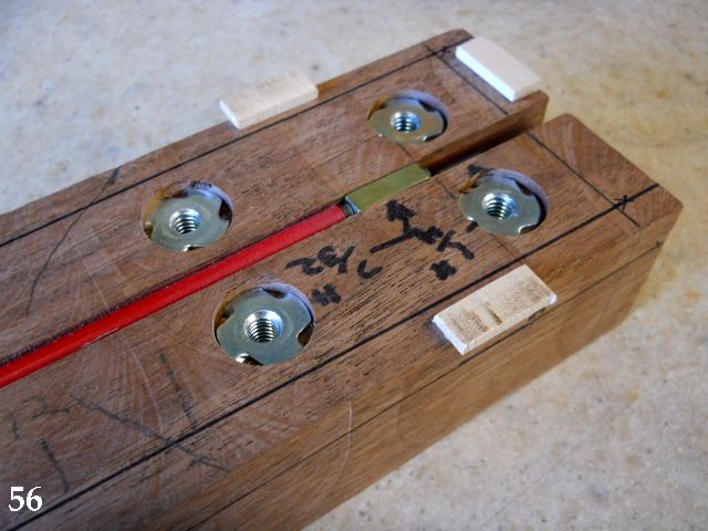
56. Lots of stuff going on in this photo! The actual fingerboard shape is outlined on the neck blank. Small blocks are added (with the fingerboard in position) to make sure the fingerboard is glued exactly where it is supposed to be. Long shank (9/16”) 1/4” by 20 tee nuts are installed to mount the neck. DO NOT forget to do this BEFORE you glue the fingerboard on! I cut 3/8” squares of masking tape and affix them over the tee nut tapped holes so glue has no possibility of entering the threaded area. Standard directions for Stewart MacDonald two way truss rod installation are followed when gluing the board on. (3/4” tape over the slot, use trowel to apply glue uniformly, peel off tape and add board).
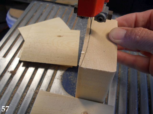
57. Five pieces of scrap 2” x 4” have a radius surface cut to use as clamping cauls over 1/4” cork.
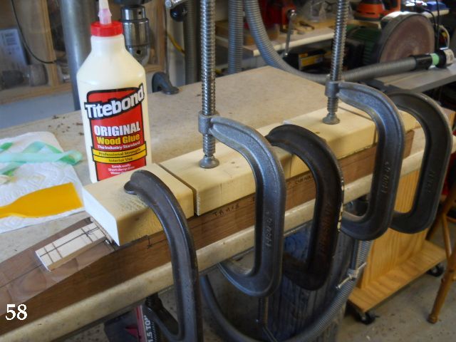
58. The fingerboard is glued and clamped with 1/4” cork between the curved cauls and the fingerboard.
Gotta go for now...
54. A #11 Exacto blade is used to lightly score the filler material and the excess is snapped off.
55. A radius block with sandpaper is used to level the filler strips to the compound radius board. Make sure your radius block is at least as large as the radius at the large end of the fingerboard; 16” radius in my case. My radius blocks are made by drawing the proper outline on the end of a section of maple board and passing it obliquely over a 10” carbide blade on the table saw, taking about 1/16" at a time for each pass. It takes a few passes to mate the shape fairly close and it's finished up with a curved cabinet scraper blade. Do take a bit of extra effort to attach a nice handle on top! The radius block can be tilted to sand the more convex areas, taking care not to flatten the crown of the board. Since I'm sanding areas that have some marks left from forming the top curvature with a router bit it's easy to monitor the progress along the marks left over from the process. For reasons I won't elaborate on here I'll also suggest that as you sand to remove the rough carving marks that you concentrate your sanding strokes along imaginary lines that follow the actual string paths of each of the four strings. That means your sanding strokes will fan out a bit as you go toward the heel end of the board. Everything will blend together, but this will make for a better-playing action when you are finished.
If you opt to add position markers on the face of the fingerboard now is a good time to do so. I chose to add 5/32” Abalone dots purely because I like the way they dress up the otherwise plain surface. The board is held to a flat work surface with a strip of double-stick tape as it is sanded.
56. Lots of stuff going on in this photo! The actual fingerboard shape is outlined on the neck blank. Small blocks are added (with the fingerboard in position) to make sure the fingerboard is glued exactly where it is supposed to be. Long shank (9/16”) 1/4” by 20 tee nuts are installed to mount the neck. DO NOT forget to do this BEFORE you glue the fingerboard on! I cut 3/8” squares of masking tape and affix them over the tee nut tapped holes so glue has no possibility of entering the threaded area. Standard directions for Stewart MacDonald two way truss rod installation are followed when gluing the board on. (3/4” tape over the slot, use trowel to apply glue uniformly, peel off tape and add board).
57. Five pieces of scrap 2” x 4” have a radius surface cut to use as clamping cauls over 1/4” cork.
58. The fingerboard is glued and clamped with 1/4” cork between the curved cauls and the fingerboard.
Gotta go for now...
Last edited:

Nice work @rudy4444 glad you decided to contribute to this forum, its most welcome. Please keep it up!

Of all the cool stuff you are posting here, I just gotta ask about those glue bottles/tops. Do have a link to them or other info? Not sure what to Google to find it. Do you have to thin the Titebond?
Beej & ponticat, thanks much for the vote of confidence. As I stated before, I don't do a lot of basses, but I thought it would be a great way of contributing to Talkbass. All these build topics have great information in them. I learn things from perusing the topics and hopefully someone else will pick up something from this topic.
It's one of my "essential" fretting tools. I use Original Titebond and do not dilute it. When I'm done with the job I clean it out with warm water and a Q-tip and let it air dry. The metal tip doesn't quite fit into a .023" slot, but it's easy to lay a bead of glue down and let it sink into the slot. My local woodworking store has these on hand, but it's a Rockler product. Here it is:Of all the cool stuff you are posting here, I just gotta ask about those glue bottles/tops. Do have a link to them or other info? Not sure what to Google to find it. Do you have to thin the Titebond?
Invalid Link Removed

Of all the cool stuff you are posting here, I just gotta ask about those glue bottles/tops. Do have a link to them or other info? Not sure what to Google to find it. Do you have to thin the Titebond?
If you can get past the "people who don't know any better freak out" factor, glue applicator syringes and needles are a common item from the fiber optic industry (at least.) Standard F.O. glue needle is 0.9mm OD. Unlike hypodermics, the needle is blunt, (and probably kinda large) but otherwise they are basically the same, and would serve the same purpose here, I suspect. I still have most of a bag of 50, but I needed at least a dozen for a fiber job - and two 10 packs was more than a 50-pack, as far as I recall. With fiber epoxy you can't wash them out and reuse them like you can with wood glue. Less total glue volume between refills than the Rockler bottle, but that probably would not be a huge factor for this job.
To see what those are, look here, though I doubt you'd want to buy from there if I recall the minimum per-order $ amount correctly. Empty Epoxy Syringe 5 Pack - Fiber Instrument Sales
Last edited:

I'm thoroughly enjoying this thread, as well. Please do keep posting!Thanks, I appreciate the input. There's been so little comment I was a bit concerned that it really wasn't worth putting the effort into doing, or perhaps the level of detail was more than folks really want to see. If nobody cares there's not much point, but I am committed to doing the whole topic!
Will do, GKon. Mucho Gracias!I'm thoroughly enjoying this thread, as well. Please do keep posting!
59. Since the neck sides are still square at this point I use a pair of outriggers to keep the neck blank from rocking on the curved fingerboard face and plane the end of the neck that will be joined to the neck pocket.
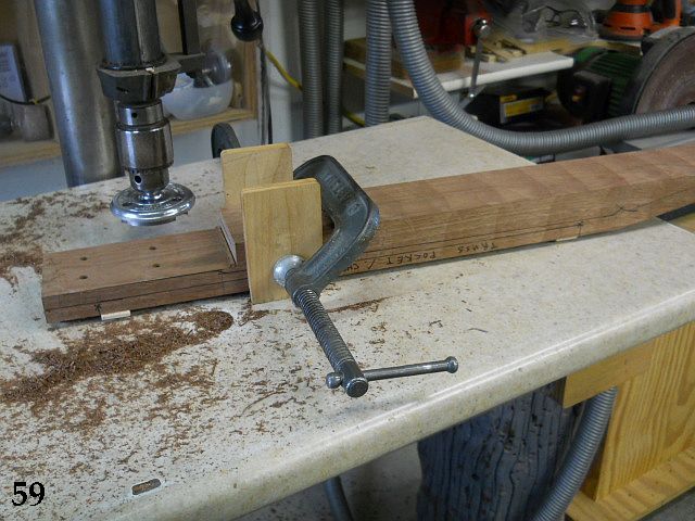
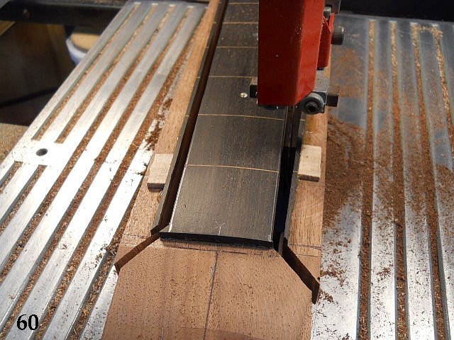
60. The fingerboard top profile is marked and excess material cut away at each side.
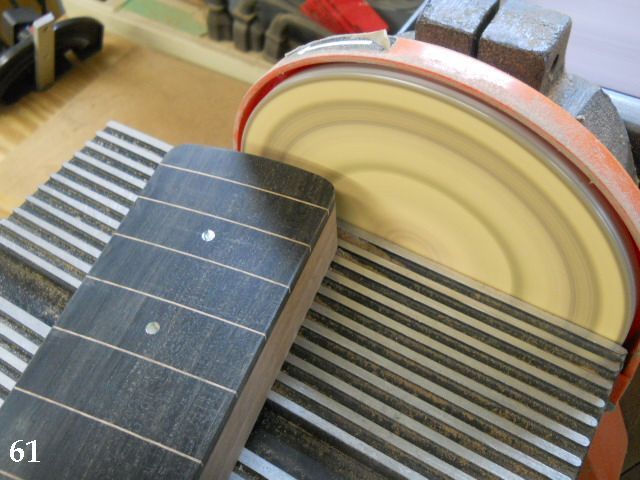
61. Both long sides and the neck end are sanded to their finished profile. The end of the neck is shaped for a Strat-style neck pocket. The 16” end radius is traced from the fingerboard profile cut from the “Neck Templates” pdf (see step #47). The corners are radiused to 1/4” to match the template router bit 1/2” diameter.
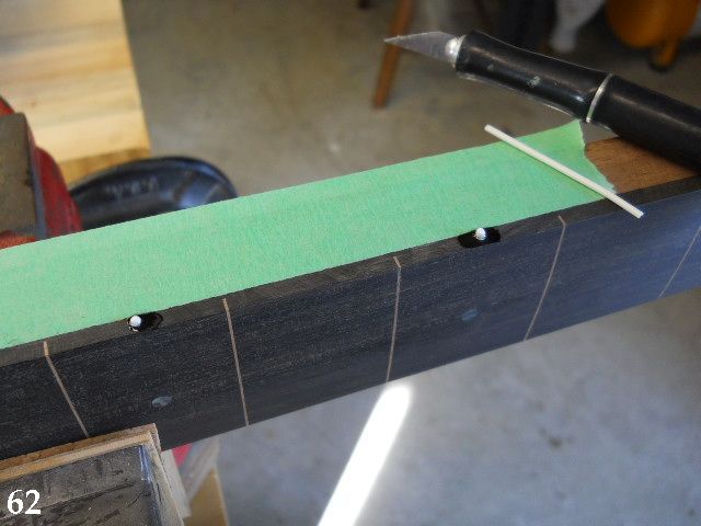
62. This was a good time to add the 1/16” position dots at the side of the board. A drop of superglue is added to the holes (drilled 1/4” deep) before the rod is inserted and cut off with the Exacto knife. They are sanded level after the glue has completely dried.
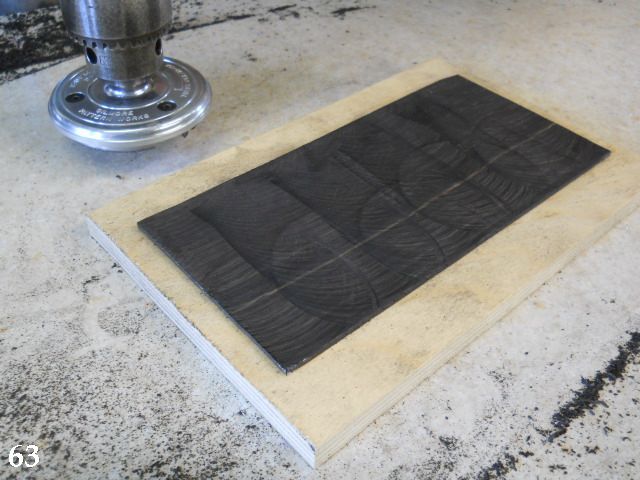
63. The headstock overlay is leveled and sanded (both sides) by attaching it to a backing board with double-sided tape.
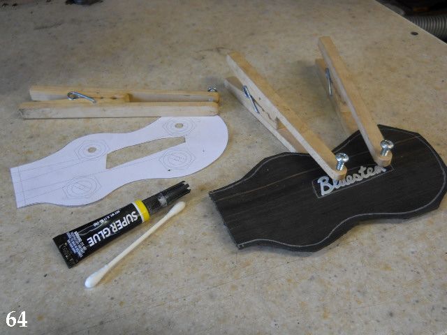
64. The headstock shape it traced and the pearl logo is clamped in position, making sure it won't be covered by any of the tuner hardware. A bead of thin superglue is wicked around the outside edges and any extra removed with a Q-tip.
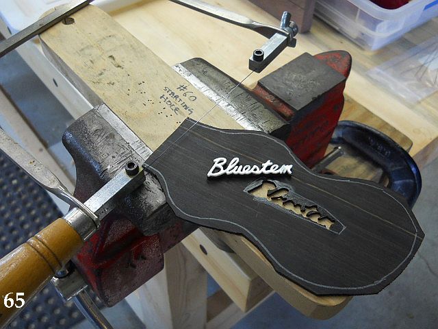
65. The logo is carefully cut out after drilling a few #60 starter holes to insert the blade through.
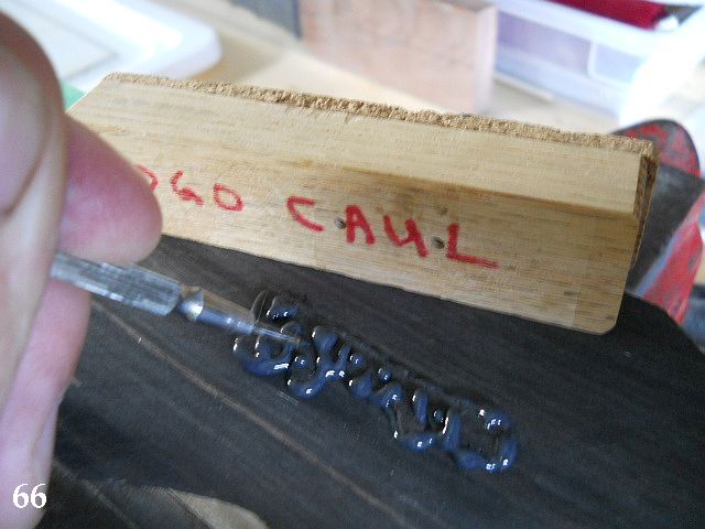
66. The front of the headstock has tape stretched across the inlay cutout and the inlay is inserted from the rear after the cavity is filled with black 3 hour epoxy. It is clamped down with a 1/4” cork padded caul so the front surface of the inlay will be exactly level with the overlay front surface.
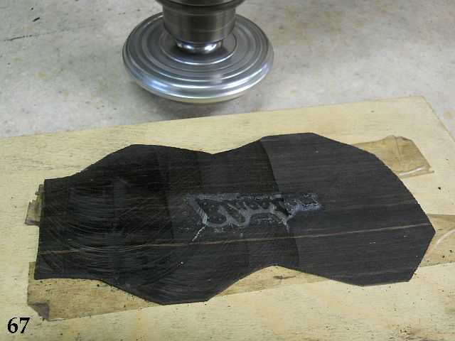
67. The rear face is planed lightly to removed the protruding portion of the ebony attached to the rear of the pearl inlay. After sanding it's difficult to see the inlay from the rear.
68. Finished overlay ready to add to the neck. Inlay doesn't get much better than this, and it's super easy!
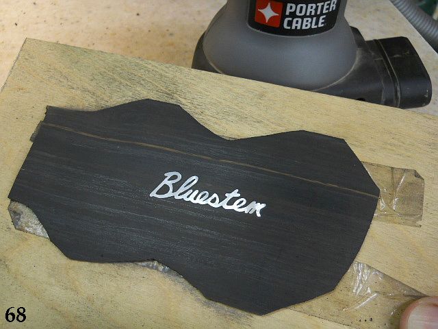
Hope you enjoyed this installment. More to come as we progress toward the finish line!
60. The fingerboard top profile is marked and excess material cut away at each side.
61. Both long sides and the neck end are sanded to their finished profile. The end of the neck is shaped for a Strat-style neck pocket. The 16” end radius is traced from the fingerboard profile cut from the “Neck Templates” pdf (see step #47). The corners are radiused to 1/4” to match the template router bit 1/2” diameter.
62. This was a good time to add the 1/16” position dots at the side of the board. A drop of superglue is added to the holes (drilled 1/4” deep) before the rod is inserted and cut off with the Exacto knife. They are sanded level after the glue has completely dried.
63. The headstock overlay is leveled and sanded (both sides) by attaching it to a backing board with double-sided tape.
64. The headstock shape it traced and the pearl logo is clamped in position, making sure it won't be covered by any of the tuner hardware. A bead of thin superglue is wicked around the outside edges and any extra removed with a Q-tip.
65. The logo is carefully cut out after drilling a few #60 starter holes to insert the blade through.
66. The front of the headstock has tape stretched across the inlay cutout and the inlay is inserted from the rear after the cavity is filled with black 3 hour epoxy. It is clamped down with a 1/4” cork padded caul so the front surface of the inlay will be exactly level with the overlay front surface.
67. The rear face is planed lightly to removed the protruding portion of the ebony attached to the rear of the pearl inlay. After sanding it's difficult to see the inlay from the rear.
68. Finished overlay ready to add to the neck. Inlay doesn't get much better than this, and it's super easy!
Hope you enjoyed this installment. More to come as we progress toward the finish line!

69. The neck is used to mark out three pieces of Baltic Birch plywood that will be used to make the neck pocket routing jig. The curved portion is sanded to match the neck heel end and the two sides have the edges sanded flat. The pieces are butted against the neck and glued to another piece of plywood that serves as the base.
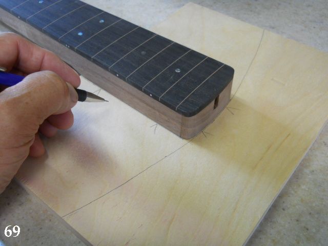
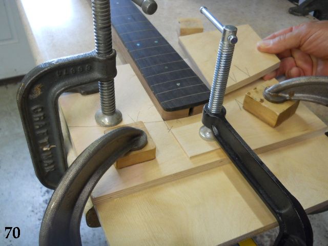
70. Here two of the sections have been glued and clamped with the third section being added. Once dry, the base layer is cut out and a bearing guided carbide router bit is used to pattern route the base layer to create the neck pocket routing jig.
71. A short section of wood a bit larger than the neck has the neck bolt locations transferred to the surface by inserting short sections of 1/4” - 20 all thread and “denting” the wood below.
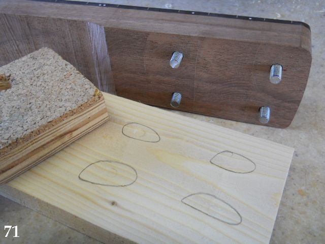
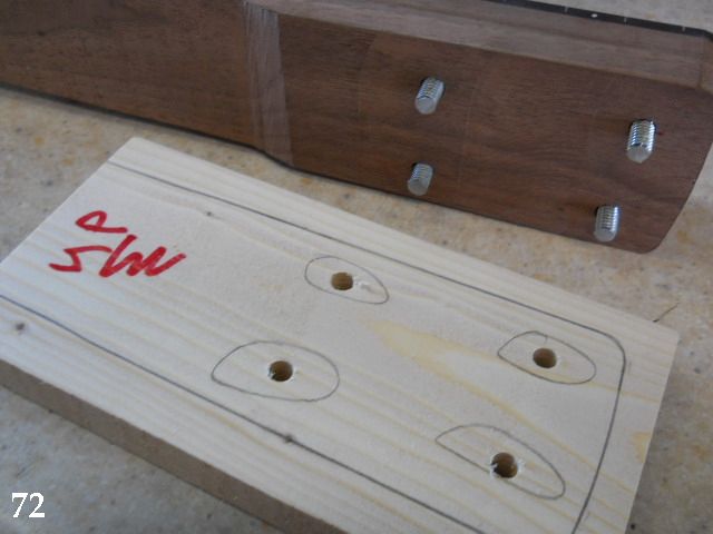
72. The “dents” are used to accurately drill the neck mounting bolt locations. They can be drilled 17/64” to more easily fit the all-thread stubs into the drilled holes. The neck is positioned against the wood and the outline drawn so it can be cut and sanded to produce a neck pattern template.
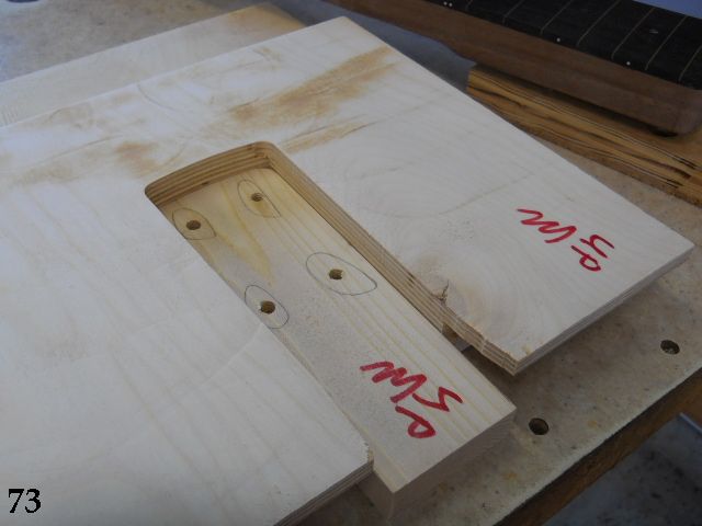
73. The template is shown dropped into the neck pocket routing jig to check the fit. This template will be used later to mark the hole locations in the pocket of the neck body.
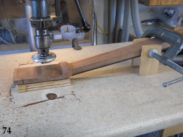
74. Time to plane the rear of the headstock to its finished thickness.
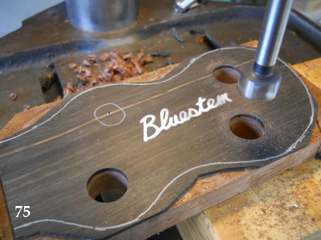
75. The nut blank is positioned against the fingerboard end, the overlay edge sanded to match the nut face, and glued in position. The tuner holes are drilled for the tuners that will be used. I didn't have the appropriate 11/16” Forstner bit so I drilled 5/8” and enlarged the holes to 11/16” by using the spindle sander. It was actually quite easy.
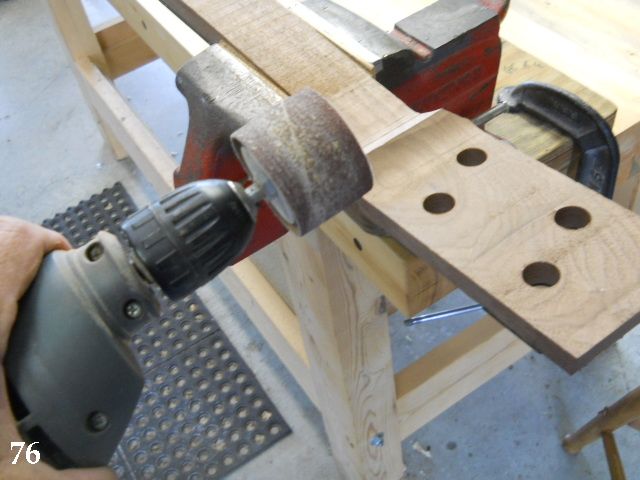
76. The volute (thumb stop) area is sanded to match the level of the neck and headstock rear face.
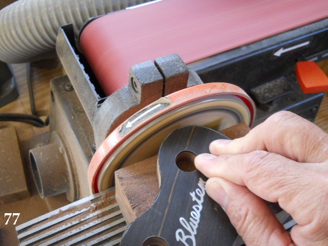
77. The headstock is cut out and sanded.
To be continued...
70. Here two of the sections have been glued and clamped with the third section being added. Once dry, the base layer is cut out and a bearing guided carbide router bit is used to pattern route the base layer to create the neck pocket routing jig.
71. A short section of wood a bit larger than the neck has the neck bolt locations transferred to the surface by inserting short sections of 1/4” - 20 all thread and “denting” the wood below.
72. The “dents” are used to accurately drill the neck mounting bolt locations. They can be drilled 17/64” to more easily fit the all-thread stubs into the drilled holes. The neck is positioned against the wood and the outline drawn so it can be cut and sanded to produce a neck pattern template.
73. The template is shown dropped into the neck pocket routing jig to check the fit. This template will be used later to mark the hole locations in the pocket of the neck body.
74. Time to plane the rear of the headstock to its finished thickness.
75. The nut blank is positioned against the fingerboard end, the overlay edge sanded to match the nut face, and glued in position. The tuner holes are drilled for the tuners that will be used. I didn't have the appropriate 11/16” Forstner bit so I drilled 5/8” and enlarged the holes to 11/16” by using the spindle sander. It was actually quite easy.
76. The volute (thumb stop) area is sanded to match the level of the neck and headstock rear face.
77. The headstock is cut out and sanded.
To be continued...