• TalkBass has been independent since 1998. Add your voice.
    Create a free account to reply to discussions, view embedded media, and browse with fewer display ads.
    Join freeLog in
    Want zero display ads or expanded classifieds tools? Compare plans.

30” Scale Compact Semi-acoustic Fretless Bass Build

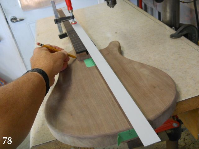
78. The neck is positioned carefully on the body to match the neck & body centerlines and the neck pocket location marked. The neck position is transferred directly from the (hopefully!) accurate drawing. It doesn't hurt to hook a tape measure over the end of the finger board to verify where the bridge saddle location of 30" (plus a bit for intonation correction) will be at the end of the body. It looks good to me, so it's time to commit to the neck pocket location.
tLGFKTt.jpg

79. The neck pocket routing guide jig is clamped in place and the neck pocket is routed. I do this in 1/16” depth increments until the correct depth (5/8”) is reached. The back edge of the routing guide was sanded to contour it so it could be clamped against the body to produce a uniform pocket depth.
VSMRG1E.jpg

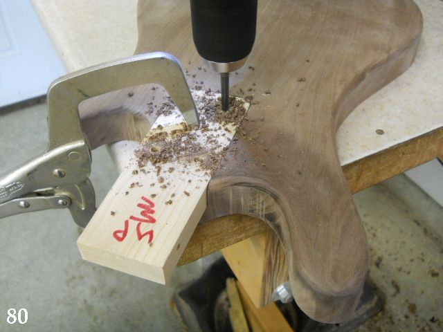
80. The neck mounting holes are transferred to the body location using the jig previously created.
cWvP0Dc.jpg

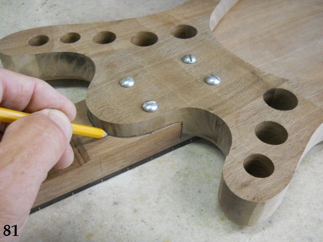
81. The neck is fastened temporarily in the pocket and the rear is marked where it intersects with the body.
Ua99JzF.jpg

More on the way...
 
Last edited:
82. The sides of the neck are marked with the guide lines for the 45 degree cut that will define the neck's rear shape. The location of the cut is transferred from drawing detailing the neck cross sections at the nut and 12th fret areas. The band saw is set for a 45 degree angle cut to remove waste material.
js2Pl3b.jpg

83. Here is an overview of the neck shaping process.
igxsXT8.jpg

84. Here the neck is sanded with a 6” long section of board covered in course sandpaper. This is done to ensure there are no peaks or valleys in the neck prior to sanding with the random orbit sander. (It's always good to have an audience!)
enh4kWr.jpg

85. The neck is being sanded with a foot-controlled 5” random orbit sander with 220 grit discs.
K2Zpcqw.jpg

86. The string locations can be marked directly from the drawing; I'm not a fan of measuring if I don't have to.
WIVEp2r.jpg

87. The nut is shaped and the string notches are filed just slightly higher than the fingerboard level marked on the face of the nut when it was fitted to the slot between the fingerboard and headstock overlay.
dJRbyFo.jpg

See ya'll later with more of this build...
 
88. The string locations were carefully laid out on the body and the 45 degree slanted string mounting holes and ball end recesses were added to the body. Tape at the location of the pickup also verifies that the strings will pass directly over the pickup poles. The body is quite strong even before the back is added, so this was a good time to add strings and test drive a bit. The dowel rod at the body is a bit forward of the final bridge saddle location, but no problem for preliminary check out. The top does contribute slightly to volume and has a distinctly woody tone, so it looks like this design is going to work out fine.
gTidfjt.jpg

89. A routing template is made for the pickup. It is made so the pickup has a bit of clearance completely around it. I tried to maximize the vibrating plate area for the top and fastening the mass of the pickup to the top would kill the minimal amount of acoustic energy produced, so the pickup will be mounted to the rear plate with the top free to resonate as best it can. The contoured piece of the top plate being held was routed out where the pickup will be located.
BsP2Qcd.jpg

Note: The pickup I'm using is a Guitar Fetish MM style from my spare parts box that needs special mounting provisions as the screw bosses that are normally on each side of the pickup have been removed as a result of a past use. This means I have to do a little creative mounting to use it here. If I were using the standard pickup I'd simply form the pickup route to accommodate those screw mount bosses and fasten the pickup to a block glued to the back plate with foam cushion under the pickup.

90. The Bass Clef “sound holes” are marked and drilled out; the large circular portion with a 1/2” Forstner bit and the curved portion with a series of drilled holes of various sizes. The outline is incised deeply with a “11 Exacto knife blade and the area between the drilled holes cut out with a jig saw.
yT9ks61.jpg

91. After the ports are cut out they are sanded using a shaped stick to hold the sandpaper. Note that the last 1/2" between the hole and the "arms" is left intact to add strength to the otherwise unsupported area. It is defined with a cut along the lines and the wood is carved away to create a bit of relief. The relief area is blackened with Magic Marker to better define the clef shape.
5iBIlwO.jpg

92. The location for the jacks and the volume controls is transferred to the sides and top plate. The volume controls are located 1-3/4” inward from the edge of the body.
2JcQ6I2.jpg

More to come...
 
Last edited:
93. The rear plate has the control cavity opening cut out by drilling a #60 hole and cutting the cover out with an extra fine fret saw blade. The shape and grain pattern will match perfectly, since the cutout is being used as the cavity cover.
tLJ2wbL.jpg

94. The rear plate is now glued in place. The central body section has glue carefully spread on its surface and the rear plate glued in place. A bit of care used to spread the glue will ensure minimal squeeze out inside the body cavity.
IFLGQV8.jpg

95. The neck mounting holes (drilled in step 80) are drilled through the back plate using a 1/4” drill bit. Short sections a 1/4” dowel are glued in place and 1/16” holes are drilled to locate the 1/2” Forstner bit centers. The counterbores are drilled to 1/4” depth. The holes can now by drilled through 9/32” to provide a bit of clearance for when the neck is attached.
WgCZYAL.jpg

96. The rear plate has a 1/4” thick ledge glued to the edge to support the control access cover plate. Cutting the control cover out with the extra fine blade saw provides an ideal grain match.
WBbFEuC.jpg

97. The holes that will house the output jacks are drilled with a 7/8” Forstner bit.
0H1LELy.jpg

Catch ya on the flip-flop...
 
This looks like it's becoming a highly desirable instrument, resulting from excellent craftsmanship and a slick design. I like & appreciate your choice to attach the heavy magnetic PU to the back, and I'm looking forward to your experiences with the piezo film. Will you load the piezo film purely vertical, or along the force line of the strings breaking over the bridge?
Thanks for this excellent thread!
 
  • Like
Reactions: Will_White
This looks like it's becoming a highly desirable instrument, resulting from excellent craftsmanship and a slick design. I like & appreciate your choice to attach the heavy magnetic PU to the back, and I'm looking forward to your experiences with the piezo film. Will you load the piezo film purely vertical, or along the force line of the strings breaking over the bridge?
Thanks for this excellent thread!
You're way over my head! The bridge transducer is a L.R. Baggs Element that I had in my extras box before this project was started. (I'm notoriously cheap...) The transducer itself looks like a flattened section of coaxial cable without an external jacket or covering. It will extend upward through the bridge base plate and lay in the saddle slot, between the saddle bottom and the bridge base. I'll cut the saddle slot just a bit loose, as the original installation instructions say that the saddle needs a slight amount of movement to convert the saddle movement to electrical energy.
It will be what it ends up being; I can always throw something else in later if it falls short of the mark.
 
98. The bridge outline is carefully formed in 1/2” thick Baltic Birch plywood. A scrap of 3/4” is screwed to the template and the shape is routed out with the bearing guided bit. This is done so the pattern routing bit can be used to create the shallow recess necessary to house the bridge base plate.
gal1AI3.jpg

99. The template is used to route a 3/32” deep pocket to hold the bridge base plate. I used cork to elevate the front edge of the routing template above the arched portion of the top plate. The routed recess is a bit deeper toward the back edge which works out even better for the string break angles over the bridge saddle.
eYhX2mA.jpg

100. The slot that will house the bridge saddle is routed to a 1/4” depth in 3/8” thick walnut. It is done twice here just in case I need to have a backup piece. It's much easier to route the slot and use the routing template to mark the bridge base plate outline to match the angle desired for the saddle than to try and cut the saddle slot after the base plate has been shaped. The outline is traced with the routing template, the base plate cut out and sanded to match the routed base plate recess in the top plate. The top edges of the base plate are then angled and sanded to blend them up to the saddle slot.
pntBKm2.jpg

101. The bridge base plate shape was traced on the slotted block shown above, cut out, and carefully sanded to shape so it would drop into the recess routed in the top plate. This setup locks the bridge in position and prevents it from moving when string pressure is applied. The volume control holes are drilled and the Dunlop Straploc buttons installed. I prefer to recess them as I keep the strap mounted to the body most of the time. With the exception of doing the electronics it's fully playable at this time, so might as well check it out before going any farther. Now's the time to determine if there are any changes to be made in neck angle, string height, etc. It sounds great, is a bit louder than any of my solid bodied basses, has a distinctly acoustic tone, and balances really well even without the additional weight of pickup, controls, and output jack hardware. Oh, and it plays like the proverbial butter!
QV7ACIE.jpg

102. Since I'm satisfied that everything is to my liking I made up a height gauge to assist with mounting the pickup at the desired height once the strings are removed.
YNziDtV.jpg

See ya'll later...
 
Last edited:
The bridge block, standing free in the recess, is an effective, flexible & clever design!

Thanks.
Hi Ortsom,
Yes, it works very well. The back edge is supported by the body's central frame area while the main portion of the bridge base sits directly on the 1/4" top plate, minus the amount it is inset. It seems very stable and the shallow pocket locks the bridge base to the top, preventing it from scootching out due to the angular contact exerted by string pressure. I'm very pleased with how the geometry has all come together on this design. Any time that you attempt to design using "common sense" there's often a fly presented in the ointment. We're doing fine so far!
 
It seems very stable and the shallow pocket locks the bridge base to the top, preventing it from scootching out due to the angular contact exerted by string pressure.
I had this problem when I made a similar instrument. I ended up gluing a "bridge holder" with a slot in it to the front of the bass. Then I carved a compensated string saddle piece that fit in the slot. That instrument was a great learning experience, looks like you've already learned a lot of what I went through prior to building this one. :-D
 
I had this problem when I made a similar instrument. I ended up gluing a "bridge holder" with a slot in it to the front of the bass. Then I carved a compensated string saddle piece that fit in the slot. That instrument was a great learning experience, looks like you've already learned a lot of what I went through prior to building this one. :-D
Hi Jisch,
Thanks for the link, I'm going back and reading your entire build article, as this one has a lot in common with it.
(For those unfamiliar with that build topic by Jisch, Four string fretless acoustic/electric (chambered) )

There are most likely a bunch of similar topics that I'm unfamiliar with, as these build topics seem to be pretty popular. Luckily I have a lot of practical experience with various types of instrument construction, so that's probably helped me avoid any major train-wrecks. After doing musical instrument and general woodworking stuff for 30 years I can sometimes see (and avoid) some of the major sticking points that I might otherwise run up against. One thing that helps a lot is a well thought out drawing. It really helps to visualize the entire process before the first board is cut.
 
Last edited:
  • Like
Reactions: Jisch
103. Blocks are cut and glued in place to allow mounting of the pickup through the sound ports. The blocks are angled on the bottom so the mounting surface is flat and parallel to the top plate opening. If a standard pickup is used a simple block could be added below the opening, but my pickup has had the side bosses removed from a previous use, hence the need for “creative mounting”.
bZOukKI.jpg

104. My particular pickup required the “creative mounting” shown here. The pickup is tucked in on the first string side and the stainless steel “ear” is rotated once it is inside the body. The pickup is then anchored to the blocks glued to the rear plate by pilot drilling for the mounting screws and inserting them through the clef cutouts. It sounds difficult, but its really simple to do. It would have been a bunch easier with a stock pickup, but again, I'm “frugal” and re-using this previously modified MM-style pickup.
5QLhUvv.jpg

105. The jack plate recesses are routed. Not strictly necessary, but it's one of those nice touches that add a bit more to a more professional appearance when everything is assembled.
4LsOzD7.jpg

106. The two black knobs used here started life as Radio Shack knobs. They were sanded to reduce diameter and height and polished by tightening them down on a short piece of 1/4” rod and sticking them in the drill press chuck. I used these when I produced lap steels and like them, but I might do a pair of turned wooden knobs. I'll live with these for a bit and then make a decision on that.
afLATss.jpg

107. The magnetic pickup was attached to the mounting blocks and the Baggs Element transducer was positioned in the saddle slot after drilling an access hole at the end of the slot and extending through the top plate. Everything was assembled yet again to finish up by adding the electronics and doing one last test drive before completely disassembling for finishing. The wiring details will be on the full construction drawing that I'll add in pdf form.
6dvUYlw.jpg

Did I plug it in? You bet. I ran the individual outputs to my SWR Workingman's 12 through a small mixer to check both the magnetic and the piezo bridge pickup. I'll have to say I was a bit astounded at the bridge pickup tone and output level and I could be totally happy with only the bridge pickup, I do want the option of having the magnetic available if I want it, though. I'll get some sound files or Video demonstration done later, but first it's going to require my normal three day finish procedure. I'm thinking that may raise a few eyebrows…