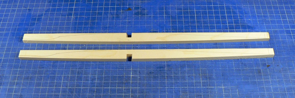
Starting with the X-brace. As I mentioned earlier, the shape of the trough is exactly the same as a spline curve with the same length and deflection drawn in CAD. So, as an experiment, I stretched that curve in CAD to the length of a line drawn diagonally through one half of the X-brace, printed it out and stuck the print to a piece of brace wood. I sanded the wood as near as I could to the curve and it fitted almost perfectly onto the trough. So I made two braces like that and notched them.
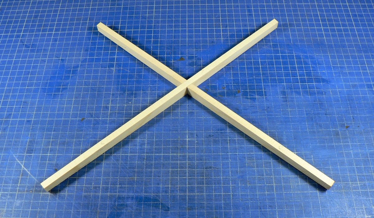
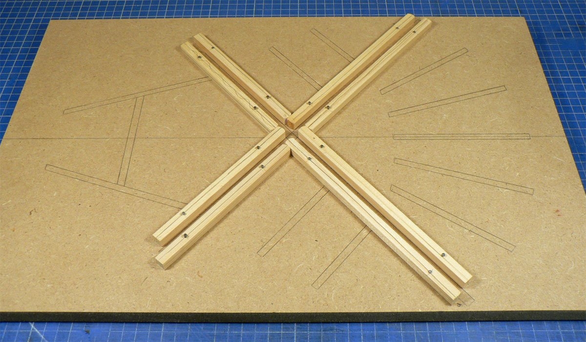
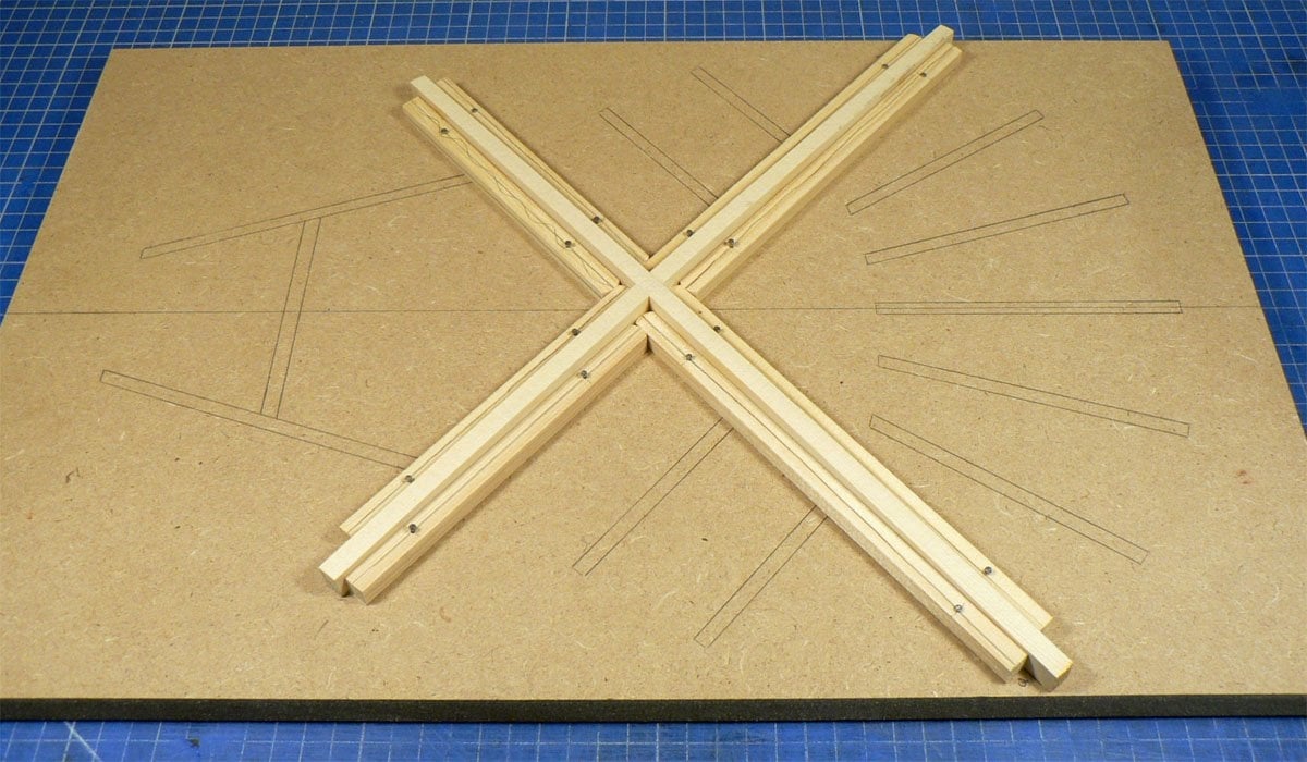
To be able to sand them to a perfect fit I made a sanding fixture. I marked out all the brace positions on a piece of MDF and pinned 'stickers' to it .
Here it is with the X-brace installed.
I pencilled the surfaces of the brace and It only took a few passes on the trough for all the pencil marks to disappear.
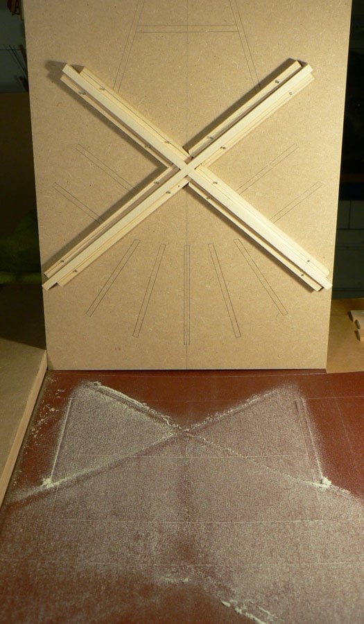
To be able to sand them to a perfect fit I made a sanding fixture. I marked out all the brace positions on a piece of MDF and pinned 'stickers' to it .
Here it is with the X-brace installed.
I pencilled the surfaces of the brace and It only took a few passes on the trough for all the pencil marks to disappear.