
- Feb 16, 2008
- 21,240
- 23,636
- Disclosures
- John K Custom Basses

TalkBass has been independent since 1998. Add your voice.
Create a free account to reply to discussions, view embedded media, and browse with fewer display ads.
Join free Log in
Want zero display ads or expanded classifieds tools? Compare plans.

here's the OPA2134 with 220R's and 1K's for R17/R18 @ -10db:
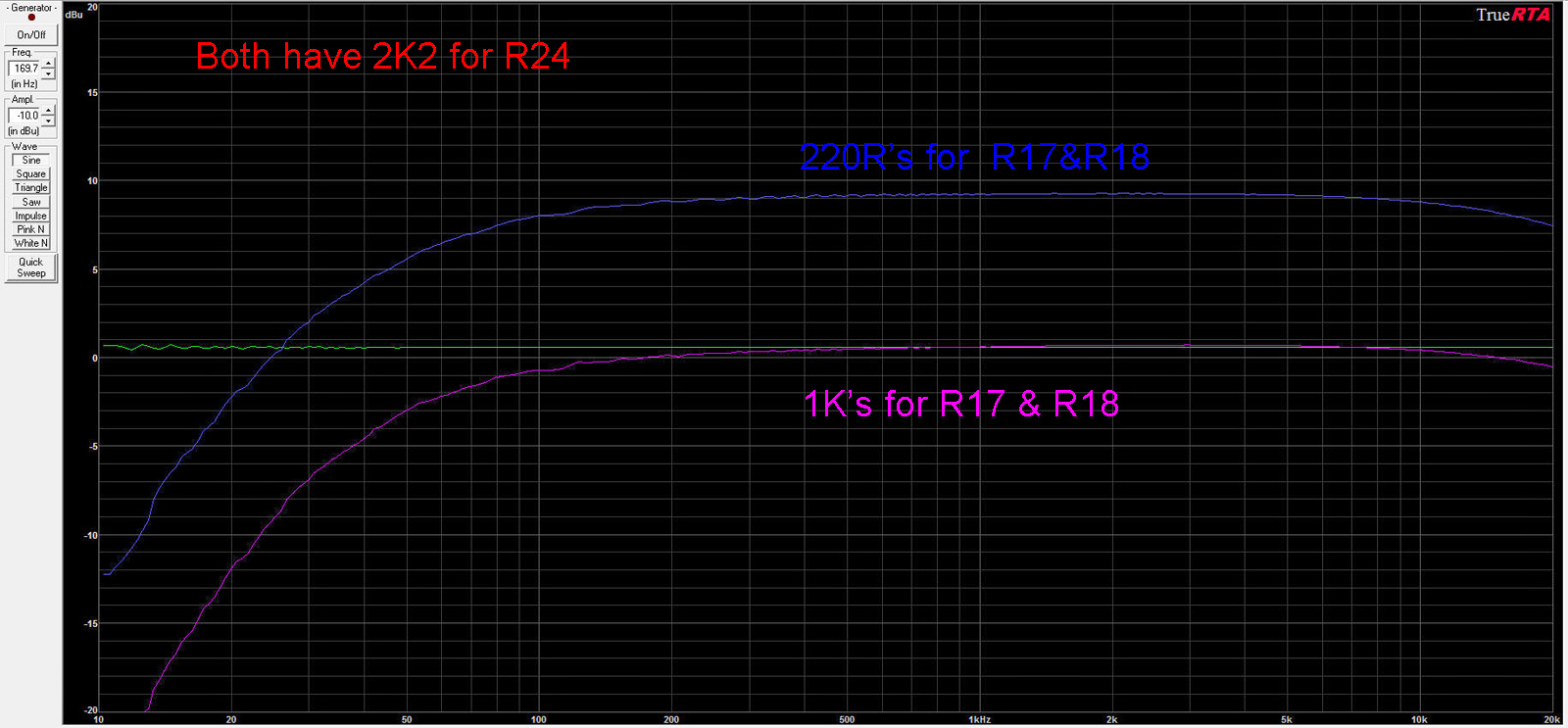
If you put that 220R in for R24 with R17/R18 at 220R the blue trace should be very close to the violet trace. But since decreasing the resistor values didn't have a positive outcome I would say keep the 1K's for R17/R18 and 2K2 for R24. Those 4.7uF capacitors for C5/C11 should improve the low end response a little bit.
When the LED's were across the primary, did it have a crunchier sound? I know the output was low because of the lower voltage across the primary, but how was the tone?
-Frank
yeah, i'd change C1 to a 1u. look at it now with the two 4u7's and a 1u for C1:Let's keep the 4.7uF's because it brought the response at 20Hz up by approx 5dB.
I'll make the changes to the schematic with the 220R's, no LED clipping and an optional note for the emitter 1K's on Q1/Q2.
Am I forgetting anything?
-Frank

yeah, i'd change C1 to a 1u. look at it now with the two 4u7's and a 1u for C1:
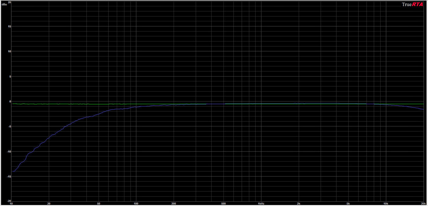
BTW, it sounds great and I prefer 220R's for R17 & R18. it can get pretty dirty that way and the freq response is the same as with the 1K's.
IMO, it's DONE!!!!
 I was playing around with LF resonance in the simulator that might be just what this circuit needs. Put a series cap of 22uF to the tranny primary pin 2... I'm showing a 3dB bump at 22Hz.
hmmmmm. just tried it with the 22u and there's absolutely no difference.
whether your simulations are off or not, the circuit sounds great just the way that it is right now.My simulations have been off from the actual circuit.

IMO, I don't think that any coupling cap will make a difference there since, with a value at 10u or above it's basically acting like a straight wire, unless i'm missing something(?).
The tranny primary coil and a series capacitor make a tank circuit that has a resonance frequency... that's the principle behind how they make wah pedals. If the capacitor in series with the coil is large enough, there won't be a resonant bump in the audio range and it acts more like a coupling capacitor that you would see with a resistive load. But if the cap is sized just right you can bump up the lowest frequencies in the audio range. The series resistance with the tank circuit limits how large the resonant bump can be. I just thought it would be an interesting experiment and if it worked out....-Frank
that's it, except I have a 2K2 for R24 on mine. I also have an OPA2134 for U2 in mine right now, but IMO, it doesn't really make any difference if you use an RC4558 (it draws 10ma less with the RC4558).
the whole circuit draws 20ma (with two 4558's, and 30ma with a 4558 and an OPA2134.


