
Enjoy the benefits of a premium membership!
Upgrade Account
-
TalkBass has been independent since 1998. Add your voice.
Create a free account to reply to discussions, view embedded media, and browse with fewer display ads.
Join free Log in
Want zero display ads or expanded classifieds tools? Compare plans.
You are using an out of date browser. It may not display this or other websites correctly.
You should upgrade or use an alternative browser.
You should upgrade or use an alternative browser.
Any amateur builders using their own CNC?
- Thread starter Jeff Siddall
- Start date
More options
Who Replied?
I'm going to offer another opinion. F360 rocks and is an excellent choice and paying for it will save you money even as a hobbyist. I teach CAD CAM CNC at a makerspace and all the classes are done in Fusion and almost all of the production done by our members is in Fusion. Rhino being a distant second. Though I'm sure it gets done I can't think of a single project done on our CNC's that wasn't done in F360 or Rhino. I'm the only member with the paid version, everyone else uses the student version.
Fusion is complete, it does everything from line drawing to exporting gcode and it's fully parametric and self contained. I can finish a guitar model, change my mind about the scale and string spacing and in seconds have updated gcode ready to cut the new dimensions.
Fusion is complete, it does everything from line drawing to exporting gcode and it's fully parametric and self contained. I can finish a guitar model, change my mind about the scale and string spacing and in seconds have updated gcode ready to cut the new dimensions.



The priests of Syrinx have assumed control.wow ok I didn't use poopie but that's ok.

I consider myself as a very very amateur builder. Few acoustic instruments done so far and a single electric bass (copy of Fender JB), all done without cnc. For another project, I have build a DIY CNC based on a simple, yet sturdy design involving 3D plastic printed parts and 25 stainless steel conduit. Total parts cost <450$, I printed my own plastic parts and bought a kit with control board, motors and misc hardware here V1 Engineering Inc | DIY Micro Manufacturing Machines and Supplies. First build with a 400x300mm workspace demonstrated good accuracy for woodworking. Using Fusion360 for CAD/CAM and Octopi for CNC control. Now planning to upscale to 900x400mm to carve a couple of bass bodies and neck. Total cost for upscale <50$ (MDF and plywood for larger base/spoilboard - 3x 1,2m conduit - 4m GT2 pulley ). Let you know how it turns out.

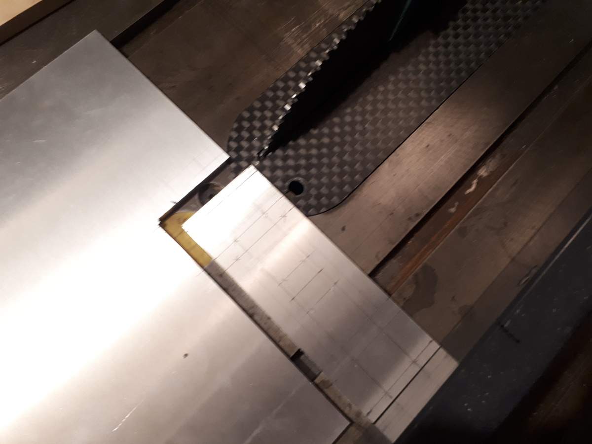
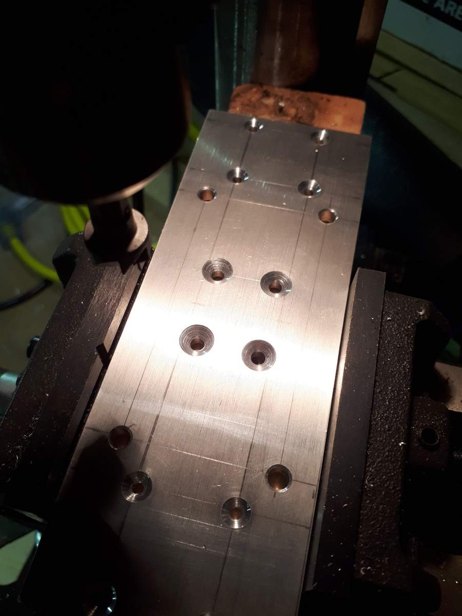
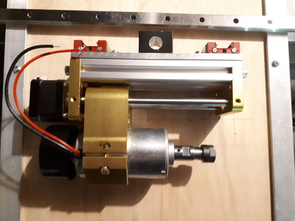
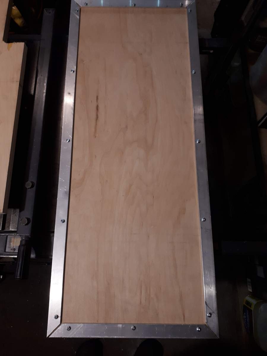
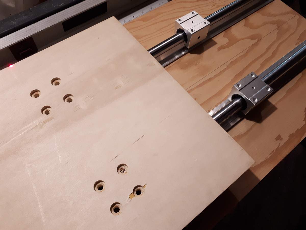
It's been almost 2 years since I started designing my upgraded CNC so based on my "typical" 2 year project timing I am right on track for actually making some progress on it. Over the weekend I cut the Z-axis mounting plate, mounted aluminum angle reinforcements to the table, installed the Y-axis linear rails, and mounted the X-axis linear rails to the base. I realized I was short two different kinds of screws so had to order some more, but final assembly could start in the next week or so once those arrive. All the measuring (and remeasuring), cutting, drilling, recessing, countersinking and chamfering all takes a long time, but so far so good!


I am fascinated by this in direct proportion to my complete ignorance on the mechanics and software. With my ultra-low build output, I couldn’t justify the expense, but there is a local Maker Space that supposedly has a CNC I’d like to check out for stuff like fingerboard inlays.
I am fascinated by this in direct proportion to my complete ignorance on the mechanics and software. With my ultra-low build output, I couldn’t justify the expense, but there is a local Maker Space that supposedly has a CNC I’d like to check out for stuff like fingerboard inlays.
The mechanics part is pretty straightforward: it's wood and metal held together with screws. So... kinda like a bass, except typically with more metal and less finishing. Unfortunately, unlike a bass, a CNC makes an unpleasant sound when used.

The software part is a bit up to you. Many people assume CAD/CAM is required, but it really isn't. You can even manually control a CNC with commands (G-code). Ex: if your machine is at the origin/home position and you send:
G01 X2
It will move 2 mm (or 2" if in imperial units). Send:
X0
and it will move back. Easy!
The expense part doesn't have to be huge either. Mine cost somewhere in the mid-$300 US range. I have only made 3 basses in my life so I think I qualify for ultra-low output!
Having said all that, if you have access to one already then definitely do that. Building your own is a lot of work.

Clearly you haven't heard me play.Unfortunately, unlike a bass, a CNC makes an unpleasant sound when used.
With a some more time over the holidays, and a lot more time over the past few weekends, I now have the CNC assembled and finished except for the spindle motor controller. Warning: this will be a long post. I probably should have posted updates as I went along but it was always too late by the time I packed up for the night 
Part of the reason it took so long was the number of new custom parts I ended up needing. In several cases I had just planned to screw two parts together and call it good. Unfortunately, after some trial and error I found that, to prevent binding, or provide the level of precision I was looking for, or just ease assembly, adjustable or removable mechanisms needed to be built into many places.
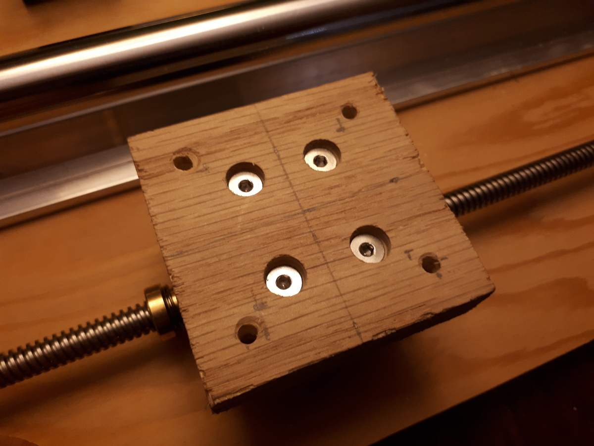
Custom lead screw spacer block of the right thickness that fastens from the back:
Bored-out Y-axis lead screw mounting block that allows mounting the anti-backlash nut entirely inside the block:
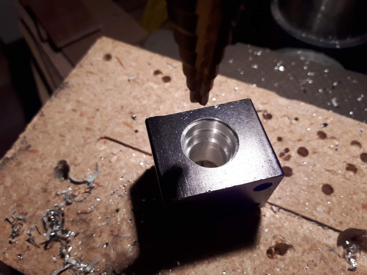
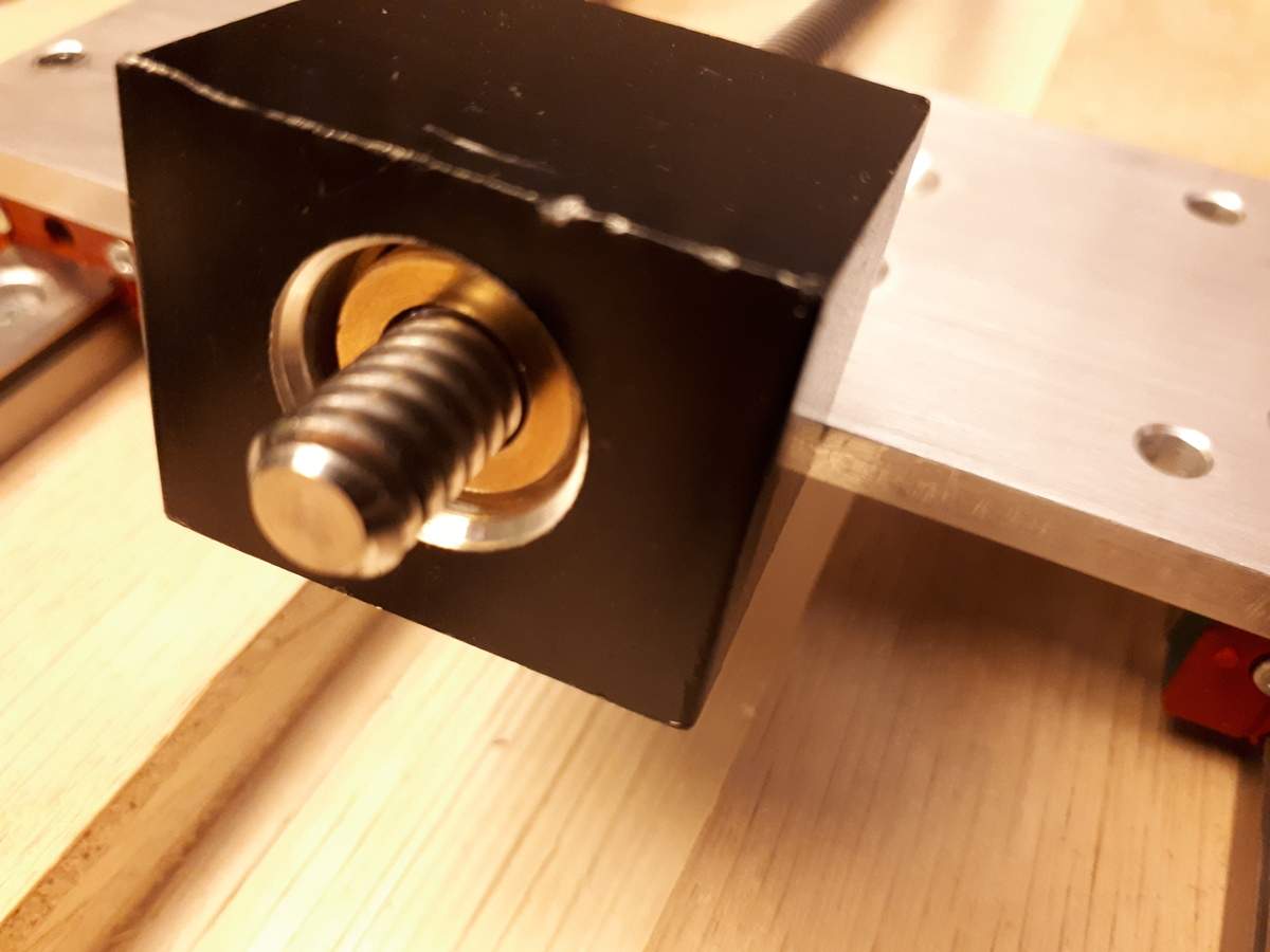
This allows me to use the maximum possible travel of the re-used Y-axis lead screw.
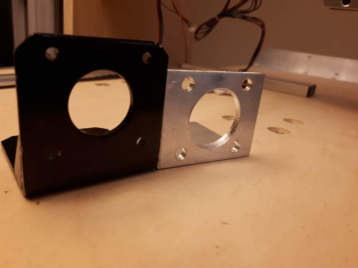
Custom X-axis stepper motor mount, required because the off-the-shelf one was too tall to clear the table:
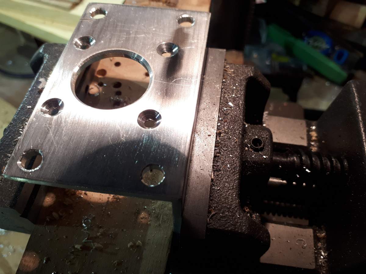
Custom Y-axis stepper mount that allows adjustment from the outside of the gantry with a flange that also protects the motor from impacts:
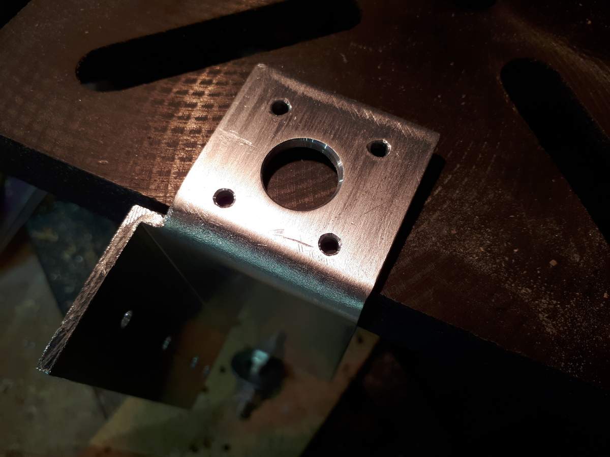
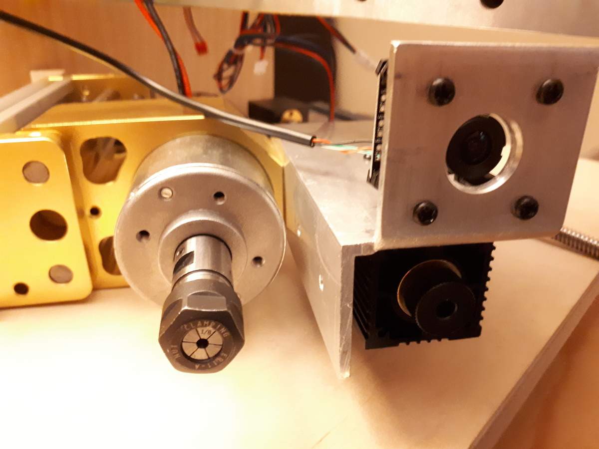
Custom LASER/microscope mount that attaches to the outside face of the Z-axis to allow laser cutting the full length of the Y-axis:
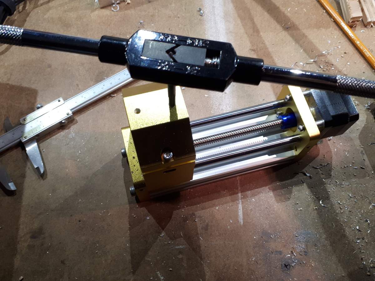
Mounting that also required tapping some new M5 holes in the Z-axis extrusion, and cutting those mounting screws to a custom length so they had enough thread to hold but didn't contact the spindle motor:
Here it is all mounted. The microscope and LASER are both mounted above the bottom of the bracket so neither will be damaged if the Z-axis crashes into a workpiece from the top:
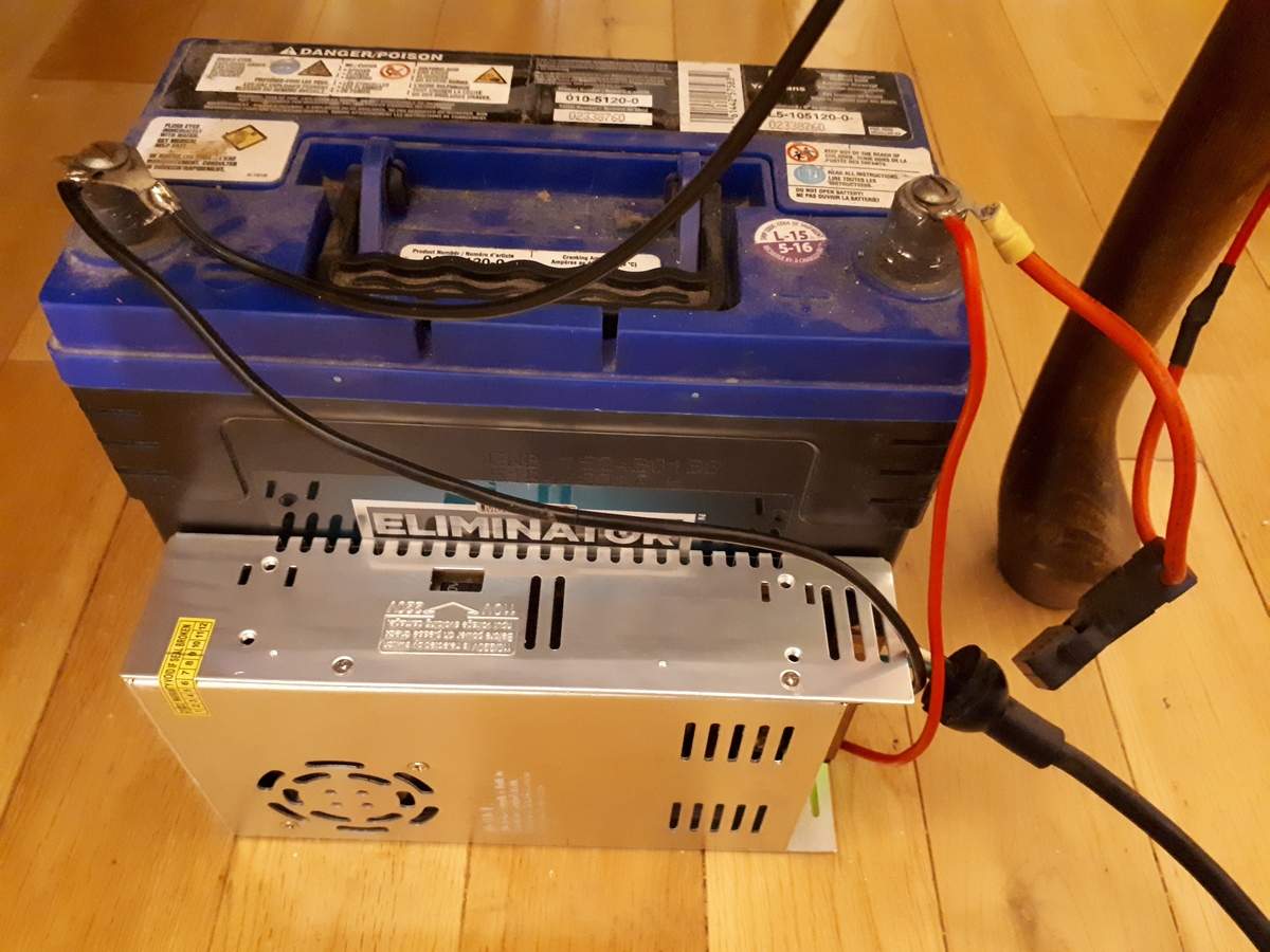
Once that was taken care of I added some other electronic things that I wanted. First, since my plans for this CNC will frequently result in working on valuable/irreplaceable pieces, I didn't want to have something like a power outage spoil anything. To solve that I made everything DC powered, and then built a battery backup to keep the entire CNC running for at least an hour in case of a power outage. Here's the battery and charger setup:
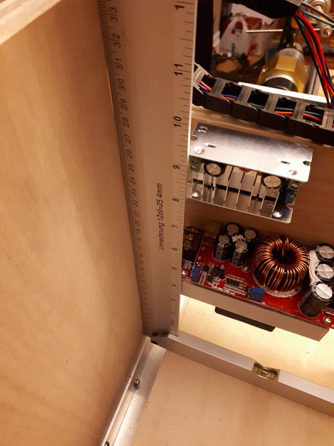
That meant inverters for the CNC controller, spindle driver, and laptop. Thankfully those were relatively inexpensive, even the 1500 W/30 A step up converter:
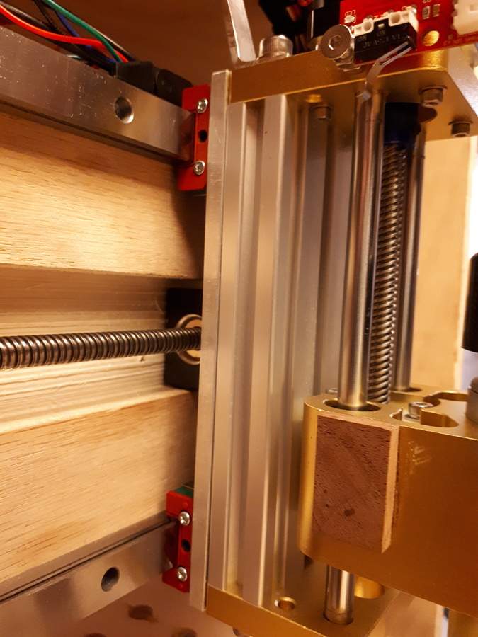
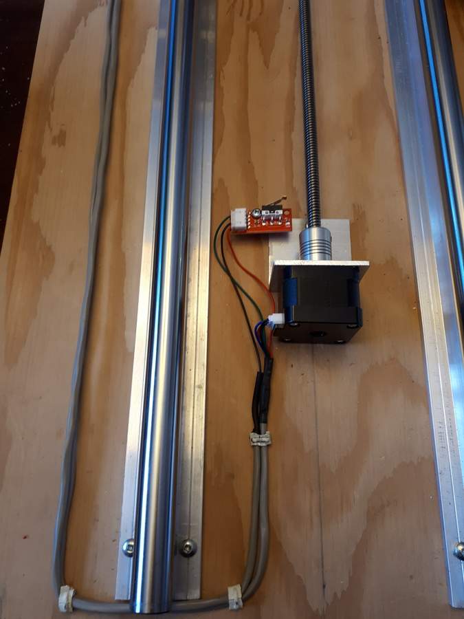
Second, I added homing switches on all axes so the setup would self-calibrate. Turns out those mircoswitches work great. In less than a minute after power-on it is ready to use at an accuracy into the hundredths of a mm (a few mils). Plenty good for wood work! Of course, even those required some custom mounting fixtures. Z-axis:
X-axis:
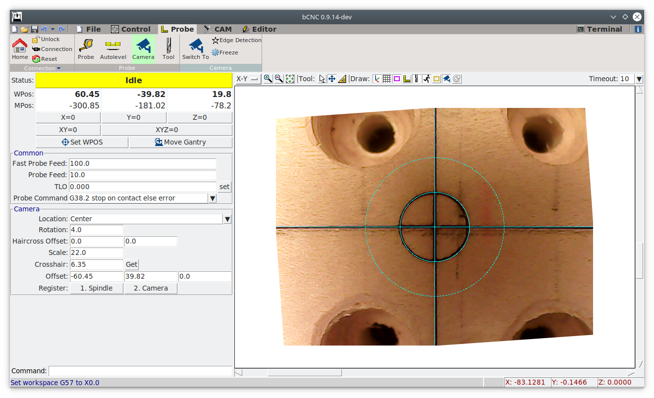
Then there is the digital microscope. These are pretty inexpensive, but once calibrated allow for amazingly precise optical alignment. I mounted mine at a relatively large distance (36 mm or about an inch and a half) from the workpiece to allow for cutting deep pockets, and it still achieves about 0.05 mm (about 2 mil) per pixel resolution. Here is a screenshot of the microscope target (teal solid line) over the 6.35 mm (1/4") LASER engraved target on the table immediately after the homing cycle with no manual adjustments:
After that, I put some significant effort into setup and calibration. I built some custom buttons into bCNC to perform handy functions, like jumping between the LASER, microscope and spindle positions. Another button prompts for stock thickness and then moves the Z-axis to the right focal length above the stock for perfect camera and LASER focus. I have used that one a bunch already. I also wrote some G-code to engrave a standardized optical target. This will allow me to engrave the target onto some unused part of the stock which can then be used to perfectly re-align the piece if I need to take it off the table to do some non-CNC work, then put it back on the CNC to continue.
I also setup a few WCS: G54 for the traditional right/rear/top home position, G55 with the Z axis at the focal distance to the table, G56 with a front/left/bottom origin, G57 for the center of the table. I use G58 and G59 as temporary work coordinates for projects.
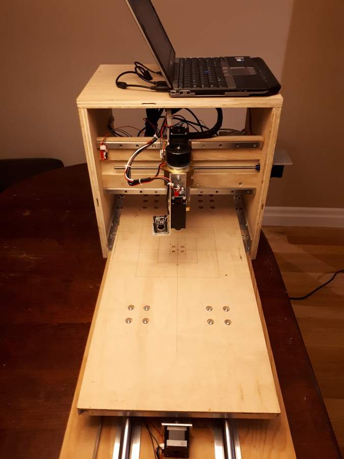
So here it is in finished form:
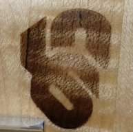
Unfortunately, due to the way the controller board is designed, I needed to order a couple more parts to get the PWM motor control working properly and am still waiting for those to show up. Until I get the spindle working I fiddled with the LASER instead. After increasing the tension on the anti-backlash nut springs, and fiddling with acceleration and maximum speed settings, I managed to get some pretty nice engraving. Here is the rear headstock logo for my recently finished fretless:
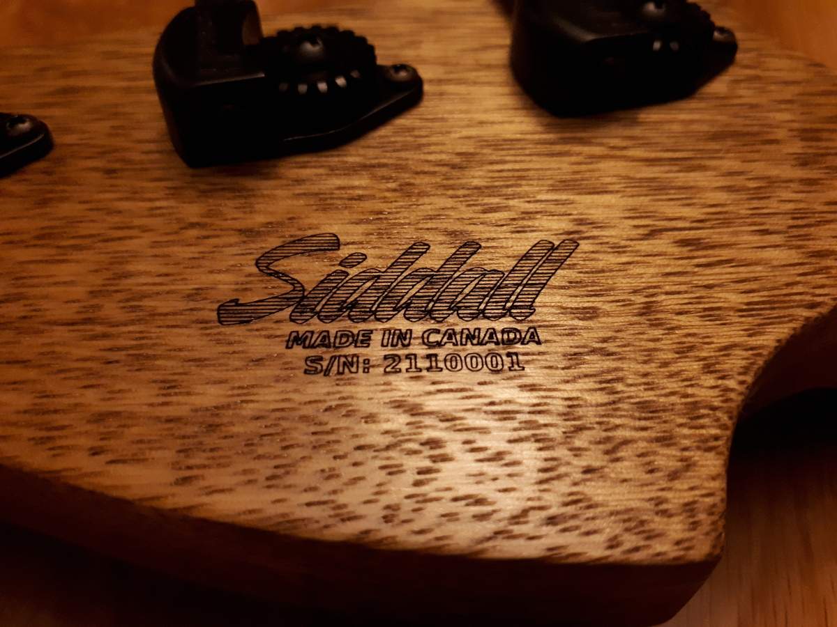
To give an idea of scale, the long lines of the forward slash between the S and the N above are 0.27 mm (0.011") apart.
I gotta say, sticking a finished bass, which I worked on for nearly 2 years, onto a CNC table was more than a bit nerve-wracking, but it turned out as well as I hoped. The fact that I could fit a long scale bass -- body and all -- onto it was pretty cool.
Click here for a short a video of the engraving in progress.
Total cost for the upgrade, including the new Z-axis, X and Y-axis linear rails, lead screws, the plywood, aluminum, fasteners, misc. hardware, power converters, microscope and limit switches, was $450 CAD, or about $360 US at current exchange rates. I'm really pleased with the tool I have for that price. Looking forward to testing the router!
Part of the reason it took so long was the number of new custom parts I ended up needing. In several cases I had just planned to screw two parts together and call it good. Unfortunately, after some trial and error I found that, to prevent binding, or provide the level of precision I was looking for, or just ease assembly, adjustable or removable mechanisms needed to be built into many places.
Custom lead screw spacer block of the right thickness that fastens from the back:
Bored-out Y-axis lead screw mounting block that allows mounting the anti-backlash nut entirely inside the block:
This allows me to use the maximum possible travel of the re-used Y-axis lead screw.
Custom X-axis stepper motor mount, required because the off-the-shelf one was too tall to clear the table:
Custom Y-axis stepper mount that allows adjustment from the outside of the gantry with a flange that also protects the motor from impacts:
Custom LASER/microscope mount that attaches to the outside face of the Z-axis to allow laser cutting the full length of the Y-axis:
Mounting that also required tapping some new M5 holes in the Z-axis extrusion, and cutting those mounting screws to a custom length so they had enough thread to hold but didn't contact the spindle motor:
Here it is all mounted. The microscope and LASER are both mounted above the bottom of the bracket so neither will be damaged if the Z-axis crashes into a workpiece from the top:
Once that was taken care of I added some other electronic things that I wanted. First, since my plans for this CNC will frequently result in working on valuable/irreplaceable pieces, I didn't want to have something like a power outage spoil anything. To solve that I made everything DC powered, and then built a battery backup to keep the entire CNC running for at least an hour in case of a power outage. Here's the battery and charger setup:
That meant inverters for the CNC controller, spindle driver, and laptop. Thankfully those were relatively inexpensive, even the 1500 W/30 A step up converter:
Second, I added homing switches on all axes so the setup would self-calibrate. Turns out those mircoswitches work great. In less than a minute after power-on it is ready to use at an accuracy into the hundredths of a mm (a few mils). Plenty good for wood work! Of course, even those required some custom mounting fixtures. Z-axis:
X-axis:
Then there is the digital microscope. These are pretty inexpensive, but once calibrated allow for amazingly precise optical alignment. I mounted mine at a relatively large distance (36 mm or about an inch and a half) from the workpiece to allow for cutting deep pockets, and it still achieves about 0.05 mm (about 2 mil) per pixel resolution. Here is a screenshot of the microscope target (teal solid line) over the 6.35 mm (1/4") LASER engraved target on the table immediately after the homing cycle with no manual adjustments:
After that, I put some significant effort into setup and calibration. I built some custom buttons into bCNC to perform handy functions, like jumping between the LASER, microscope and spindle positions. Another button prompts for stock thickness and then moves the Z-axis to the right focal length above the stock for perfect camera and LASER focus. I have used that one a bunch already. I also wrote some G-code to engrave a standardized optical target. This will allow me to engrave the target onto some unused part of the stock which can then be used to perfectly re-align the piece if I need to take it off the table to do some non-CNC work, then put it back on the CNC to continue.
I also setup a few WCS: G54 for the traditional right/rear/top home position, G55 with the Z axis at the focal distance to the table, G56 with a front/left/bottom origin, G57 for the center of the table. I use G58 and G59 as temporary work coordinates for projects.
So here it is in finished form:
Unfortunately, due to the way the controller board is designed, I needed to order a couple more parts to get the PWM motor control working properly and am still waiting for those to show up. Until I get the spindle working I fiddled with the LASER instead. After increasing the tension on the anti-backlash nut springs, and fiddling with acceleration and maximum speed settings, I managed to get some pretty nice engraving. Here is the rear headstock logo for my recently finished fretless:
To give an idea of scale, the long lines of the forward slash between the S and the N above are 0.27 mm (0.011") apart.
I gotta say, sticking a finished bass, which I worked on for nearly 2 years, onto a CNC table was more than a bit nerve-wracking, but it turned out as well as I hoped. The fact that I could fit a long scale bass -- body and all -- onto it was pretty cool.
Click here for a short a video of the engraving in progress.
Total cost for the upgrade, including the new Z-axis, X and Y-axis linear rails, lead screws, the plywood, aluminum, fasteners, misc. hardware, power converters, microscope and limit switches, was $450 CAD, or about $360 US at current exchange rates. I'm really pleased with the tool I have for that price. Looking forward to testing the router!
Last edited:
Good timing for this to pop back up, I bought a 3018 last year and have been mainly using it for cutting small parts for pickup making and other hardware odds and ends. Mine has some very minor upgrades (stronger spindle motor and upgraded Z axis). I'm planning either a large scale "upgrade" like you did, or a totally separate machine.
Did you ever do the upsize? How did it turn out? That's one of the machines I'm considering as a replacement. I've seen a couple people use them for guitar building but it does seem like they have a reputation for being a little flexy in larger sizes.
I consider myself as a very very amateur builder. Few acoustic instruments done so far and a single electric bass (copy of Fender JB), all done without cnc. For another project, I have build a DIY CNC based on a simple, yet sturdy design involving 3D plastic printed parts and 25 stainless steel conduit. Total parts cost <450$, I printed my own plastic parts and bought a kit with control board, motors and misc hardware here V1 Engineering Inc | DIY Micro Manufacturing Machines and Supplies. First build with a 400x300mm workspace demonstrated good accuracy for woodworking. Using Fusion360 for CAD/CAM and Octopi for CNC control. Now planning to upscale to 900x400mm to carve a couple of bass bodies and neck. Total cost for upscale <50$ (MDF and plywood for larger base/spoilboard - 3x 1,2m conduit - 4m GT2 pulley ). Let you know how it turns out.
Did you ever do the upsize? How did it turn out? That's one of the machines I'm considering as a replacement. I've seen a couple people use them for guitar building but it does seem like they have a reputation for being a little flexy in larger sizes.
I received my optocouplers, built the driver, tested, didn't work, then tested a bit and realized that the second schematic I found for the CNC controller was also wrong, did some more testing to figure out how the controller board really worked, redesigned the motor driver again, forgot to install the back EMF diode across the motor, fried the MOSFET, replaced it and finally tested successfully. Next step: first shavings! Good news, it all worked flawlessly. No problems cutting 2000 mm/min at about 2 mm depth on a 6 mm ball nose:
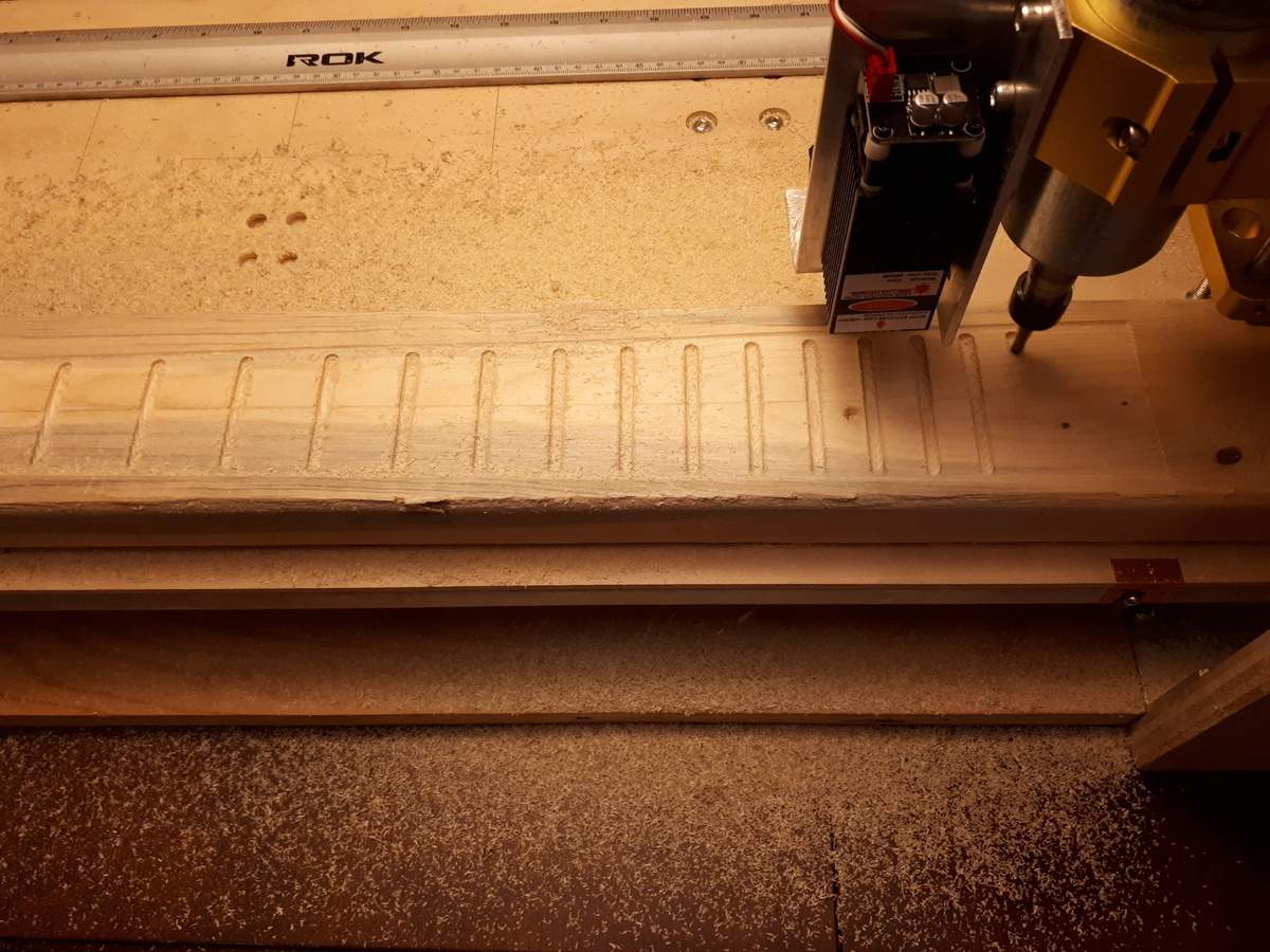
Done!
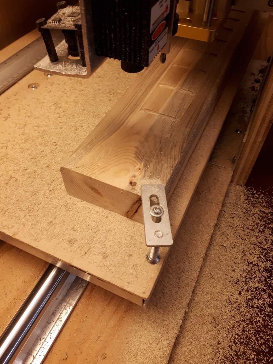
Granted, this was only a 2x4, but it still cuts infinitely better than the old 3018:
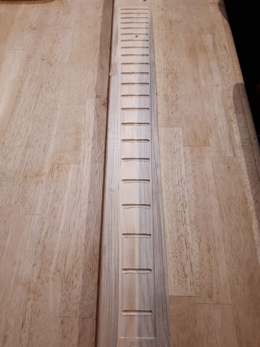
I stopped and restarted the job between each half and the slots, and inadvertently set the depth of the right side of the board above 1 mm deeper than the left. Oh well, just a proof of concept anyway. Here is a close-up:
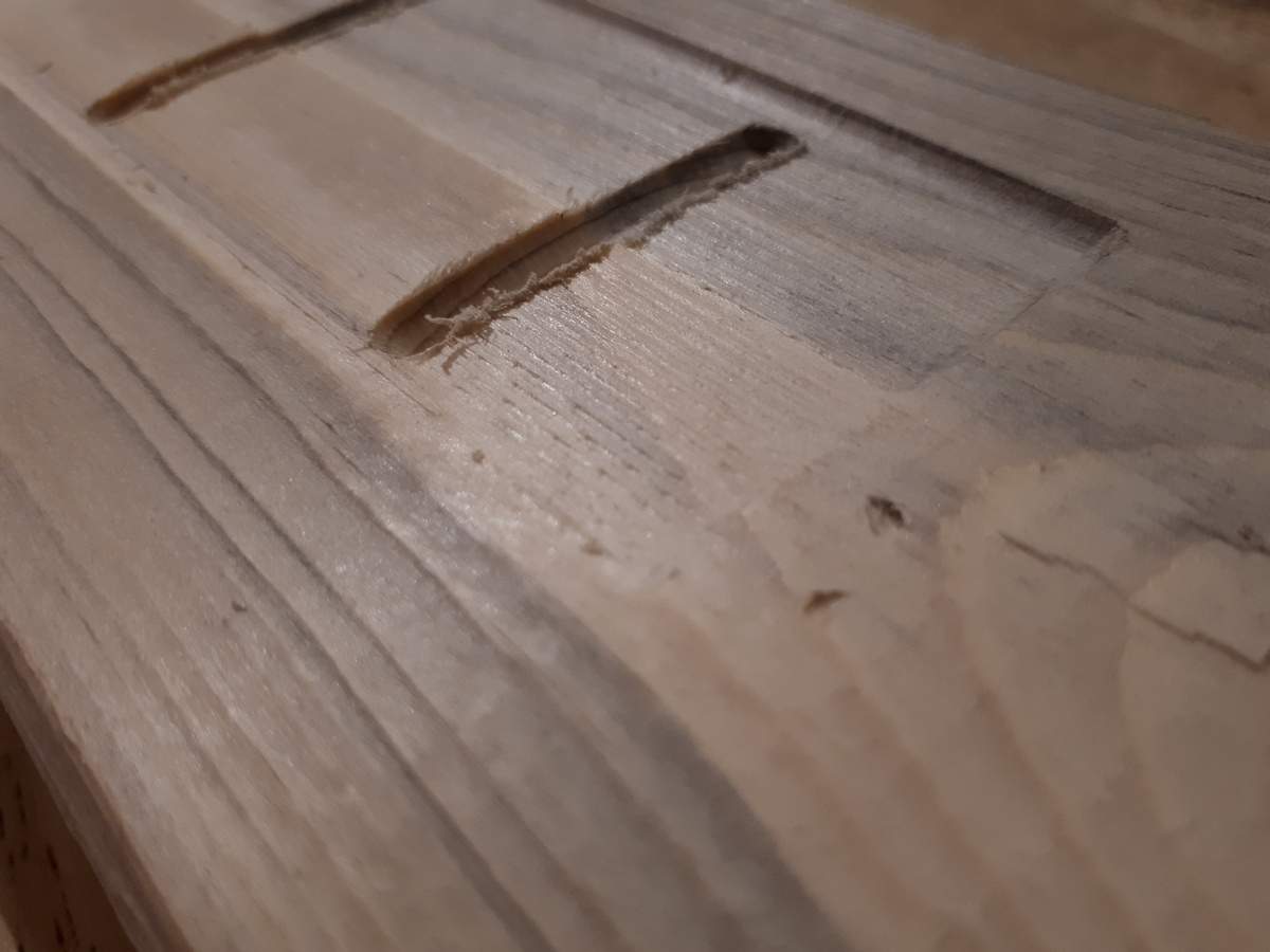
Also, some may have noticed that those fret slots are a bit wide
The CNC did do a tool change between the contouring and the slots, but because I was just experimenting I just left the same 6 mm ball nose in the machine for the fret slots.
I will try the teeny 0.023" fret slot bit next. If that all goes well then it will be onto a real hard maple board next.
Done!
Granted, this was only a 2x4, but it still cuts infinitely better than the old 3018:
I stopped and restarted the job between each half and the slots, and inadvertently set the depth of the right side of the board above 1 mm deeper than the left. Oh well, just a proof of concept anyway. Here is a close-up:
Also, some may have noticed that those fret slots are a bit wide
The CNC did do a tool change between the contouring and the slots, but because I was just experimenting I just left the same 6 mm ball nose in the machine for the fret slots.
I will try the teeny 0.023" fret slot bit next. If that all goes well then it will be onto a real hard maple board next.
Wow, 2mm depth at 2,000mm/min is wonderful! That's got to be like an order of magnitude better than a 3018 could do.
Wow, 2mm depth at 2,000mm/min is wonderful! That's got to be like an order of magnitude better than a 3018 could do.
Yes, probably more than an order of magnitude improvement. Now, to be fair, that was with only about 20% overlap per pass, and in softwood, but I still can't complain. On the deepest pass the spindle power was only about 30% of rating and with no hint of slowdown.
I forgot to mention in the first post, but I also tested the UPS by pulling the AC power plug part way through the job. Battery current was about 8 A. With a battery rating of 70 minutes of reserve capacity at 25 A it would theoretically run for about 4 hours.
I will post another update, and my final judgement once I have tested with hard maple but so far so good!
Another update from the past weekend. I was able to test the 0.026" fret slot mill and I am happy to report that:
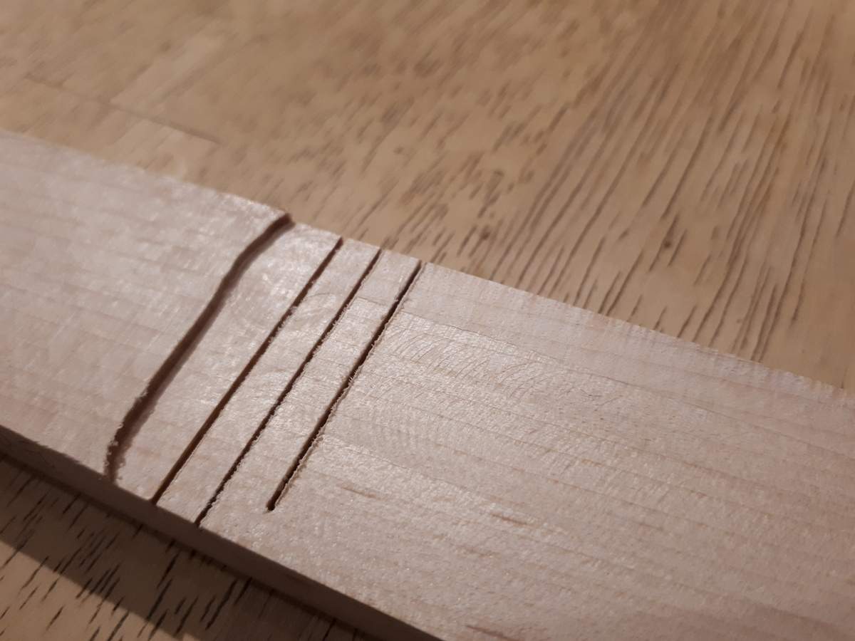
Unfortunately, in the process I discovered that even though plunging into the blind slot worked fine this time (it usually isn't a good thing with end mills) chip ejection was an issue because there was no empty space for the chips to go. I had to go back with a knife and clean out the surprisingly tightly packed slot. Rather than tempt fate again, I decided to implement a ramp into the slot generator portion of the script. This is less trivial than I initially expected because a normal linear ramp going from the top of one end of the slot to the bottom of the opposite end would result in overly-deep cuts in some parts of this curved-bottom application. That means my brain is hurting again while I figure out a better way to do it, but I think I have most of sorted now. Hopefully I can finish it and cut a real fretboard by this weekend.
- I have some slots
- I still have an intact end mill
Unfortunately, in the process I discovered that even though plunging into the blind slot worked fine this time (it usually isn't a good thing with end mills) chip ejection was an issue because there was no empty space for the chips to go. I had to go back with a knife and clean out the surprisingly tightly packed slot. Rather than tempt fate again, I decided to implement a ramp into the slot generator portion of the script. This is less trivial than I initially expected because a normal linear ramp going from the top of one end of the slot to the bottom of the opposite end would result in overly-deep cuts in some parts of this curved-bottom application. That means my brain is hurting again while I figure out a better way to do it, but I think I have most of sorted now. Hopefully I can finish it and cut a real fretboard by this weekend.
Last edited:

What about starting in the middle at the tip of the curved fingerboard, and then working your way towards each end with progressively deeper passes?
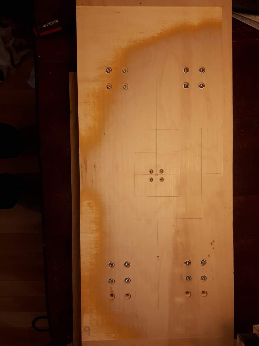
Just about forgot: I also flattend the bed with a 1/2" straight bit. It took two 0.1 mm passes (about 1/128" total) to get it flat but it is much better now. The plywood looks like a topographical map, and while I am sad that the maple veneer is partly gone (paper thin as it was!), I am happier that it is now flat to much better than 0.1 mm (4 mil):
What sort of end mill are you using? Any way to rig a vacuum as a dust collector with a nozzle right next to the bit?
What about starting in the middle at the tip of the curved fingerboard, and then working your way towards each end with progressively deeper passes?
That is a good idea, but keep in mind that the curved bottom of the slot matches the curvature of the board itself so you would still need a plunge/ramp operation.
I had considered doing multiple passes, to make shallower plunges, and that certainly would have been easier to implement. However, with these teeny bits you also have to go so slow that it would take nearly forever to cut that. These cuts were done at 40 mm/min.
The other consideration I had is that with very shallow passes the wear is all concentrated on the tip of the mill rather than all the way down the flutes, which I would prefer.
What sort of end mill are you using? Any way to rig a vacuum as a dust collector with a nozzle right next to the bit?
For this test I used a Kyocera 1640-0256.236, which is a 0.0256”, extended reach, 2 flute with 6 mm (0.236”) cut length. Interestingly, chip ejection was not really an issue with the through slots. Chips were flying out of there with surprising velocity and didn't need any air/vacuum assist. But nothing was ejected from the blind slot because it was all so bunched up right from the beginning. A ramp should provide a space for the chips to go in the blind slot so that is my current plan.


