

Enjoy the benefits of a premium membership!
Upgrade Account
-
TalkBass has been independent since 1998. Add your voice.
Create a free account to reply to discussions, view embedded media, and browse with fewer display ads.
Join free Log in
Want zero display ads or expanded classifieds tools? Compare plans.
You are using an out of date browser. It may not display this or other websites correctly.
You should upgrade or use an alternative browser.
You should upgrade or use an alternative browser.
Any DIY pedal builders on TB? Strut your stuff!
- Thread starter SubHuman
- Start date
More options
Who Replied?




Interesting, any details? Inside pics?
I use Tayda for parts, drilled enclosures, and screening. Their app is great for generating custom drill files.2 questions:
1) Where are people ordering their parts from these days? I need a few caps etc. Usually I'd just order from smallbear, but it's been a long time since I've ordered any parts. Where are people ordering from these days?
2) Has anyone played around with the coupling caps on muffs? I have a muff where I replaced the 100n caps with 220n caps and it sounds pretty good. But wondering if it's overkill. I have a new russian muff that I replaced a few caps with 220s but it's almost too much. I'd like to dial it back and wondering the best way. Halve the value to like 150ish... or will just changing one or two caps get me there?
I just read that the Pharoah uses 470n coupling caps throughout (not 47n as sometimes is reported). That sounds almost too high/too much bass, but people like it.
Invalid Link Removed
I've experimented a lot with the muff circuit. Sounds like maybe you are going for "more bass" with the larger coupling caps? I have a counter-intuitive take on this: The typical muff has too much bass, as well as too much bass clipping. So what I like to do is decrease the size of the clipping caps (try 33 or 39nF). This actually de-compresses the lower frequencies a bit. Enough that it might also be useful to also decrease the size of say the first coupling cap and get a bit tighter bass. Another trick I have is for adding "clean blend": instead of a separate clean circuit getting mixed back into the fuzz, you put resistors in series with the clipping diodes. I have had luck with values 2-3.3k. This eliminates the typical clean-blend phase issues, and is much easier as well. It's a fun circuit to experiment with!
I'm just finishing up a 2nd unit with prettier insides; will post ASAP.Interesting, any details? Inside pics?
In the meantime some details listed here:
https://www.talkbass.com/threads/walker-circuits-tachi-dual-band-bass-drive.1628946/

deepestend
Commercial User
- Feb 21, 2003
- 6,249
- 8,171
- Disclosures
- Website and Social Media at Sadowsky
I use Tayda for parts, drilled enclosures, and screening. Their app is great for generating custom drill files.
Invalid Link Removed
I've experimented a lot with the muff circuit. Sounds like maybe you are going for "more bass" with the larger coupling caps? I have a counter-intuitive take on this: The typical muff has too much bass, as well as too much bass clipping. So what I like to do is decrease the size of the clipping caps (try 33 or 39nF). This actually de-compresses the lower frequencies a bit. Enough that it might also be useful to also decrease the size of say the first coupling cap and get a bit tighter bass. Another trick I have is for adding "clean blend": instead of a separate clean circuit getting mixed back into the fuzz, you put resistors in series with the clipping diodes. I have had luck with values 2-3.3k. This eliminates the typical clean-blend phase issues, and is much easier as well. It's a fun circuit to experiment with!
@jw23mind nice post! How would you run the resistors in series? Just a resistor soldered on either side of each diode? Very curious because I’d like a little more of a clean blend sound without an actual clean blend.
also, interesting on the caps. I do like raising the value of the coupling caps but wonder if I can make 1-2 a lower value to tighten things up.
I mean, you can make ALL the coupling caps a lower value, but I find that small changes have a pretty big effect. Generally think of the early caps having more of an effect on the fuzz character, where the later caps tend to effect only the frequency response (pre vs post eq). Also the coupling caps directly feeding the clipping stages have a greater effect the compression as well (smaller=more compression).@jw23mind nice post! How would you run the resistors in series? Just a resistor soldered on either side of each diode? Very curious because I’d like a little more of a clean blend sound without an actual clean blend.
also, interesting on the caps. I do like raising the value of the coupling caps but wonder if I can make 1-2 a lower value to tighten things up.
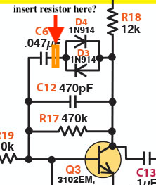
Regarding the series resistor: lift the clipping cap at one end, and insert the resistor, that will put it in series with the diodes. Consider doing this at both clipping stages.
I also like to lower the value of the hi-cut caps a little to open the top-end a bit (less muff-led).@jw23mind nice post! How would you run the resistors in series? Just a resistor soldered on either side of each diode? Very curious because I’d like a little more of a clean blend sound without an actual clean blend.
also, interesting on the caps. I do like raising the value of the coupling caps but wonder if I can make 1-2 a lower value to tighten things up.
deepestend
Commercial User
- Feb 21, 2003
- 6,249
- 8,171
- Disclosures
- Website and Social Media at Sadowsky
@jw23mind, all very interesting. So, on this diagram:
What are the hi-cut caps? C10, C11, C12? The 470/430/500pf ones?
Later caps effect the EQ: So, are you saying that larger caps for C2 and C3 make for more bass response? For C5 and C13, smaller caps will mean a more compressed clipping?
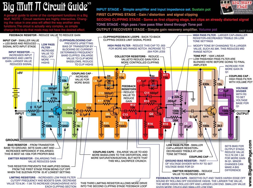
What are the hi-cut caps? C10, C11, C12? The 470/430/500pf ones?
Later caps effect the EQ: So, are you saying that larger caps for C2 and C3 make for more bass response? For C5 and C13, smaller caps will mean a more compressed clipping?
Last edited:
deepestend
Commercial User
- Feb 21, 2003
- 6,249
- 8,171
- Disclosures
- Website and Social Media at Sadowsky
@jw23mind Is this what you are talking about with the resistor? Just put it between the cap and the diodes?
Yes to all, and bass compression in particular.@jw23mind, all very interesting. So, on this diagram:
What are the hi-cut caps? C10, C11, C12? The 470/430/500pf ones?
Later caps effect the EQ: So, are you saying that larger caps for C2 and C3 make for more bass response? For C5 and C13, smaller caps will mean a more compressed clipping?
View attachment 5250690
Yes exactly@jw23mind Is this what you are talking about with the resistor? Just put it between the cap and the diodes?
View attachment 5250723
deepestend
Commercial User
- Feb 21, 2003
- 6,249
- 8,171
- Disclosures
- Website and Social Media at Sadowsky
Yes exactly
How does that work? Is it actually blending in more of the signal for a blend, or does it just attenuate the clipped signal?
Thanks again for any explanations...trying to learn more!

The opposite of attentuation; rather it is preserving a portion of the signal that would otherwise be lost to the clipping diodes.How does that work? Is it actually blending in more of the signal for a blend, or does it just attenuate the clipped signal?
Thanks again for any explanations...trying to learn more!
deepestend
Commercial User
- Feb 21, 2003
- 6,249
- 8,171
- Disclosures
- Website and Social Media at Sadowsky
The opposite of attentuation; rather it is preserving a portion of the signal that would otherwise be lost to the clipping diodes.
The muff I've been modding has a germanium clipping section with three slots for diodes that I have socketed all three. Last night, I put a 1-3.2K resistor in the first slot and LED's in the other two... I'm not sure if I could hear a huge difference, but I'll give it a go tonight with SI diodes.
I do think that you are right that using 430pf takes away some of the muffle and gives the clarity I was looking for.
I also replaced all of the 180 caps for 100 and slowly worked my way back from the end. I do think it sounds better with 180 coupling caps, but left the first two at 100.
keep experimenting there's no right or wrong, just depends on what you are going for. Don't be afraid to experiment with those resistor value: try something extreme like 10k and listen for the difference and learn.The muff I've been modding has a germanium clipping section with three slots for diodes that I have socketed all three. Last night, I put a 1-3.2K resistor in the first slot and LED's in the other two... I'm not sure if I could hear a huge difference, but I'll give it a go tonight with SI diodes.
I do think that you are right that using 430pf takes away some of the muffle and gives the clarity I was looking for.
I also replaced all of the 180 caps for 100 and slowly worked my way back from the end. I do think it sounds better with 180 coupling caps, but left the first two at 100.
Without seeing the schematic for the PCB you are are using I can't opine on what a resistor would do in that position. Is the resistor in series with the LEDs? Keep in mind the higher the voltage breakdown of the devices, the higher the resistor value would need to be to have an audible effect: LED would need a larger resistor than Si. It's all about balance and proportionality.The muff I've been modding has a germanium clipping section with three slots for diodes that I have socketed all three. Last night, I put a 1-3.2K resistor in the first slot and LED's in the other two... I'm not sure if I could hear a huge difference, but I'll give it a go tonight with SI diodes.
I do think that you are right that using 430pf takes away some of the muffle and gives the clarity I was looking for.
I also replaced all of the 180 caps for 100 and slowly worked my way back from the end. I do think it sounds better with 180 coupling caps, but left the first two at 100.
deepestend
Commercial User
- Feb 21, 2003
- 6,249
- 8,171
- Disclosures
- Website and Social Media at Sadowsky
Without seeing the schematic for the PCB you are are using I can't opine on what a resistor would do in that position. Is the resistor in series with the LEDs? Keep in mind the higher the voltage breakdown of the devices, the higher the resistor value would need to be to have an audible effect: LED would need a larger resistor than Si. It's all about balance and proportionality.
I think that maybe I have the resistor in parallel and that's the issue... are the diodes in a muff in series or parallel? Parallel, right?
On my PCB, there is a germanium clipping option. I don't think this is great on bass (though I see what he was going for). I pulled all of the germanium diodes and put in sockets. I had the resistor on the first one and then LED's on the 2nd two. That wouldn't be right for this experiment, would it, @jw23mind?
Parallel is standard but when alternative diode options are provided all bets are off. I've seen diodes stacked in series, switched in series or parallel, asymmetrical vs symmetrical, etc. I'd need the schematic of this PCB I can't tell from the picture.I think that maybe I have the resistor in parallel and that's the issue... are the diodes in a muff in series or parallel? Parallel, right?
On my PCB, there is a germanium clipping option. I don't think this is great on bass (though I see what he was going for). I pulled all of the germanium diodes and put in sockets. I had the resistor on the first one and then LED's on the 2nd two. That wouldn't be right for this experiment, would it, @jw23mind?
View attachment 5251122
Like I said before, try lifting the clipping cap and inserting the resistor there instead. That way you can be sure it's in series with whatever the diode configuration is. But I understand perhaps you wanted the resistor to be switched in for only one of the diode settings.
Last edited:


