• TalkBass has been independent since 1998. Add your voice.
    Create a free account to reply to discussions, view embedded media, and browse with fewer display ads.
    Join freeLog in
    Want zero display ads or expanded classifieds tools? Compare plans.

Build #4 (still mostly hand tools, 8 string tapping inst.)

I knew all along that this style of bridge would have to be sunk into the body a little. I routed that with the router plane. The line on the right isn’t straight and a chip came out! I am looking forward to never working again with Spanish cedar!
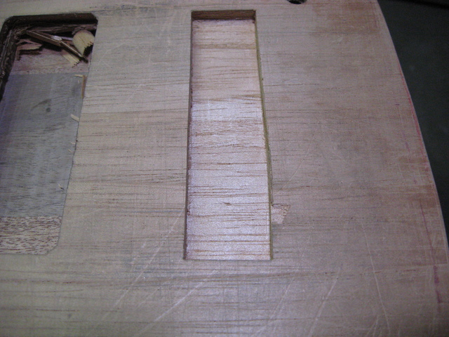
IMG_7444.resized.JPG


I found the chip and glued it back in. I didn’t do a good job. This picture makes the repair look better than it is. Once hit with finish, the repair became much more visible. Exactly the opposite of what I was hoping for! Fortunately it will be kind of hidden being so close to the bridge.
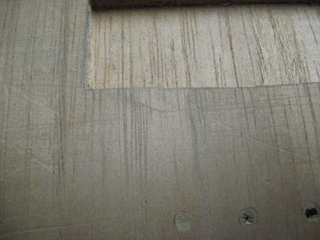
IMG_7461.resized.JPG


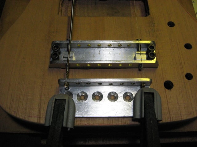
I was going to use a bar tailpiece (as is common with these types of bridges) but I ran out of room on the side due to the control cavity routing. I decided to use a tailpiece I made (but didn’t use as it was too low) from build #2. Don’t worry about how bad it looks, I will hide it using a methoed I used in build #3.

Lining things up.
IMG_7452.resized.JPG


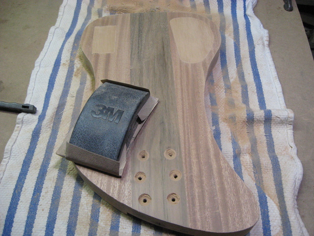
And now … lots of sanding in preparation for finishing with Watco Danish oil
IMG_7463.resized.JPG
 
I made knobs out of the body wood cutoffs.
IMG_7475.resized.JPG


One of these things is not like the other. Oops. Good thing I made more than I needed. Actually, I later made knobs out of the neck and fingerboard wood as I thought that would better visually tie the neck and the body together.
IMG_7480.resized.JPG


To clean up the knobs I used my poor mans lathe. This is the knob made from the body/fingerboard wood.
IMG_7496.resized.JPG


Drilling the hole to tap the set screw for the knobs.
IMG_7507.resized.JPG


I needed to sink the knobs down over the threaded part of the pots. This is the best idea I could come up with. It kind of worked, but not as well as I would have liked. I think my countersink has seen better days.
IMG_7508.resized.JPG


I don’t have any pictures of applying the finish. Besides on the neck, I also used Watco Danish oil for body. I do a longer process than what the instructions on the can say. Here is the back with the finish and the 9v cover unfinished. The cavity covers are made out of the same Spanish cedar that is on the face of the instrument. I was doing a final fitting of the covers (well I thought it was final) and counter syncing the screws at this point.
IMG_7503.resized.JPG
 
Now to design a cover plate to hide that pesky tailpiece. I picked #5 but it got altered later.
IMG_7513.resized.JPG


I needed to reduce the size of the tailpiece to work with the cover design I chose.
IMG_7517.resized.JPG


And here we go making the cover.
IMG_7521.resized.JPG


I finished the string ball end slots by hand. I knew the cover needed to be thicker and that is where the maple comes in to play (and to match the neck.)
IMG_7522.resized.JPG


Glue it together, cut out the form and start sanding.
IMG_7531.resized.JPG


After test fitting with bass strings, I needed to increase the size of the slots for the ball ends even more. I increased the size of all of them for a uniform look.
IMG_7533.resized.JPG


I didn’t like the design. It looked good by itself but it didn’t look good on the instrument.
IMG_7534.resized.JPG


Let’s cut it up and try and save it.
IMG_7535.resized.JPG


Nothing a little (or a lot) of filling and sanding can’t take care of.
IMG_7536.resized.JPG


The bottom view.
IMG_7538.resized.JPG


Some holes for screws to hold it in place and corresponding holes in the aluminum tailpiece (not shown.)
IMG_7540.resized.JPG


and I decided it was done.
IMG_7541.resized.JPG
 
Soups on! Putting Watco Danish oil on all the extra bits.
IMG_7543.resized.JPG


Electronics installed. Early on I though I would be able to get the battery in the control cavity but there was some poor planning on my part (possible interference with the bridge and or tailpiece) that resulted in that not being possible. Glad I caught it in time. Such are the difficulties of working with a small body. Anyway, that is the reason for the strange looking control cavity.
IMG_7575.resized.JPG


Even though I measured and test fit the covers previously, now there were clearance problems. Why? I didn’t have the patience to do this correctly so I ended up with this on the inside of the covers. I can always go back and fix it (yeah, right.) If you want to know what the opposite of “attention to detail” is, well here is the answer in picture format. The picture is before reapplying the Danish oil.
IMG_7578.resized.JPG


The tailpiece installed.
IMG_7579.resized.JPG


With the cover just set in place for the picture. See how the chip repair sticks out now that the finish is on it? :(
IMG_7581.resized.JPG
 
Everything else was assembled. I leveled and crowned the frets.
IMG_7565.resized.JPG


The truss rod adjustment hole was too small. I had to make it bigger, but unfortunately now it doesn’t look as good as it originally did. For easy and often access I don’t like having a truss rod cover. The vertical line is a crack in the veneer. All 3 of my instrument with headstocks have that same crack and it wasn’t planned. I am just glad that they are all straight, clean and in the center.
IMG_7599.resized.JPG


Final item was the installation of the 2 Hennessey strap locks. I like them, but I may replace them with Dunlop flush mounts just due to their locations (especially the one on the back that doesn’t allow the instrument to lay flat.) I've never had strap locks before on any instrument I've owned, but I feel this type of design requires them.
IMG_7584.resized.JPG


Installing the strap locks and putting the instrument on for the very first time was the moment of truth. Would the instrument sit well, balance (in all directions) and the strap not be in the way of playing with these strap button locations? The big unknown from the very first day I started planning would be revealed. So many design decisions were based off of those strap button locations. I was actually shaking as I drilled the holes. I was extremely happy that the answer to that big question was a big yes on all counts. What a relief!
IMG_7590.resized.JPG


Finally, in the next part I’ll have the finished pictures (and they’ll be bigger than these that I made smaller for easier perusing) ... and thanks to those that stuck with me and followed my story.
 
Wow. I found this from the link you gave to your YT channel, then from the Roberta Flack video back to here.
I have long wanted an NS Stick but with exchange, duties and shipping it's a lot of money so I'd like to make one. This thread was really inspiring and I think it might be in the future, if I can convince my business partner to put some time into doing the CAD work for the bridge and the time on the CNC to make it.
I'm sure I'll revisit this in the future to ask questions.
 
  • Like
Reactions: rwkeating

Latest posts