• TalkBass has been independent since 1998. Add your voice.
    Create a free account to reply to discussions, view embedded media, and browse with fewer display ads.
    Join freeLog in
    Want zero display ads or expanded classifieds tools? Compare plans.

Building A CNC - Watch a first timer stumble through a crazy build

While the ideas of how to mount the ball screws percolates in my head, there were still a few tasks to be done.

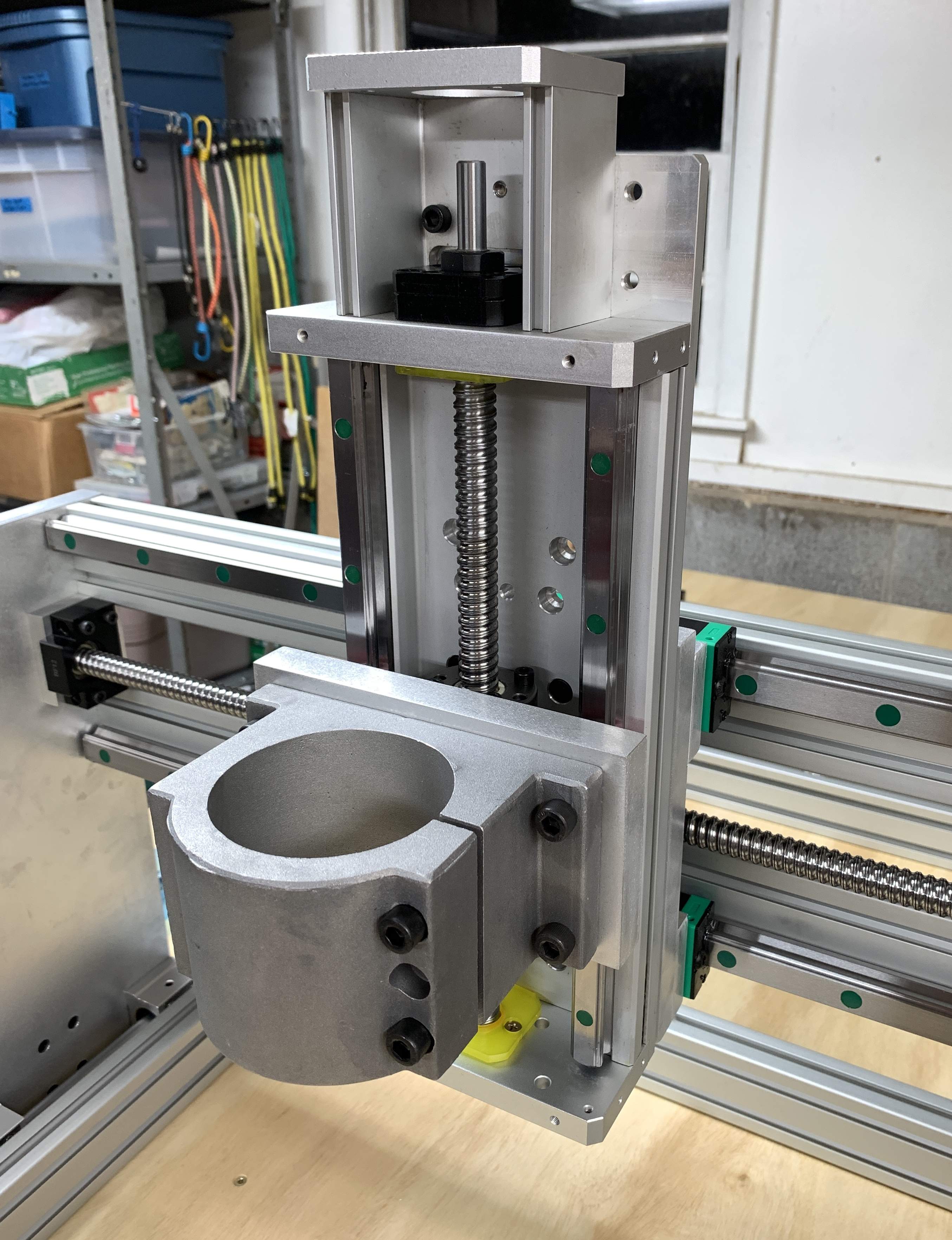
How about mounting up the Z Axis slider??

IMG_1532.JPG


IMG_1535.JPG


IMG_1531.JPG


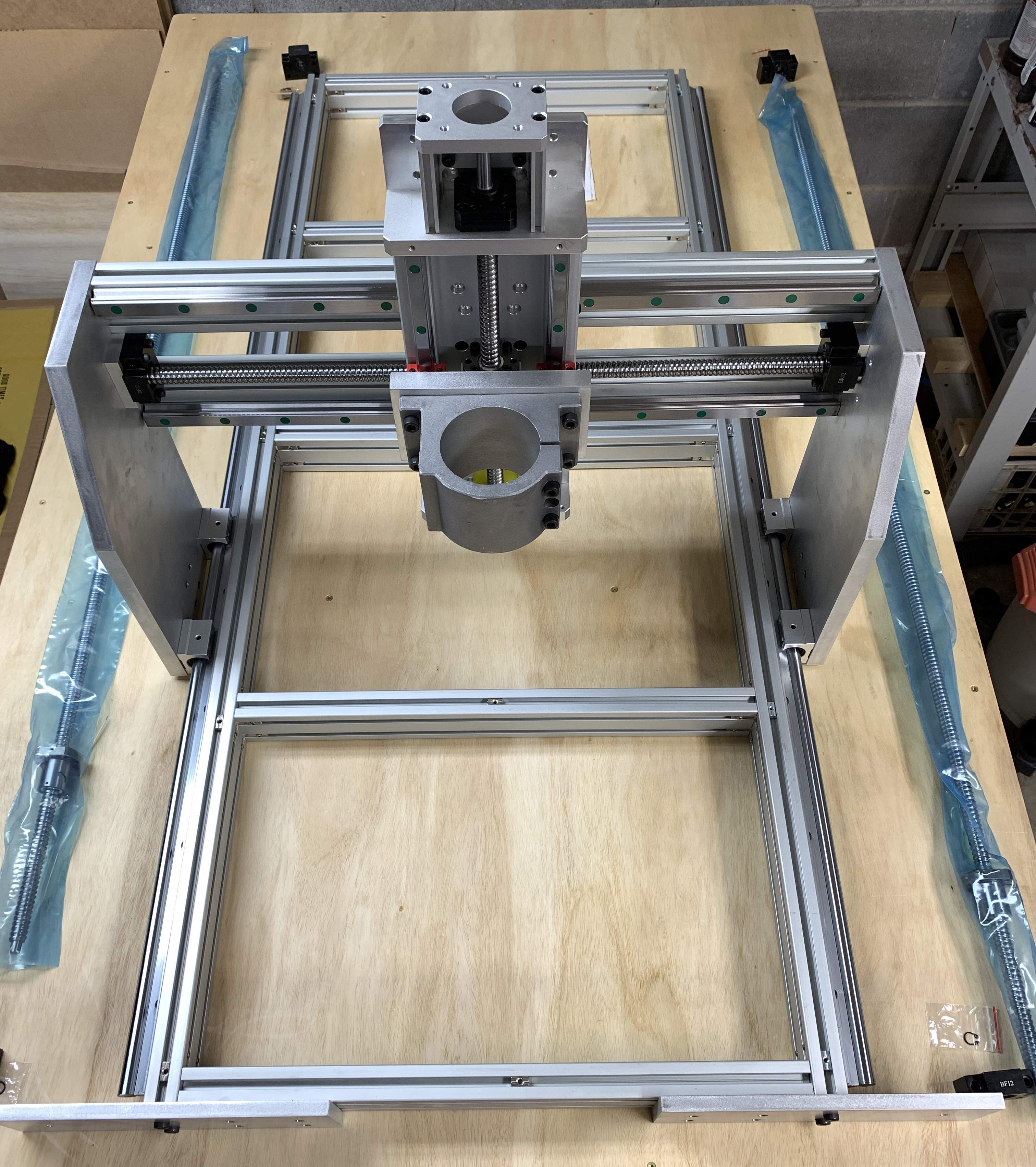
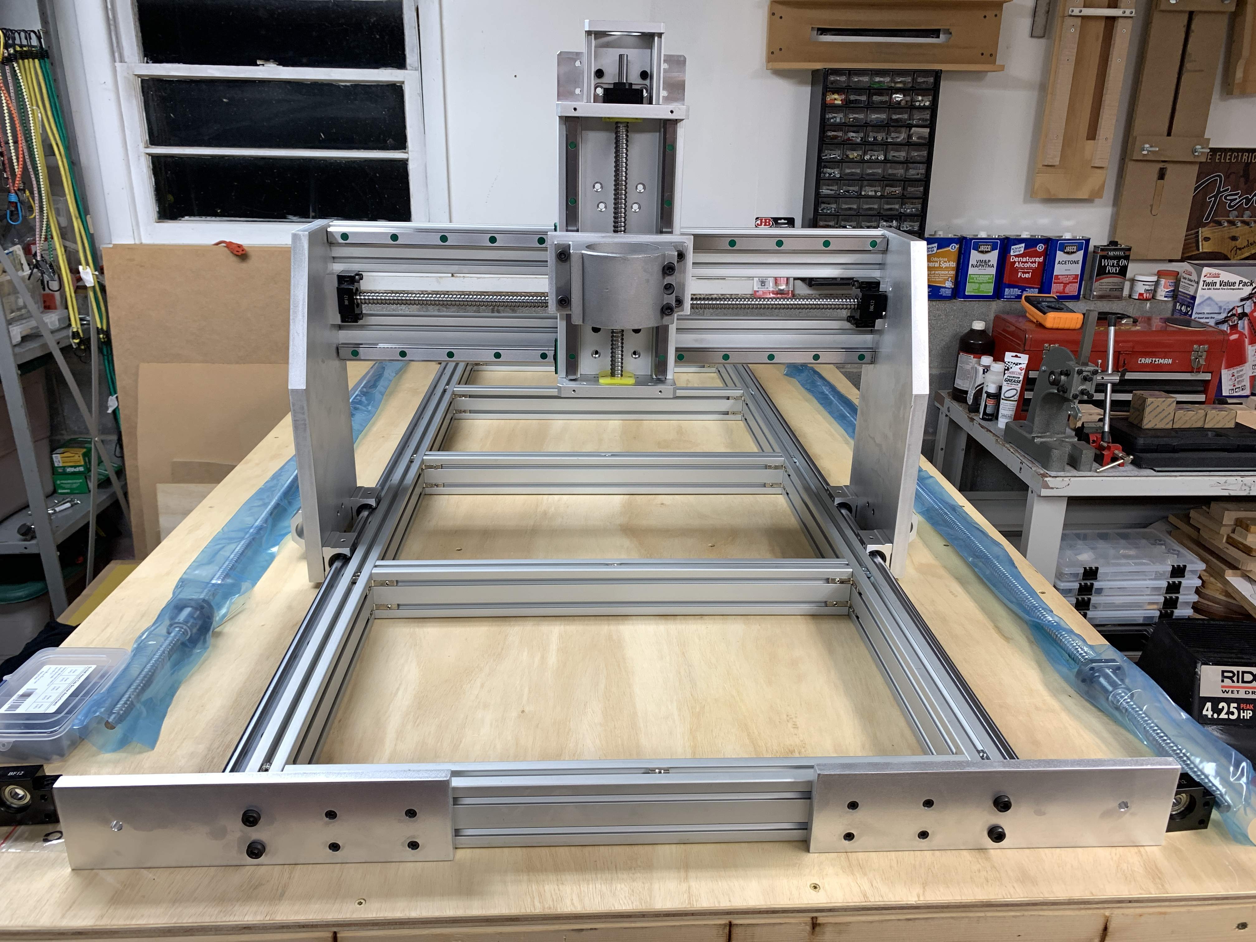
Of course, a video was recorded of the gantry being moved from the front to the back! It moves smoothly and stays square!


I’m off to the garage to do some more work…..
 
Of course because this CNC is being built from scratch and not from a kit, not even following the plans I purchased, because along the way, many upgrades were made. The plans called for lead screws (I’m using ball screws), all round linear rails (two of my Axis’s use flat rails) and used plywood (mine is aluminum).

If you’ve been following along, this build has drifted really far from the plans.

Which means that in many cases extra brackets, stand offs and more needs to be manufactured.

So after a great deal of measuring and consideration, a bunch of brackets were “designed”. These all have to be cut out of Aluminum. Then drilled, tapped and scuffed.

Here are the designs I came up with.

IMG_1549.jpg


IMG_1550.jpg


IMG_1551.jpg


One area that needed attention was stops for the gantry… the liner rails are about 50 mm short of the length of the base, so stops are required, just in case, so the seal, or worse yet the bearings in the blocks do not go past the end of the rails.

The ball screws are short as well, so a stand off was designed to hold the bearing blocks and in the front the stops have been incorporated into the single design.

Sure, the design of this CNC will have proximity sensors, so the hard parts should never touch or crash into each other, but this is just for safety and to protect the bearing blocks from internal damage.

Also needed to create brackets to hold the drag chains on the Y and X Axis’. It’s possible that an additional drag chain will be required for the Z Axis, but can’t design anything until everything else is in place and I can experiment with the wires and cooling tubes for the spindle.

There will be more to come!
 
Yes, I did some work on my brackets, but had to show off how OCD I can get…

During the course of the build, you will need to access a ton of parts, so digging through boxes and bags every time you need a part. The worst is you may not find what you need, or worse, miss it and have to stop to go out and buy more and discovering you had more than enough for your build.

Yes, I have far more than enough parts for this build and will definitely have a bunch of stuff left over at the end.

Here is the result of just some of my OCD…

IMG_1631.jpg


IMG_1630.jpg


The empty spots are the ones that are used most, so more are on order.

IMG_1633.JPG


IMG_1634.JPG


IMG_1632.JPG


Now that you’ve had a good laugh….

…. Onwards!
 
I've got all sorts of those little compartment boxes filled with bits and bobs to help stay organized, but no labels... however we do have one of those label makers at work, so now I'm thinking about picking up some label tapes and making a list. :D

Hey @Beej originally it was only masking tape and a sharpie... since the CNC Controller needs to be labeled, I purchased a Label Marker... there's all kinds of stuff we can label and everyone will be able to read them!!
 
  • Like
Reactions: TerribleTim68
It’s time to build the brackets….

Having “designed” the brackets for the ball screws and stops really helped a great deal. First step was to cut the aluminum… after thinking about it for a while, I had the idea of using some clamps on my sled so the small pieces could be held steady and keep fingers far away from the blade.

It was a quick and dirty job, so the clamp brackets look a bit rough… but it works great.

IMG_1608.JPG


Using this clamp bracket, it was easy to cut through a 3/8” bar of aluminum with one pass, having to use the “peck” method… it also requires using the shop vac after every single cut as the aluminum chips fly all over the place, including on me!

Here is what the aluminum edge looks like right after cutting…

IMG_1609.JPG


But I like to sand the edges so they are cleaner.

IMG_1610.JPG


Also sand the flat edges smooth as well.

IMG_1612.JPG


Then it was time to drill all the screw holes.

IMG_1613.JPG


And of course all of the holes were slightly counter sunk and then tapped….

IMG_1614.JPG


IMG_1615.JPG


Of course the pieces had to be laid out on the drawings, just to show off!! LOL Then assembled….

IMG_1636.JPG


IMG_1637.JPG


IMG_1638.JPG
 
Wow, very clean, precise work, you shoulda been a Machinist! I've always been fascinated by metal work, but never had the opportunity to do much of it. The relative softness of aluminum makes it possible to do a lot of it with woodworking tools, but a machinists lathe or end-mill would make short work of it.

Even better if you have a CNC you can make all kinds of stuff with wood, plastic or aluminum!!

But for now I struggle along with woodworking tools and a bunch of hard hand work.
 
  • Like
Reactions: Gilmourisgod
Once the ball screw bracket was assembled and the bearing block attached, it was time to hook up the ball screw.

IMG_1591.jpg


IMG_1593.jpg


Unfortunately when the ball screw was connected, there was quite a bit of binding! Crap!! In an attempt to figure out where the binding was occurring , I used some wedges to lift the frame. Discovering that no matter how much you plan, measure and even test, stuff happens!

IMG_1595.jpg


IMG_1597.jpg


These photos show the issue. Unfortunately when the new position would not allow the mounting plate to be re-used, a new one was manufactured. Next the bearing block was aligned, marked, drilled, tapped and finally bolted together. Now working smoothly, and easily.

Just an FYI, in the beginning the silly plan was to use hand cranks to move the gantry. After doing just that to move the gantry back and forth to test the smoothness and to ensure there is no binding, it took FOREVER to crank it from one end of the rail to the other. It was a thought that would have been very impractical in practice.

IMG_1617.JPG


IMG_1618.JPG


IMG_1620.JPG


You can see the mounting bracket performs double duty as a stop for the gantry.

IMG_1623.JPG


When I bolted up the rear bearing block, the ball screw was very straight. Again when design meets the real world, the block had to be rotated 90 degrees because the gantry stop got in the way. So now the end bracket looks like Swiss cheese….

So new Aluminum bars were ordered and the rear Y Axis brackets will be re-made and then replaced. Sure, they could be used, but the extra holes just bother me!!

IMG_1602.jpg


IMG_1603.jpg


Next up is to make the bracket for the other side and bolt up the other ball screw… at some point I need to make protective covers to protect the ball screws from dust and debris. It must be easy enough to remove, so the ball screw can be cleaned, lubricated and properly maintained.
 
Last edited: