• TalkBass has been independent since 1998. Add your voice.
    Create a free account to reply to discussions, view embedded media, and browse with fewer display ads.
    Join freeLog in
    Want zero display ads or expanded classifieds tools? Compare plans.

Building A Short Scale P Bass

The details for the brass bridge are provided on the PDF sheet included in the opening post. The dimensions are specific to this instrument, but it's quite easy to adapt for any number of strings or specific spacing.

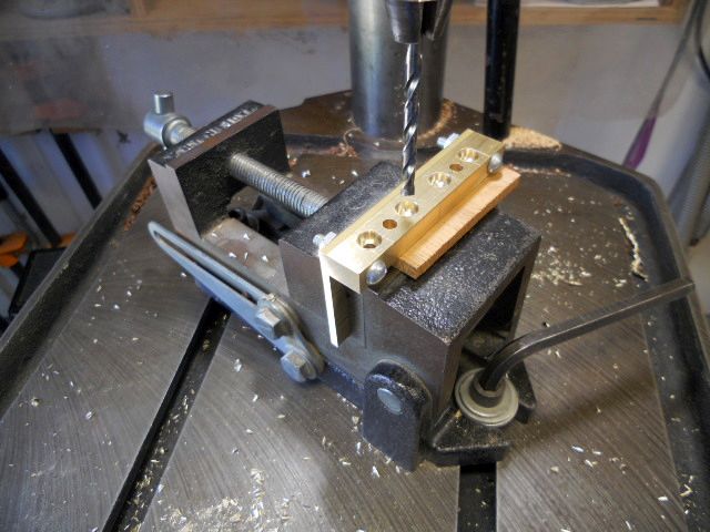
Here the 3/16" holes and 5/16" recesses for string ball ends are being machined into the rear brass bar. The 3/16" holes for the intonation adjustment screws are also drilled. The bar has been temporarily bolted to the base plate so it can be more easily held in the drill press vise. I started with 1/2" tall bar stock because it's what was on hand, but I'll later reduce the height to 3/8". Doing it this way lets me easily drill the holes and sand away the excess material so the holes will be close to the edges without risking the 5/16" recesses being too close to the top or bottom edges when they are drilled.
2DsBh7R.jpg


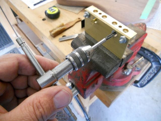
I drill, countersink, and tap for two short #8-32 brass flat head screws to hold the two pieces together. With the two #8-32 screws installed the temporary screws at the ends can now be removed. The end holes will be used for two of the four #10 stainless oval head screws which mount the bridge to the body.
5UoDknu.jpg


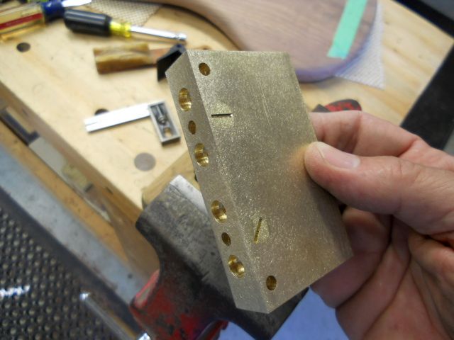
With the flat head screws secured the bottom and back edges can be sanded using the 4" sanding belt and the small 6" 150 grit disk on my combination belt-disk sander.

I disassembled the string bar from the base and shortened it to 3/8" in height just after this photo was shot and then reassembled for final shaping. This allowed me to get as close as possible to the 5/16" string ball counterbores.

The edges and corners of the bridge are rounded with the 150 grit 6" disk of the combination disk / belt sander. The initial rounding is followed by refining the shape with a 5" random orbit sander with a 220 grit disk.

This photo was taken just before rounding of the top edges, with the surfaces smoothed up with the 220 disk and 5" random orbit sander.

The two 3/16" mounting holes located 5/8" back from the front edge of the base plate were also drilled and all four of the mounting holes countersunk to match the heads of the stainless steel #10 oval head mounting screws.
hdUWTQV.jpg
 
Last edited:
The brass pieces which form the string barrels are cut to length, drilled, tapped, and rounded. The tapped intonation adjustment hole is being used to hold the brass as it is sanded to shape. The ends of the string barrels are also rounded and sanded to a visually pleasing shape.

cbAx9Kp.jpg


The brass bridge components are finished up by hand sanding with 320 grit to remove any remaining marks left from the orbital sander and to round the edges a bit. A final step is spending an hour in the play sand in my vibratory tumbler for a nice soft satin finish.

7mPWENL.jpg


The brass bridge parts are swirled in a patina finishing solution to give them a final antiqued finish. They were in the solution about 30 seconds here, longer times will produce darker final finish. The solution is returned to the bottle after use, it can be re-used many times, so don't discard it!

The bridge is assembled here with the exception of adding the four #8-32 socket head height adjustment screws. Suitable springs are easily found at the local "Springs Are Us" store (Ace Hardware in my case...). If the helpful hardware person gets inquisitive just tell them it's part of the push button transmission speed selector in your 56 DeSoto.

As a final note, it would be easier and require less precise centering of the rear mounting screws if the string retainer bar were made to 1/2" width. That would make it easier to countersink the top area without the screw heads coming up to the edges of the brass. A new design always helps to bring out better ways to handle the small details in the future, I’ll be sure to remember that for the next one. (Yeah, right... !)

The bridge will be attached using two #10 x 1-1/2" stainless steel oval head screws at the back and two #10 x 1-1/4" stainless steel flat head screws in the holes in the base plate under the saddles. I would normally use a third screw in the string bar centered between the second and third strings but didn't here because it would be directly in line with the joined edges of the body halves.

Normally I would also add a mounting screw in the center of the rear bar but chose not to use a center mounting screw because the body is joined at the center. The glued joint is very strong, but it's a matter of principle for me not to introduce unnecessary stress in the joint by adding the wedging action of a screw.

HyTjkkS.jpg


I'll trim the #8 intonation screws a bit shorter after the bass is assembled "in the white" to see where the saddles will eventually end up.

Not too shabby, eh?
 
Last edited:
I inserted three 1/4" x 20 pointed screws in the neck tee nuts to transfer their positions to the neck pocket. I drilled the remaining three 17/64" holes in the neck pocket and attached the neck with 1/4" x 20 furniture bolts cut to 1-1/2" length.

7Gr8WX6.jpg


The furniture bolts have a low profile head and aren't much thicker than a back plate, so they could be left proud of the surface if desired. I much prefer to have neck mount bolt heads flush to the surface, though.

EyWSXAV.jpg


I recess the furniture bolt heads by using a hardwood block bored with a 3/4" Forstner bit clamped against the body to align the counterbore over the drilled hole. (I marked around the furniture bolt head with a pencil before removing them.) The alignment block being held has a 3/8" slot cut in it for the Forstner bit shank and is cut to a length that ensures the counterbore will be exactly 1/8" deep.

8u4FRLy.jpg


Here are the furniture bolts snugged down in the counterbored top.

yCzekJT.jpg
 
The truss rod access is routed at the end of the neck pocket with a 1/2" core box bit with a 1/2" bearing added to the bit shank.

KYWFDEX.jpg


Using one of my favorite tools, the 5" random orbit sander fitted with 220 grit disc and controlled with a momentary action foot switch. It takes about 10 minutes to go from rasped surface to final neck profile using this extremely controllable tool.

NEVFi2b.jpg
 
I really like the convenience of using furniture bolts too. :D Off the shelf and I can include one of those little Ikea hex key wrenches for kitsch value. Fun fact, the truss rods I've been using lately also fit those little hex keys, so it's a win-win.

One thing that bugged me was that I had to drill a slightly oversized hole with my forstner to fit the furniture bolts, because I don't have a full set of metric-sized forstners and I'm cheap. What I started doing was turning the head of the bolt down by throwing it in a drill chuck and running a file against the edge. This lets me drill a hole that fits nearly snugly for a clean look.
Since I mostly paint my hardware, it's been workable. I'm planning to use chrome ones for my WBO2021 entry, so I think I may break down and order the metric forstner. :D
 
I really like the convenience of using furniture bolts too. :D Off the shelf and I can include one of those little Ikea hex key wrenches for kitsch value. Fun fact, the truss rods I've been using lately also fit those little hex keys, so it's a win-win.

One thing that bugged me was that I had to drill a slightly oversized hole with my forstner to fit the furniture bolts, because I don't have a full set of metric-sized forstners and I'm cheap. What I started doing was turning the head of the bolt down by throwing it in a drill chuck and running a file against the edge. This lets me drill a hole that fits nearly snugly for a clean look.
Since I mostly paint my hardware, it's been workable. I'm planning to use chrome ones for my WBO2021 entry, so I think I may break down and order the metric forstner. :D

Good ideas!

In my case I like the slightly oversized counterbores as it makes alignment easier and makes it easier to assure that the end of the neck jams up tight to the end of the neck pocket, which I think may contribute to coupling the string energy to the body. I'd like to think it does, anyhow. :)

The furniture bolts come in a variety of finishes, so I'd prefer to not take off any of the factory finish which I'd never be able to match. once you knock down the counterbore edges with a bit of sanding they end up looking a bit better and have a smooth feel to the edges.
 
Last edited:
“Oh no! He's going to use the Safe-T-Planer AGAIN!”

Yes, it's true... Here it's used to clean up both sides of the pickup routing jig made by gluing 1-1/8" wide strips together. I think I previously mentioned my frugal nature, or another way of putting it, being too cheap to buy a fancy pre-made routing template …

The pair of pickup covers was taped together to lay out the size of the opening so there was 1/16" clearance around the covers.

qbwz7I6.jpg


The position of the opening was drawn on painter's tape to verify pole piece centering under the string paths. I wanted to make absolutely sure they ended up where I wanted them. The bridge is temporarily attached with two #8 by 1" screws through the bridge base plate.

Seeing the relationship of the components I decided at this point that the bridge was a little taller than what I really wanted it to be. I removed the bridge, disassembled it, and reduced the rear string anchor bar by sanding 1/16" off the top and bottom of the bar. It was reassembled, the rear corners sanded, and the top screw holes countersunk deeper. A bit more quality time in the vibratory polisher play sand and a quick bath in the patina solution made it better than new.

53TYIXX.jpg


The small amount of extra time was worth the effort. I'm much happier with the shorter overall height. The LaBella Black Tape Short Scale first string is fed through the bridge here to check that the string length works well on this new design.

K0PdKXR.jpg


Pulling the string up to the first string tuner string post verified that the purple string silk cleared the nut and was 3/4" from the string post. This is ideal, so I can sleep well tonight knowing everything fits as planned. It's always better to know you've created firewood early in the game before putting additional work into something that doesn't meet your expectations!

e7ueWq6.jpg
 
The pickup routing template is secured to the body with heavy duty double-faced carpet tape and the six outside corners are drilled with a 1/8" drill bit to a depth of 3/4".

ysSBHXK.jpg


I drilled four 1" diameter holes with a Forstner bit to remove the majority of the waste material before pattern routing the pickup opening.

9wEnOCu.jpg


After pattern routing the pick up openings with a 1/2" router bit with a shank mounted bearing there is a small area between the routed edges and the 1/8" corner holes that needs to be pared away with a flat chisel. This is done carefully to make sure the opening looks good when it's done.

CBEre40.jpg


Switching to a 1/2" bit with an end-mounted bearing, the router it is used to open up the previously bored control cavity holes from the back. These were bored before the mating body halves were glued together, so it pays to do all of your work carefully so everything mates up, as in this example.

gWxk3WR.jpg
 
A protective plate is taped in place over the routed pickup opening to drill the angled hole for the pickup wire. This is a 8" long 1/4" bit that's easy to lay down at an angle to intersect with the volume control area of the control cavity. At this point you really don’t want to see the tip of your bit poke through the pristine expanse of the rear body surface!

AHBtwPD.jpg


Tape is used to mark where the bridge will be positioned so the angled hole for the bridge grounding wire can be drilled to meet the output jack area of the control cavity. Location isn’t critical, but I make sure the wire ends up where the bridge mounting screw will draw down tightly against it, pulling it into the wood surface.

CxRMzbJ.jpg


The pickup mounting ear tabs are marked with a pencil and the wood removed with a 3/8" drum in the rotary tool. Lots of different methods to do this, I’m showing my one-off method since I don’t do many P bass pickup installs.

GPtsUV9.jpg


The Dunlop Straplok ferrules are mounted by drilling 7/16" deep holes with a 3/8" Forstner bit. The screw hole is drilled with a 7/64" bit and the screw lubricated with Beeswax and installed temporarily. This one is about an inch above the rear center line and the other one is added at the upper horn's tip.

0pMASN9.jpg
 
The control cavity and cover will get a bit of attention next.

The process of routing the control cavity lip and making the matching cover will require a bit of thought to follow, but it’s worth taking the time to grasp it. This is a methodology that can be adapted to many instrument building tasks. As an example of the technique's usefulness, I use a version of the method to cut the slots for tuners in my slotted headstock instruments.

The basic idea is to use an over-sized guide that the router base rides against. This method is far better (at least for me!) than using guide bushings. The routed shapes are somewhat limited by the router base diameter, but it’s useful in many situations that pop up in instrument construction.

The control cavity cover routing guide is made by drawing an opening that allows the router base to cut a precisely shaped recess in the guitar body using a 1/2" bit.

This photo shows the outer guide ring clamped over thin plywood and the cover shape routed through the plywood by using the outer ring as a guide for the round router base. The outer guide is made by cutting and sanding the opening to create the desired final cover shape. It's not difficult to work with a specific bit diameter and router base diameter to figure out how much larger than the desired shape the opening needs to be.

After the cover shape is routed out the outer guide shape is drawn on the thin plywood so it can be bandsawn and sanded to form the portion that drops in the outer guide section so it can be accurately positioned for use. That will become easier to understand in the following photos.

l64rGNB.jpg


Here is a photo of all three sections of the template and cover plate jig. Notice the center section, made by drawing the shape on birch plywood and cutting and sanding so it fits the middle section precisely. This is used to pattern route the actual cover.

Som1NWn.jpg


Here the cover is made from alternating 1/16" layers of walnut veneer. Glue is applied to the center layer, assembled in order, and clamped. Veneer layers on left, veneers under clamping pressure (center), and completed "plywood" cover material at right.

iI2tXoX.jpg


Cover material is attached to the routing guide with double-faced carpet tape and cut just outside the guide to remove the majority of the material.

BPI261E.jpg


A bearing guided 1/2" router bit is used to flush trim the cover plate to the guide profile.

fUrYyn8.jpg


The control cover outline is routed in a piece of scrap material to test the fit before committing to routing the actual bass body.

TBt2hHT.jpg


The center layer is placed within the outer guide to locate the exact position where the cover recess will be located. The outer guide is clamped to the bass body. I then lift the center layer out and route the body to create the control cavity recessed lip.

Ls6qP4B.jpg


After the body is routed the cover fit can be checked. This one will be ideal after the edges are sanded lightly. The grain mismatch won't be so apparent once finish is applied.

If a "near perfect match" is desired then the wood removed from the waist area could be used to make the outer 1/16" veneer layer of the control cover.

I would have actually needed to think ahead to do that. :)

NDA67le.jpg
 
Last edited:
Control knobs, anyone?

I chose to make a couple of control knobs, so small pieces of olive wood that I had in the scrap pile were glued on sacrificial backs and turned on the lathe. I'm really "frugal" so my most often used turning tools are made from cheap large pry bars fitted with carbide shapes from Arizona Carbide. The carbide tip is 1/2" diameter, so it conveniently made the 1/4" radius relief cut for the top of the knob. The knobs were pre-finished by polishing them with 220 sandpaper, 0000 steel wool, and a final bit of shining up with beeswax and a small scrap of cloth.

ogFs46u.jpg


The knobs were bandsawn off the backing plate and held in a temporary clamping board so they could be counterbored to fit over the potentiometer nut and drilled to hold the epoxied in brass insert that was removed from a couple of extra plastic knobs I had on hand.

I chose to drill the set screw hole with a #29 drill bit and tap the wood knob and brass insert for a #8-32 by 5/16" long Allen head set screw. The guide hole used to locate and drill the set screw hole while the knob is held securely is visible in the block that holds the knob.

If you look closely you can see the #29 hole drilled in the side of the knob that houses the Allen head set screw that is used to secure the knob on the solid shaft potentiometer.

The dowel rod in the drill press chuck was used to push the insert squarely into the hole which was drilled to house it. The hole was sized to be a very easy press fit for the brass bushing and epoxy was used to line the hole to retain the bushing securely.

noYIUyh.jpg
 
Last edited:
Control knobs, anyone?

I chose to make a couple of control knobs, so small pieces of olive wood that I had in the scrap pile were glued on sacrificial backs and turned on the lathe. I'm really "frugal" so my most often used turning tools are made from cheap large pry bars fitted with carbide shapes from Arizona Carbide. The carbide tip is 1/2" diameter, so it conveniently made the 1/4" radius relief cut for the top of the knob. The knobs were pre-finished by polishing them with 220 sandpaper, 0000 steel wool, and a final bit of shining up with beeswax and a small scrap of cloth.

View attachment 4064629

The knobs were bandsawn off the backing plate and held in a temporary clamping board so they could be counterbored to fit over the potentiometer nut and drilled to hold the epoxied in brass insert that was removed from a couple of extra plastic knobs I had on hand.

I chose to drill the set screw hole with a #29 drill bit and tap the wood knob and brass insert for a #8-32 by 5/16" long Allen head set screw. The guide hole used to locate and drill the set screw hole while the knob is held securely is visible in the block that holds the knob.

If you look closely you can see the #29 hole drilled in the side of the knob that houses the Allen head set screw that is used to secure the knob on the solid shaft potentiometer.

The dowel rod in the drill press chuck was used to push the insert squarely into the hole which was drilled to house it. The hole was sized to be a very easy press fit for the brass bushing and epoxy was used to line the hole to retain the bushing securely.

View attachment 4064630


Would you mind posting some details on the shop made turning tools? I’m very interested in different shapes for knobs. Thanks!
 
Would you mind posting some details on the shop made turning tools? I’m very interested in different shapes for knobs. Thanks!

Not much to say detail-wise.

The carbide cutters are available in a few standard shapes and come with a new screw to fit the conical shape of the attachment.

I make a holder for them out of cheap pry bars. The end of the bar is first heated cherry red to anneal it, cut off, shaped, tapped, and re-hardened by heating cherry red again and quenching in water.

Here's a closer view of one of my wood turning tools (technically scrapers, and not turning tools) with a close up of the business end. They work very well, and the cutters can be re-positioned or rotated for a new sharp edge when they finally get dull, which takes a LONG time!

3035-129431813122016.jpg
 
Not much to say detail-wise.

The carbide cutters are available in a few standard shapes and come with a new screw to fit the conical shape of the attachment.

I make a holder for them out of cheap pry bars. The end of the bar is first heated cherry red to anneal it, cut off, shaped, tapped, and re-hardened by heating cherry red again and quenching in water.

Here's a closer view of one of my wood turning tools (technically scrapers, and not turning tools) with a close up of the business end. They work very well, and the cutters can be re-positioned or rotated for a new sharp edge when they finally get dull, which takes a LONG time!

View attachment 4065278

Cool, thanks! Where do you get the pry bars? They look perfect for a turning tool handle. Will a propane torch work for the heating or does it need to be oxy-acetylene or MAPP gas?
 
Cool, thanks! Where do you get the pry bars? They look perfect for a turning tool handle. Will a propane torch work for the heating or does it need to be oxy-acetylene or MAPP gas?

I purchased 18" pry bars from Harbor Freight and Menard's. They are something in the neighborhood of 5 bucks.

A propane torch will turn the end cherry red, no need for hotter sources.
 
  • Like
Reactions: Matt Liebenau
EVO fret wire is pre-cut to 1/4" wider than the fret board width for all fret locations.

RKvK8wV.jpg


A cheap Dremel "router base" is fitted to a scrap of 3/16" aluminum plate to make this "tang remover". The Dremel is fitted with two stacked cutoff disks and adjusted so the top of the disks are flush with the slotted plate. The wire is positioned in the slot and lowered down on top of the disks to remove the tang. The Dremel is controlled with the momentary foot switch shown in the photo. Each tang end is done by grinding off ½ of the tang then letting it cool a bit before finishing it off flush with the bottom of the fret crown. That keeps the EVO wire from getting too hot and saves fingers from getting burned in the process. It's actually a quick n' easy process.

I undercut one end of all the frets then place each fret over its corresponding slot and trim the length so approximately 1/8" hangs over each side. I then use the tang remover to finish up the end that was just cut. This is done so the tang stops short of the fretboard slot end. The small recessed area left below the fret crown is filled after the frets are installed.

dNCcrMF.jpg


The fret slots are slightly beveled to relieve the shrp edge at the top of the tang slot. Always a good practice when fretting, it's mandatory when EVO or stainless steel fret wire is used because the inner corner at the top of the fret tang isn't a sharp 90 degrees because the wire drawing process leaves a slight rounding at the inner corners. The slot beveling ensures the fret crown fits down against the board.

hkiiVq7.jpg


A tiny bead of Titebond Original is used, mostly to lubricate the fret tang as it is driven into the slot. (Bottle available from Rockler...) It also assists in keeping the fret locked in place. I do 3 or 4 slots and then drive those frets in before moving on to the next 3 or 4 frets. The neck is placed over a shot-filled bag to prevent any damage to the neck and provide a firm and bounce-free surface so the hammer taps can work effectively.

mvbP2zs.jpg


I clamp the frets down against a cork padded surface for the remainder of the day.

Ta5kmoZ.jpg


The slight overhang of each fret is trimmed off using a cut-off wheel in the Dremel. This takes about a half-second to trim each fret overhang and they are done at an angle to make it easy to get close without accidentally contacting the fret board edge. Again, the momentary foot switch is used to control the Dremel.

hBy2kZH.jpg


The boring yada, yada, yada fretting stuff, not shown so it doesn't put you to sleep...

The fret ends are finished flush with the board and each slot has a couple of small drops of CA applied over the slot. This runs into the slot to further lock the frets in place and helps to fill any void between the fret tang and the remaining slot depth. This is followed with lightly sanding the neck edge to pack the slots with wood dust and applying a drop of CA over the slot end. File and sand when dry to complete the fret installation.

That's all I got to say for today. :)
 
White ABS rod in 1/16" diameter is added to the side of the neck. I added the same marker material to the top of the wood knobs while adding the neck side markers. The tip of the rod can be dipped in Original Titebond or a small drop of CA glue before pushing the rod in the bored hole. The rod is cut off slightly above the surface and sanded flush after the glue has dried.

cKuviAF.jpg


Areas between the previously bored control cavity holes are connected with the router, leaving a rib of material between them. Not necessary, but it does add strength. The area where the potentiometer connections will reside is also enlarged.

Jr7PfBd.jpg


The pickups are prepared for mounting, the brass backing plate is re-sized slightly to fit the opening. I drilled the pickup mounting holes 3/32" and used black screws that are normally used to mount P-90 pickups.

6zwp3ME.jpg


The 250K audio taper pots and output jack are temporarily fitted to a thin plywood template that holds them positioned exactly as they will be in the control cavity. This makes wire attachment super easy. The two .022 mfd caps will be replaced with a .047 mfd Orange Drop cap when permanently installed. The twin .022 mfd capacitors are sufficient for initial testing, and it’s what I have on hand.

Fj12kQc.jpg