
Enjoy the benefits of a premium membership!
Upgrade Account
-
TalkBass has been independent since 1998. Add your voice.
Create a free account to reply to discussions, view embedded media, and browse with fewer display ads.
Join free Log in
Want zero display ads or expanded classifieds tools? Compare plans.
You are using an out of date browser. It may not display this or other websites correctly.
You should upgrade or use an alternative browser.
You should upgrade or use an alternative browser.
Building an OM Bass
- Thread starter Dave Higham
- Start date
More options
Who Replied?

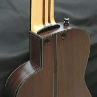
Although there was some ‘spring-back’ after bending, the sides were very flexible at this point, so it was easy to push them into the mould. The place where the jack socket will be installed needs to be beefed up so I shaped a piece of Spanish cedar to the appropriate profile and glued it in, again using epoxy. I think my profile was pretty good but epoxy is still best if any gap-filling is likely.
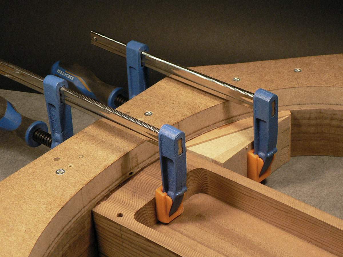
The junction of the jack support block and the centre block is a weak spot so I glued a triangular reinforcing block in there.
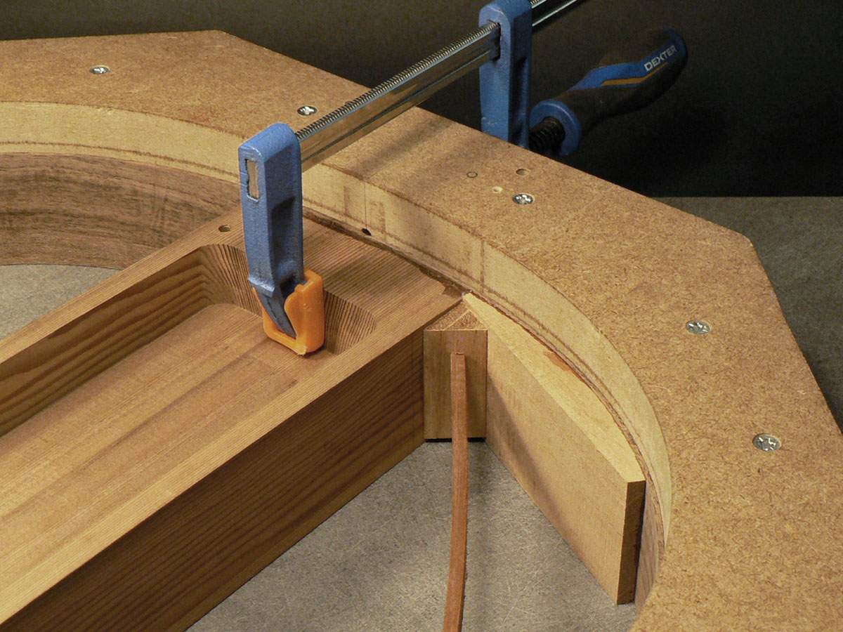
The junction of the jack support block and the centre block is a weak spot so I glued a triangular reinforcing block in there.
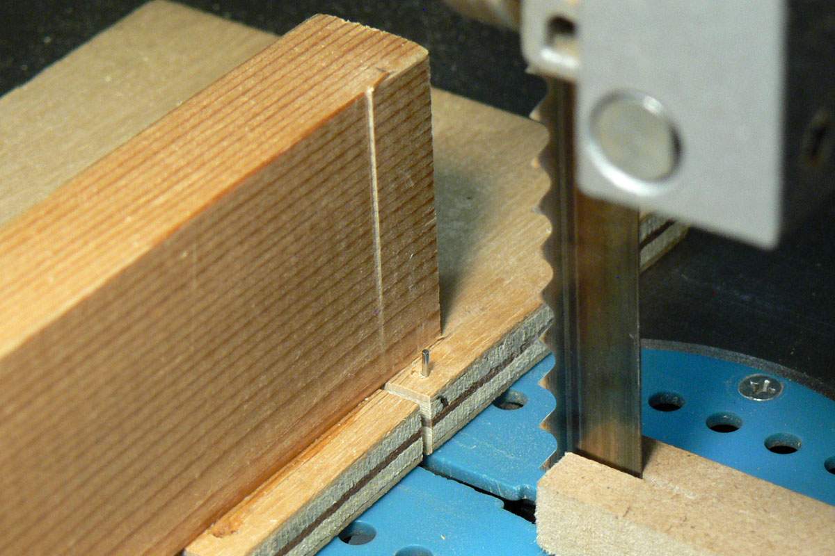
The sides need linings gluing onto them to increase the gluing surface for the front and back, so I have to make some. These will be kerfed linings, NOT ‘kerfings’. Kerfs are the sawcuts you make in them to make them flexible and kerfing is what you’re doing when you cut them. (Excuse the rant.) The kerfs are all cut on this piece but I put it back on the saw to show how they are made.
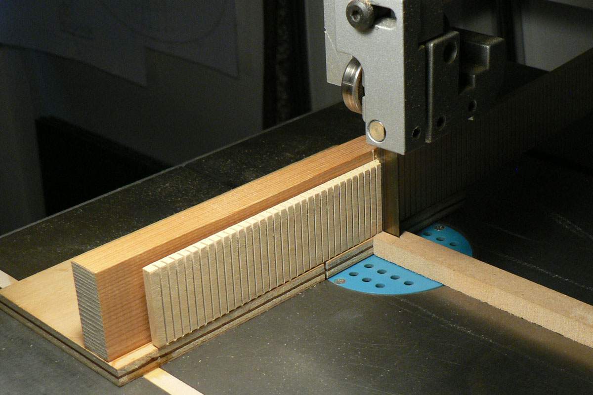
It’s a simple carriage that runs in a slot in the saw table and a stop clamped down to prevent sawing right through. You cut a kerf then move the wood over so the kerf drops onto the little pin and cut another one, etc., etc. The saw cut in the carriage is what happens if the stop comes loose and you cut the lining in two and swear a lot.
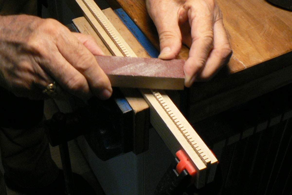
The piece of lining is cut into strips and one edge of the strip sanded smooth.
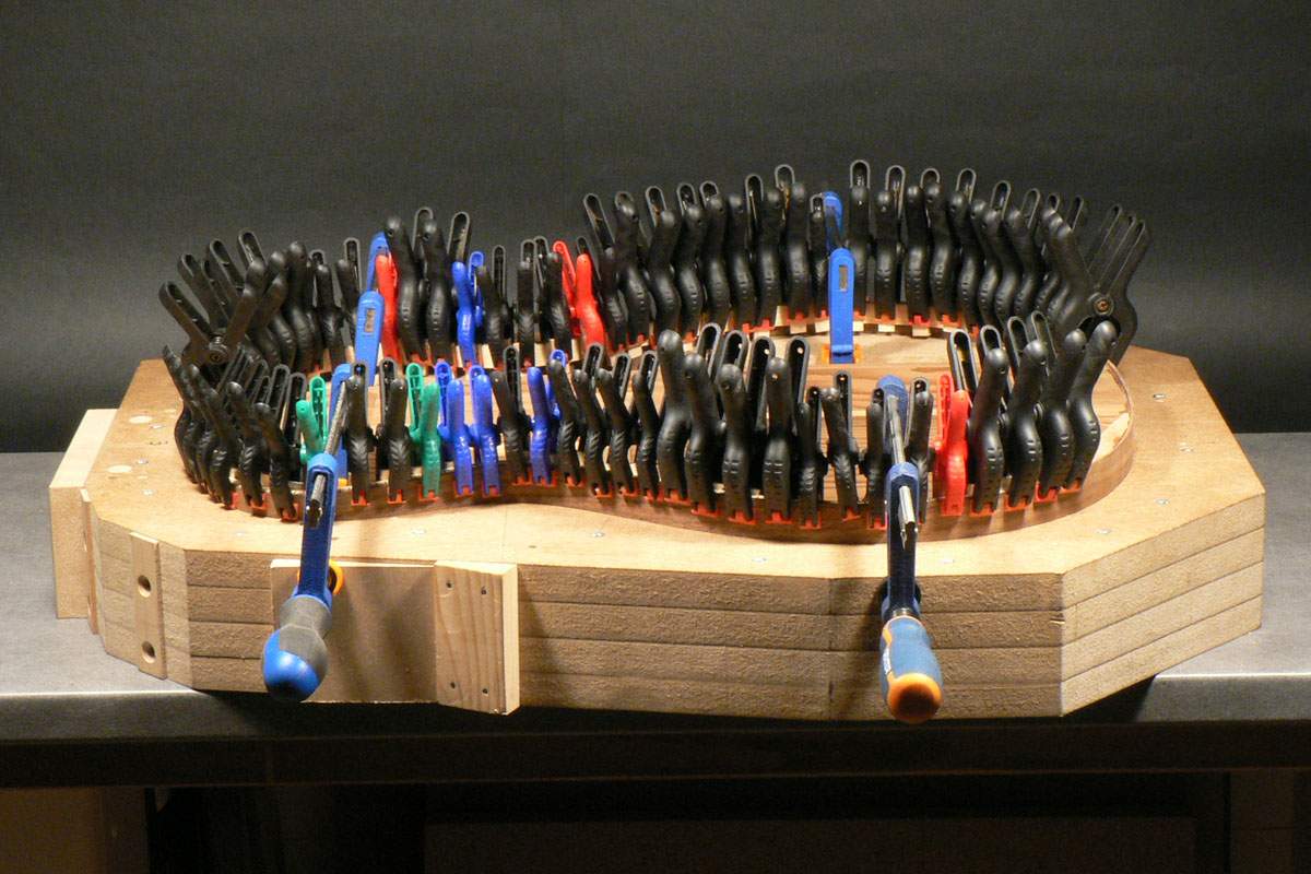
Gluing the linings to the sides with the traditional ‘forest of clamps’ photo. The lining are in there – honest.
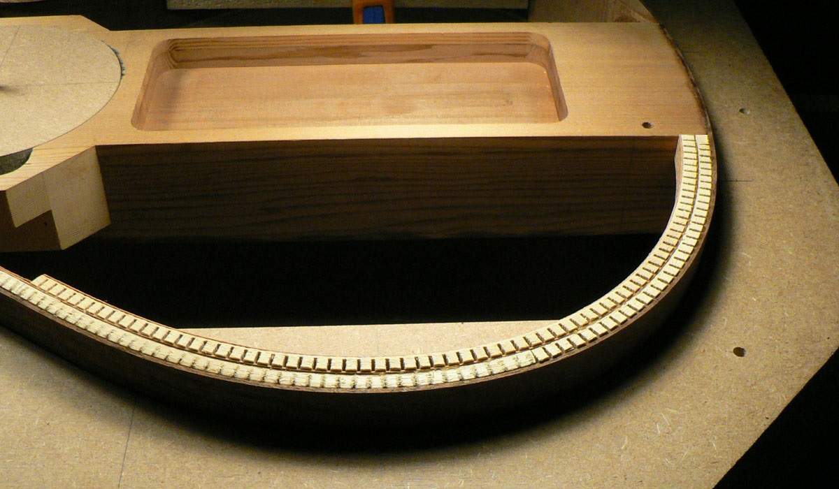
People used to glue the smooth side of the linings onto the sides. It seems the natural thing to do, but then someone thought of gluing the kerfed side and found that this made the sides a lot stiffer. I go one step further and glue the lining to the side and then add a couple of layers of veneer onto the lining. This means that the sides can then be taken out of the mould and they keep their shape perfectly. This is the front of the body so, in theory, the edge of the sides and the centre block are all in the same plane. The linings are glued in slightly proud of the sides so they can be sanded flush afterwards. The linings are doubled in this area as the plan is to make an arm bevel if everything works out as it should.
It’s a simple carriage that runs in a slot in the saw table and a stop clamped down to prevent sawing right through. You cut a kerf then move the wood over so the kerf drops onto the little pin and cut another one, etc., etc. The saw cut in the carriage is what happens if the stop comes loose and you cut the lining in two and swear a lot.
The piece of lining is cut into strips and one edge of the strip sanded smooth.
Gluing the linings to the sides with the traditional ‘forest of clamps’ photo. The lining are in there – honest.
People used to glue the smooth side of the linings onto the sides. It seems the natural thing to do, but then someone thought of gluing the kerfed side and found that this made the sides a lot stiffer. I go one step further and glue the lining to the side and then add a couple of layers of veneer onto the lining. This means that the sides can then be taken out of the mould and they keep their shape perfectly. This is the front of the body so, in theory, the edge of the sides and the centre block are all in the same plane. The linings are glued in slightly proud of the sides so they can be sanded flush afterwards. The linings are doubled in this area as the plan is to make an arm bevel if everything works out as it should.
To sand the linings flush with the sides and centre block I’ve stuck a bit of double sided tape onto one end of this sanding stick and left the backing paper on. I’ve also applied white chalk to the top edge of the sides.
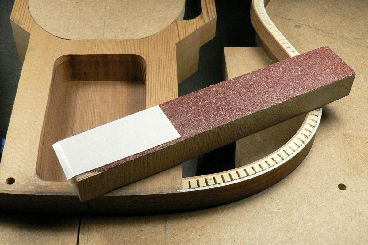
Then by keeping the taped end on the centre block I can sand the linings until the chalk is just rubbed off.
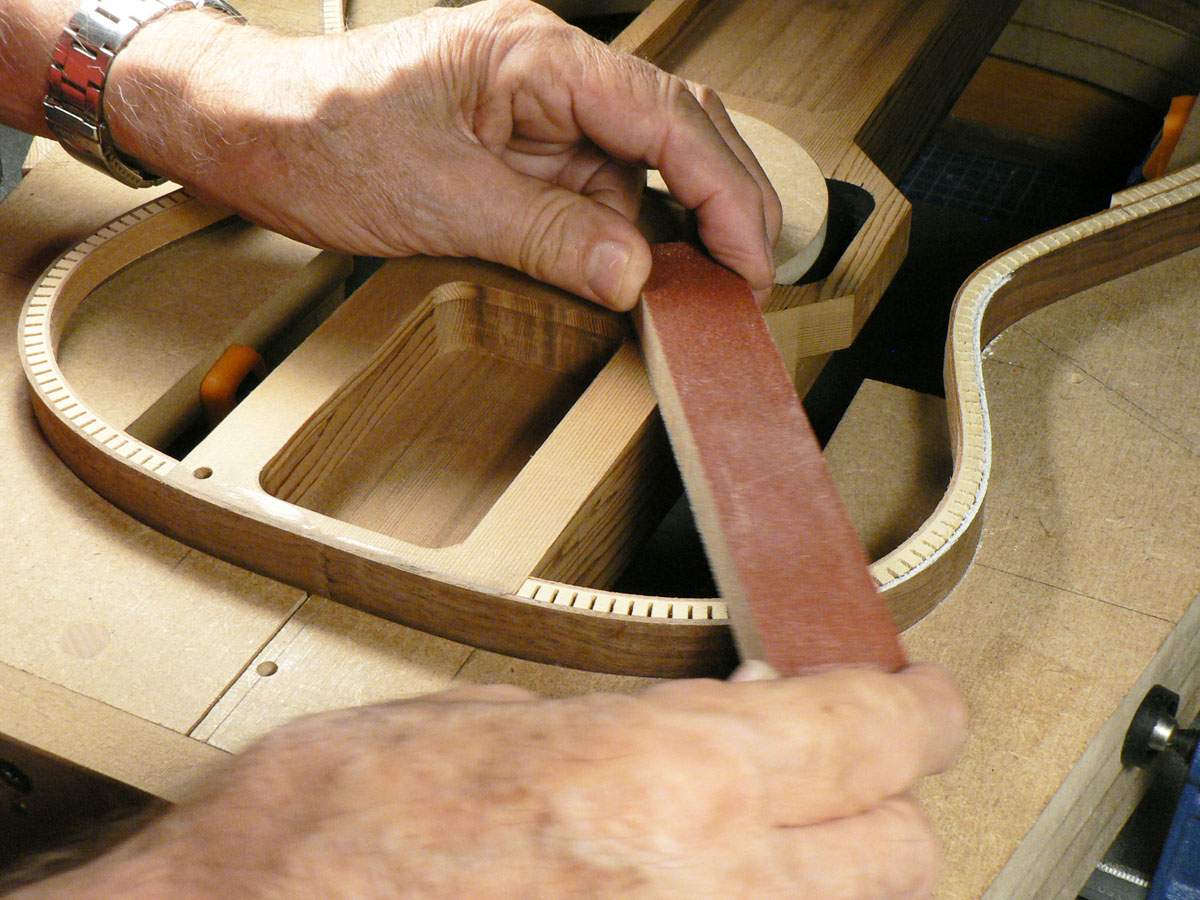
You can see where it’s started to be rubbed off in this photo.
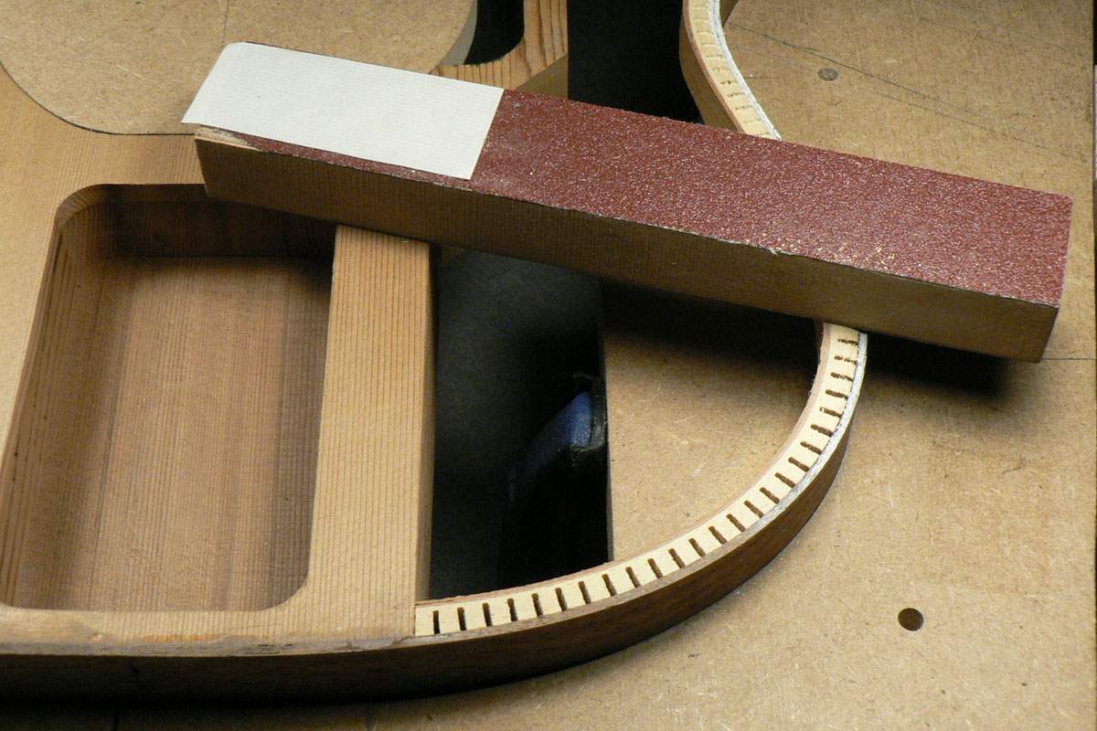
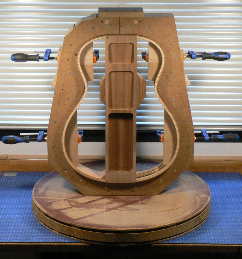
The back linings were glued on as near flush with the sides as possible and then the whole assembly including the centre block was chalked and sanded in the radius dish until the chalk had all gone.
Then by keeping the taped end on the centre block I can sand the linings until the chalk is just rubbed off.
You can see where it’s started to be rubbed off in this photo.
The back linings were glued on as near flush with the sides as possible and then the whole assembly including the centre block was chalked and sanded in the radius dish until the chalk had all gone.
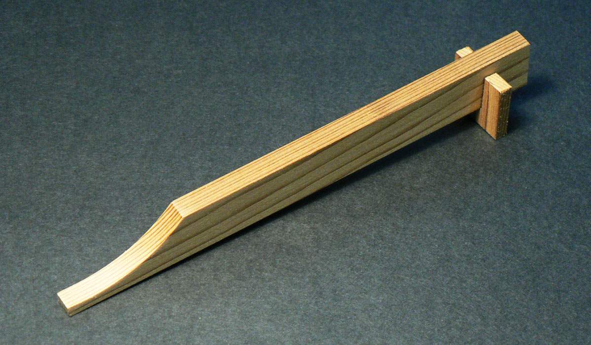
I decided to add some little back braces between the centre block and the sides as an additional help to keeping the domed shape. Here they are clamped together and chalked.
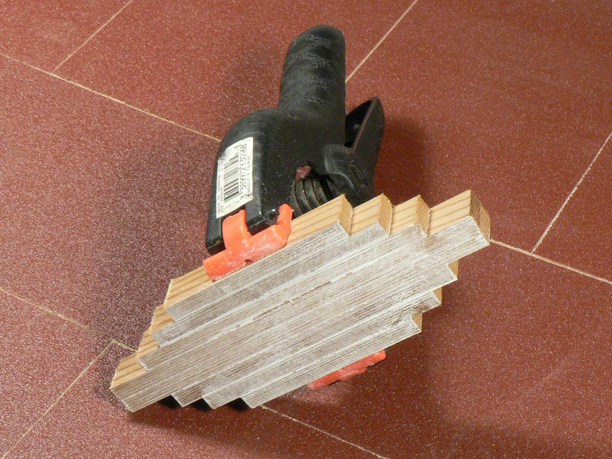
And here they are with the chalk sanded off.
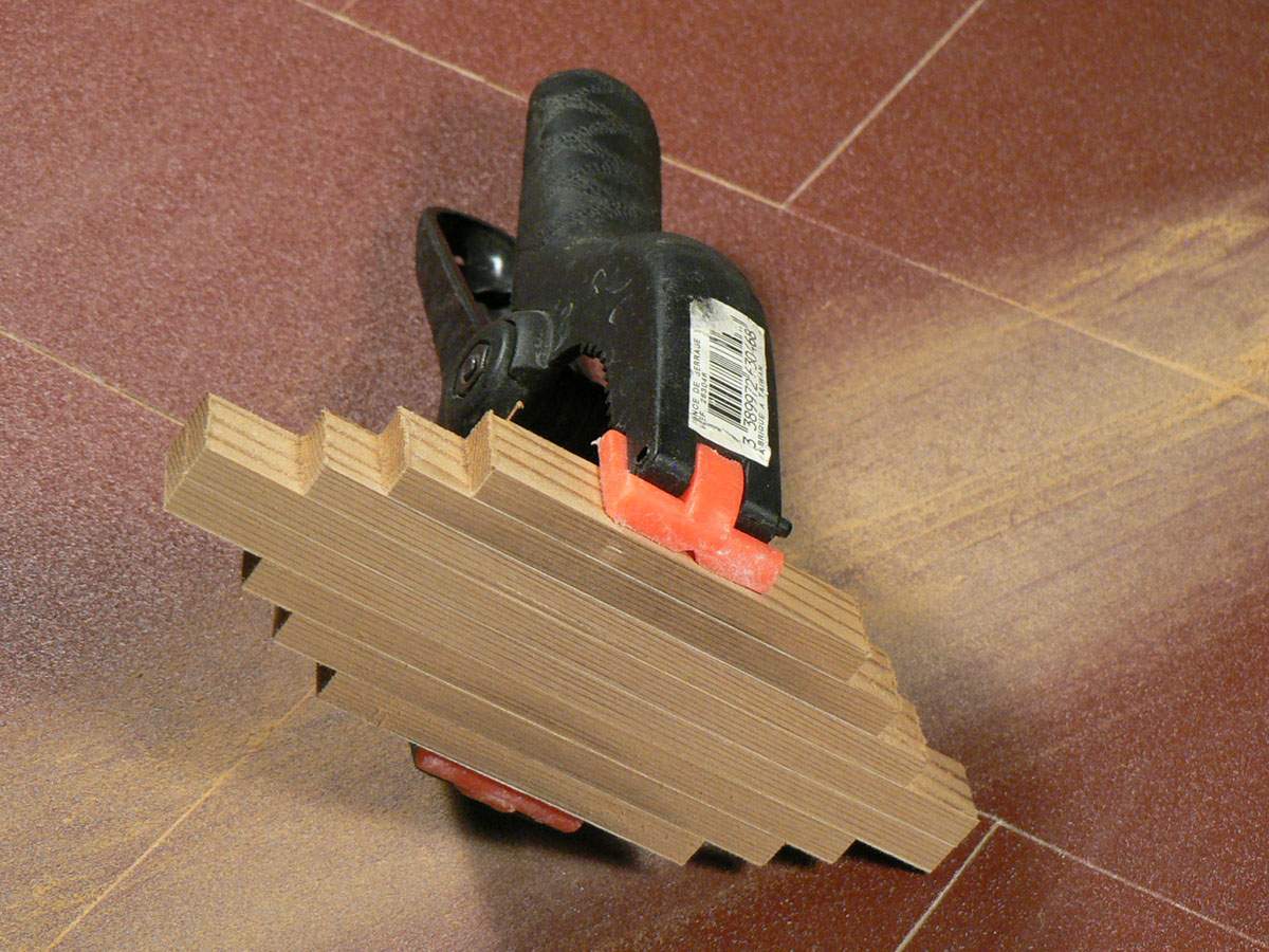
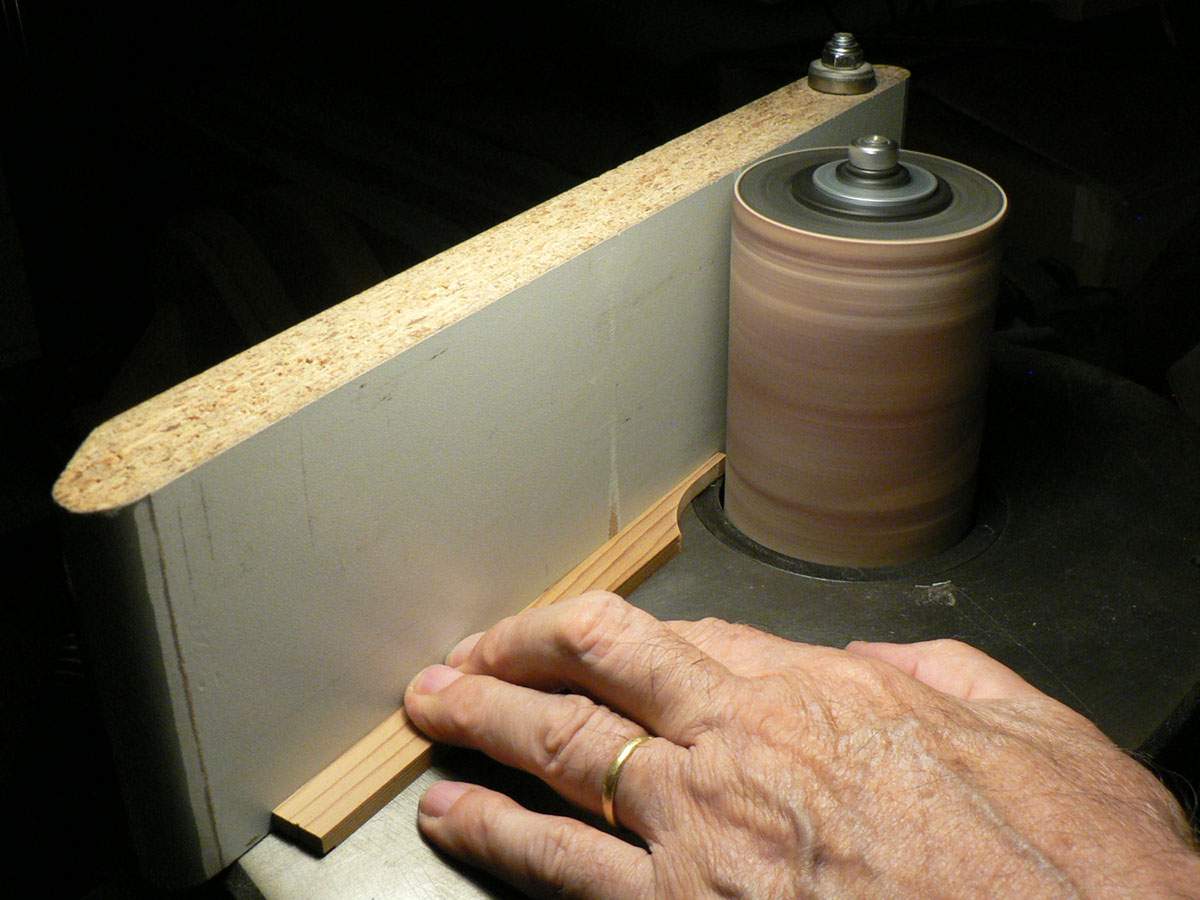
They then got one end sanded down to 3.2mm (1/8”) thick.
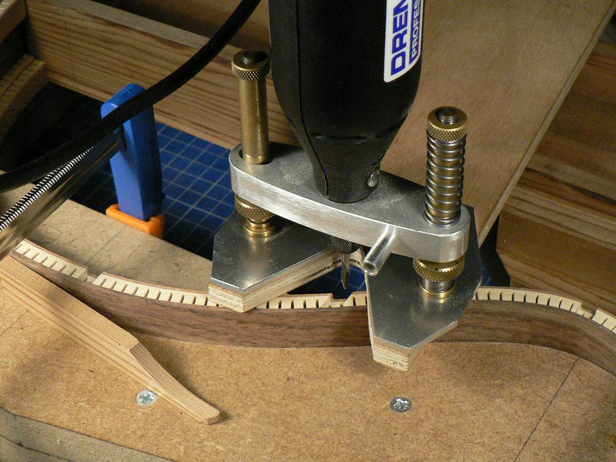
The linings were notched to receive the braces. The Dremel router base is mounted on a piece of plywood long enough to straddle the whole of the guitar body so that it’s perfectly stable when routing such a narrow surface. The notches are slightly shallower than the thickness of the braces.
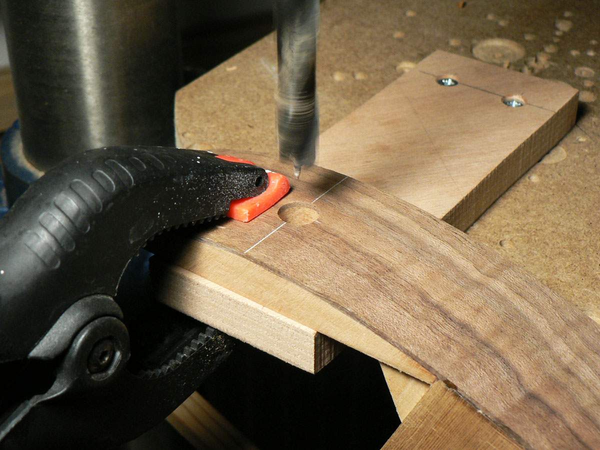
Before gluing the back braces in I drilled a hole for the jack socket. I was thinking that the braces would get in the way if I installed them first but, in fact, they wouldn’t have.
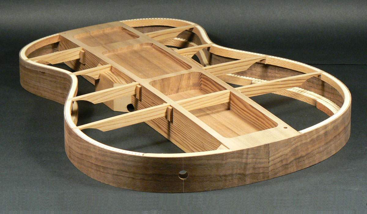
The braces were then trimmed to length so as to be a push fit between the centre block and the sides and glued in slightly proud of the centre block. Small ‘U’ shaped pieces of cedar were then glued around the braces to solidify them with the centre block. After that, the whole shebang was given a last rub in the radius dish to sand the braces flush with everything else.
And here they are with the chalk sanded off.
They then got one end sanded down to 3.2mm (1/8”) thick.
The linings were notched to receive the braces. The Dremel router base is mounted on a piece of plywood long enough to straddle the whole of the guitar body so that it’s perfectly stable when routing such a narrow surface. The notches are slightly shallower than the thickness of the braces.
Before gluing the back braces in I drilled a hole for the jack socket. I was thinking that the braces would get in the way if I installed them first but, in fact, they wouldn’t have.
The braces were then trimmed to length so as to be a push fit between the centre block and the sides and glued in slightly proud of the centre block. Small ‘U’ shaped pieces of cedar were then glued around the braces to solidify them with the centre block. After that, the whole shebang was given a last rub in the radius dish to sand the braces flush with everything else.
Now the back and sides are glued together in the radius dish.
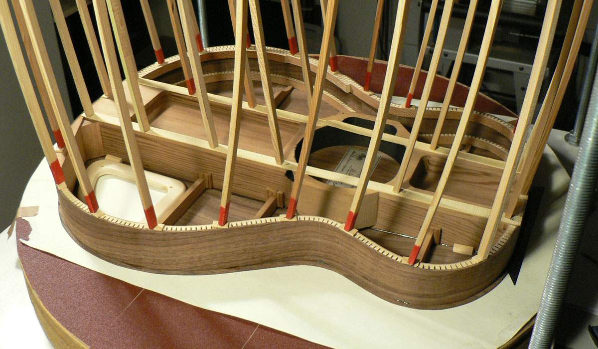
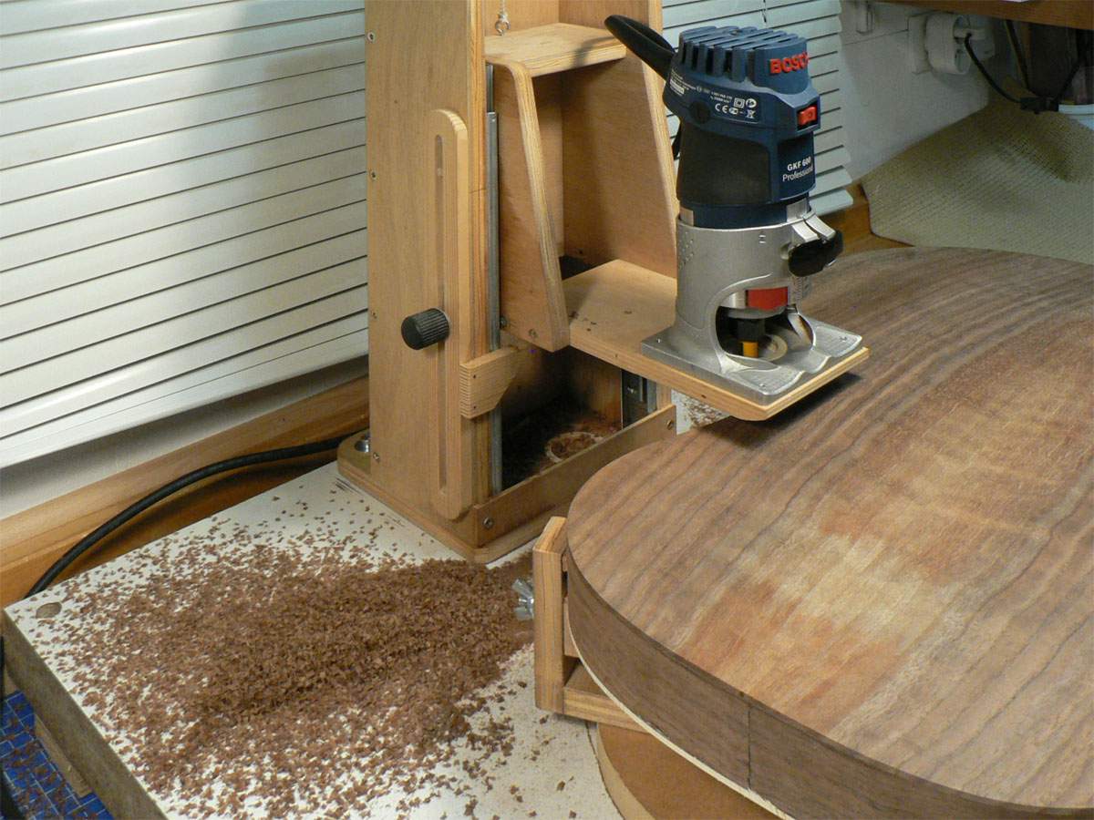
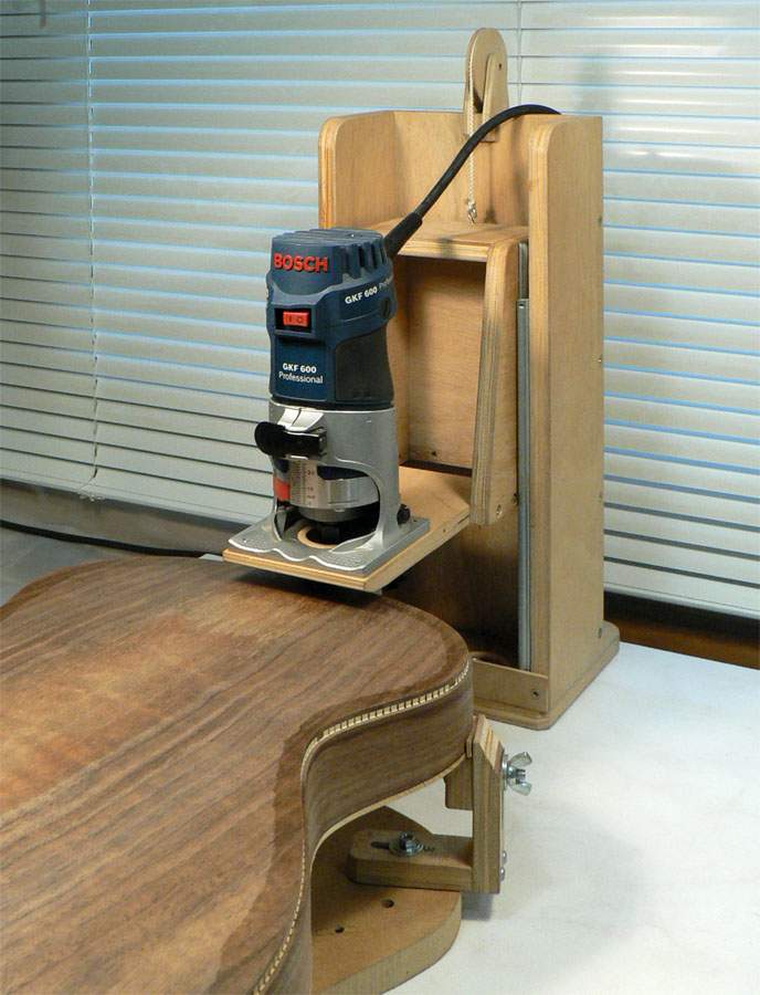
The back and sides were left in the dish and the front was glued on top (and I forgot to take a photo of that.). I trimmed the surplus off the back and front using the home-made binding router contraption with a flush-trim bit.
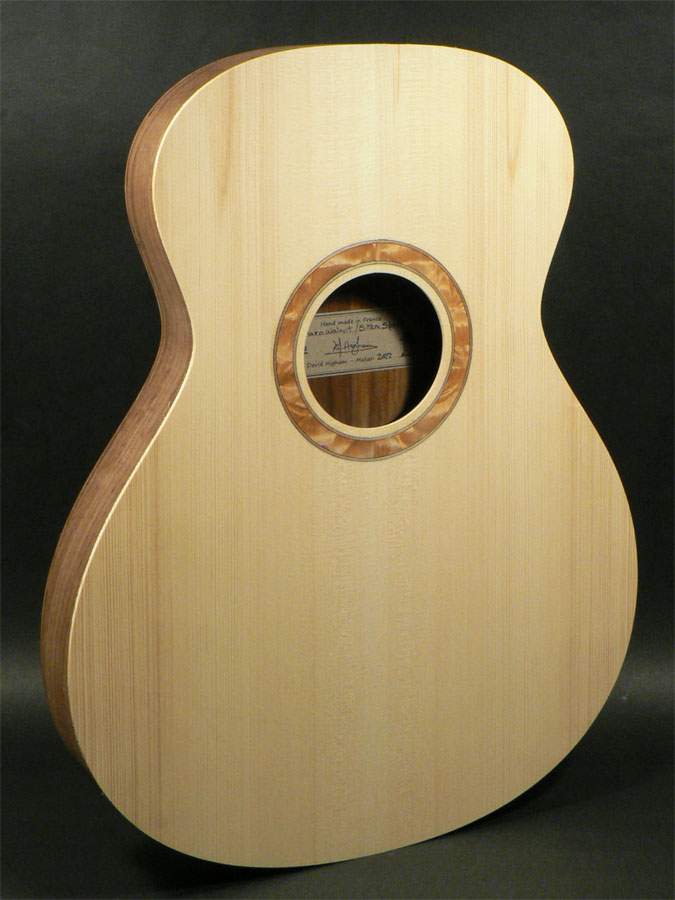
And we finally have a box.
The back and sides were left in the dish and the front was glued on top (and I forgot to take a photo of that.). I trimmed the surplus off the back and front using the home-made binding router contraption with a flush-trim bit.
And we finally have a box.

I love this project.
I'm slowly building muy first classical guitar and I seriously envy that jig for cutting the top and bottom flush with the sides, as I guess you'll use it to route the binding channel easily while I struggled with a shakey hand held router.
How are you planing the neck joint? Dovetail or some less traditional approach?
I'm slowly building muy first classical guitar and I seriously envy that jig for cutting the top and bottom flush with the sides, as I guess you'll use it to route the binding channel easily while I struggled with a shakey hand held router.
How are you planing the neck joint? Dovetail or some less traditional approach?
The binding router jig is home-made. Just about the only things you need to buy are a couple of drawer slides and some plywood.I love this project.
I'm slowly building muy first classical guitar and I seriously envy that jig for cutting the top and bottom flush with the sides, as I guess you'll use it to route the binding channel easily while I struggled with a shakey hand held router.
How are you planing the neck joint? Dovetail or some less traditional approach?
Neck joint definitely non-traditional. Closer to a Fender than a classical guitar.
This is something I should have done before gluing the back and front onto the sides. The wedge covers the join where the sides meet. This is usually just at the lower bout but as I won’t have a heel covering the joint I’ll have to have one there too.
Careful use of a craft knife and chisel to cut out a wedge shape.
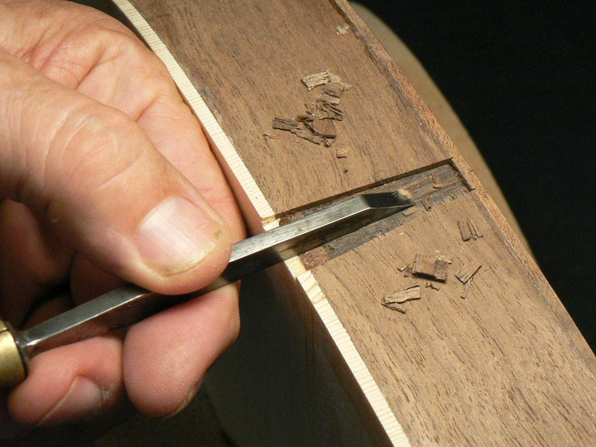
The wedges were cut from off-cuts from when the sides were trimmed to length and sanded until they just fit with 2 pieces of maple veneer.
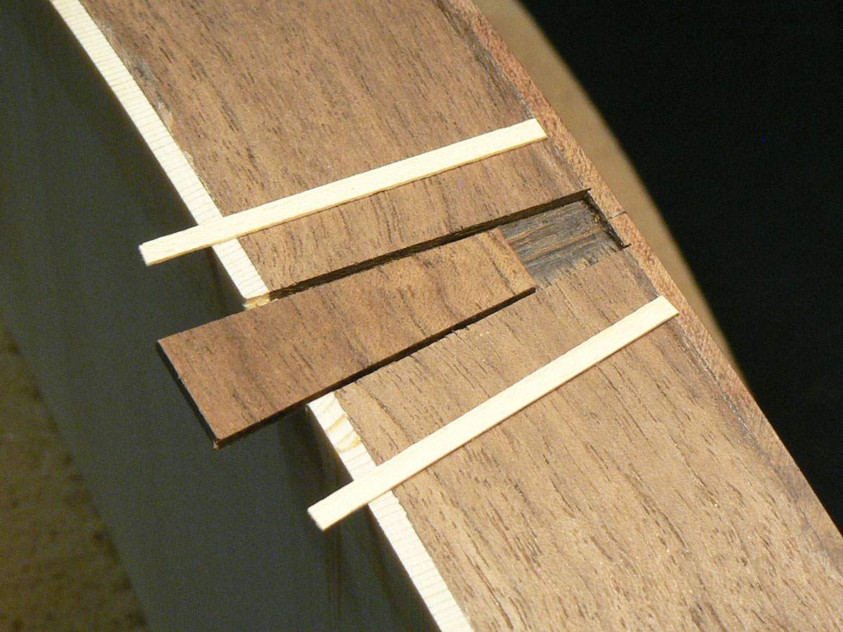
Wedge glued in. . .
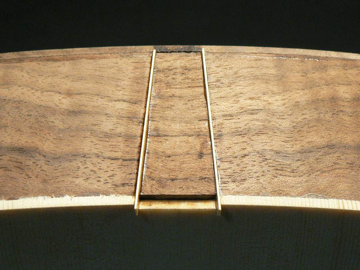
. . .and trimmed flush. (The photos are a mixture of the 2 wedges).
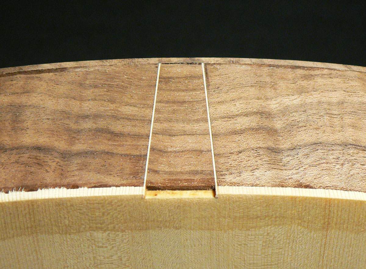
Careful use of a craft knife and chisel to cut out a wedge shape.
The wedges were cut from off-cuts from when the sides were trimmed to length and sanded until they just fit with 2 pieces of maple veneer.
Wedge glued in. . .
. . .and trimmed flush. (The photos are a mixture of the 2 wedges).
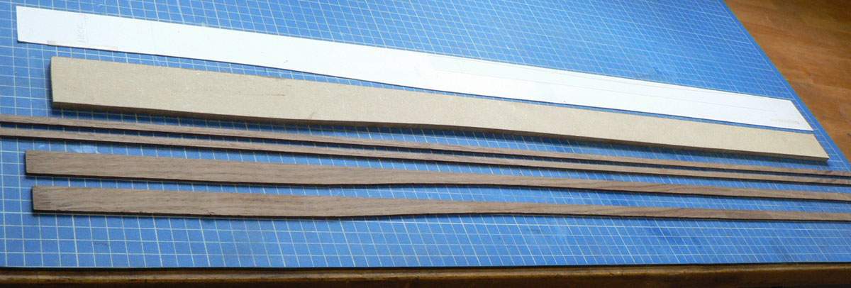
The next step is to bind the box. The wood for the sides was wide enough to make an acoustic guitar, so there’s a lot of it left and I’m going to use it for the bindings. As I cut the sides to the profiled shape, the off-cuts have that shape so I’ll make the back bindings that shape, but the profiled edge was bandsawn and needs to be clean and square so I made a MDF template to the profiled shape. The 2 straight pieces are for the front .
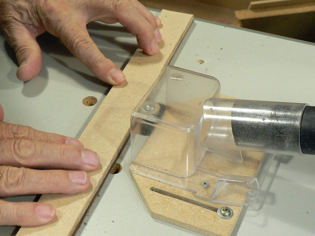
The template was attached to the bindings with double sided tape and the edge cleaned up on the router table.
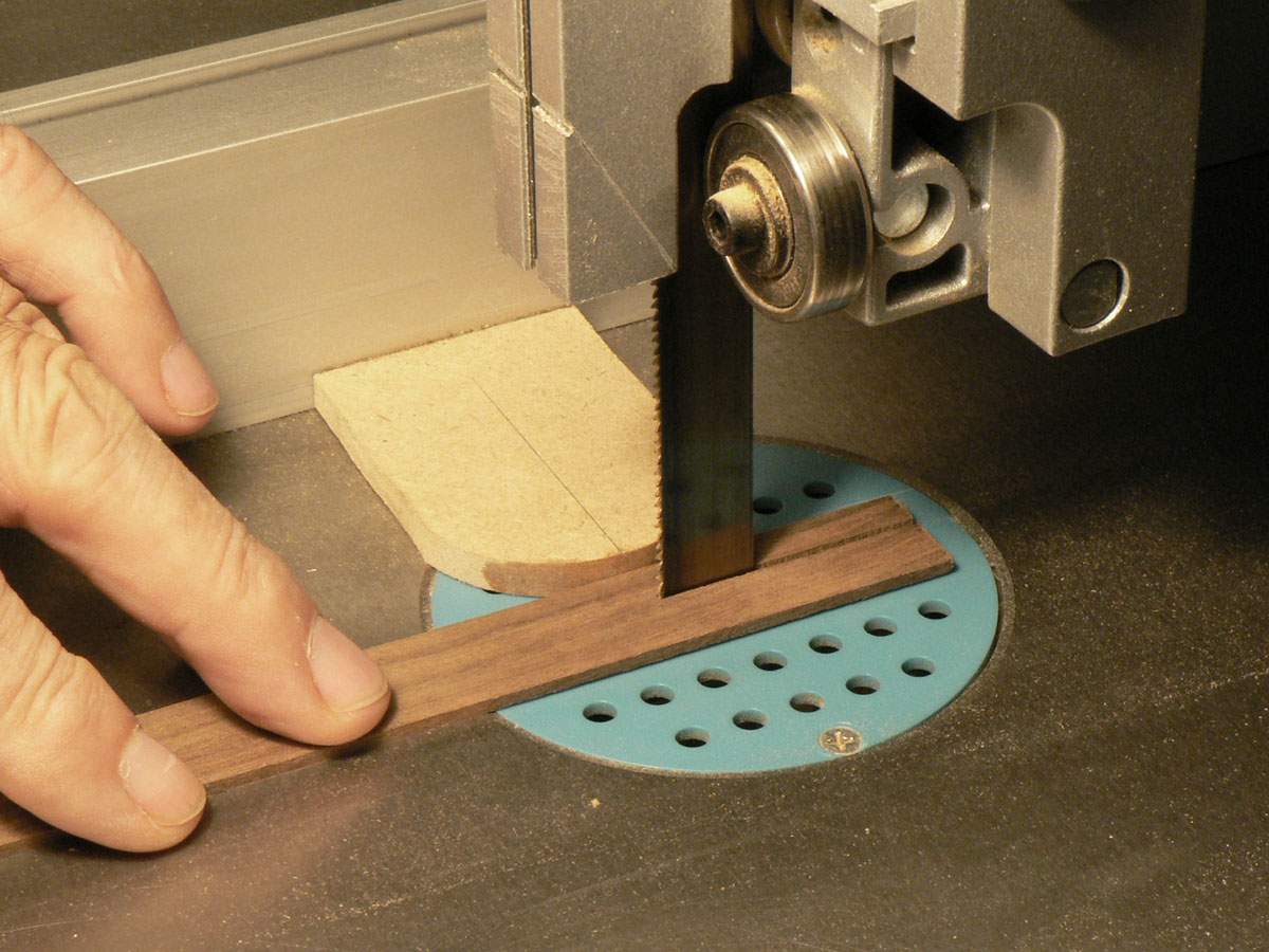
The back bindings were cut to the width required on the bandsaw allowing about a millimetre for trimming. This sawn edge doesn’t need to be cleaned up, as it will be trimmed flush with the back after installation.
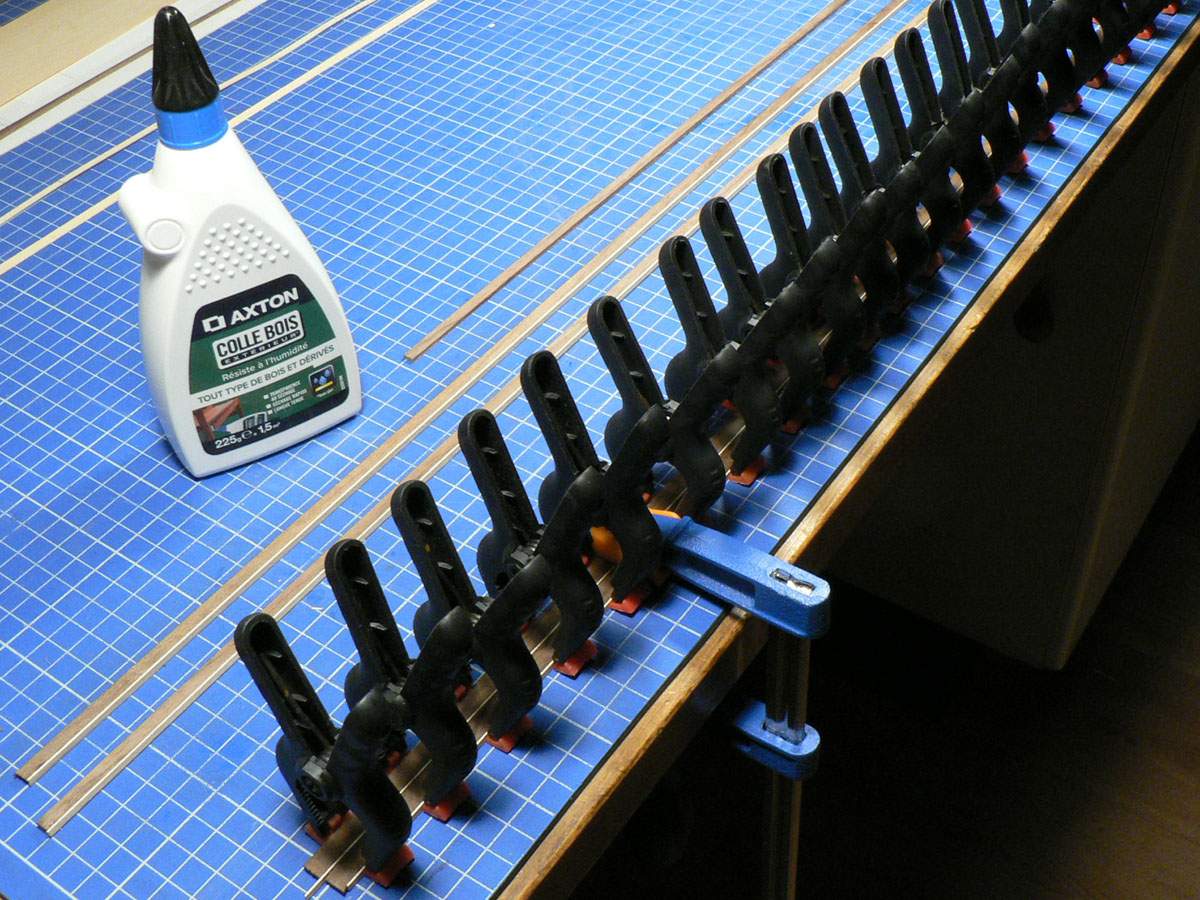
There’ll be a white veneer purfling line between the bindings and the sides and this is glued on using waterproof wood glue so it will survive the heat and steam of the bending process.
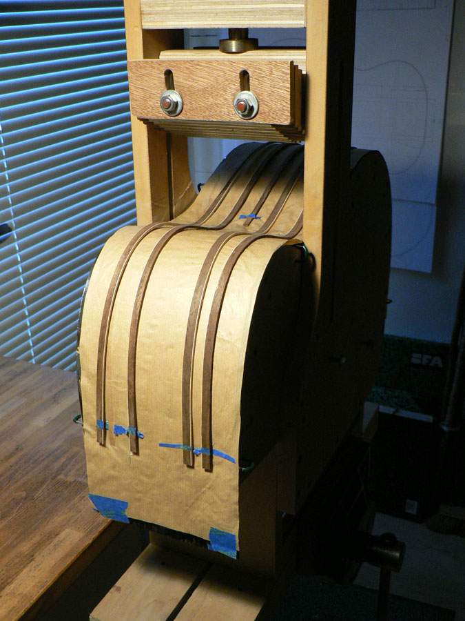
The bindings are bent in the same way as the sides. When they come out of the machine there’s a bit of spring-back, but they are quite easily pushed into place.
The template was attached to the bindings with double sided tape and the edge cleaned up on the router table.
The back bindings were cut to the width required on the bandsaw allowing about a millimetre for trimming. This sawn edge doesn’t need to be cleaned up, as it will be trimmed flush with the back after installation.
There’ll be a white veneer purfling line between the bindings and the sides and this is glued on using waterproof wood glue so it will survive the heat and steam of the bending process.
The bindings are bent in the same way as the sides. When they come out of the machine there’s a bit of spring-back, but they are quite easily pushed into place.
Rebates now have to be cut around the front and back edges of the box for the bindings.
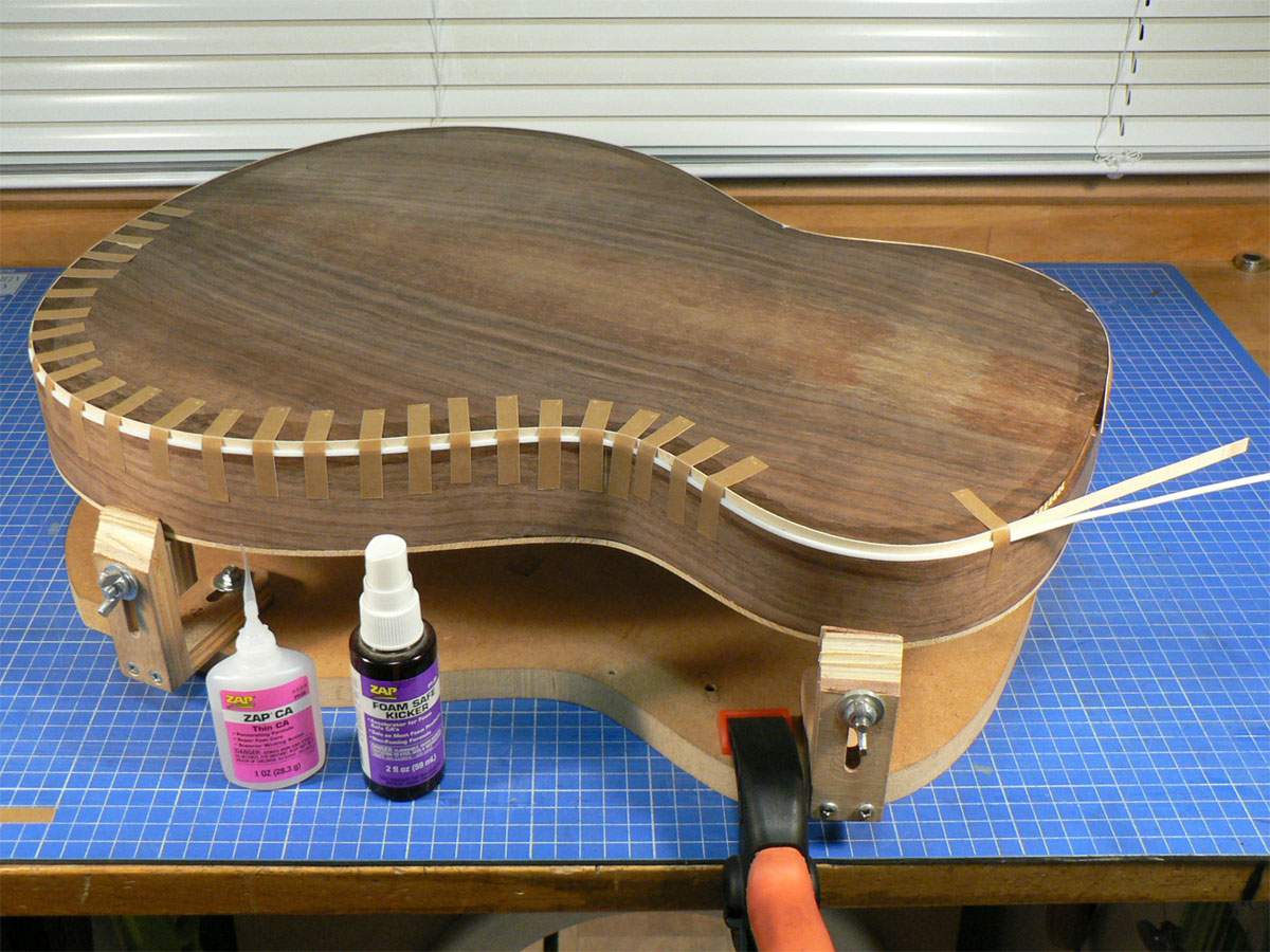
The back will have a single white veneer purfling line and I glue this in first. The purfling is taped in place and a drop of thin CA is applied in the gaps between the tapes. The thinner of the two white strips in the photo is a Teflon strip which helps push the veneer strip into the corner of the rebate. I push the veneer into the rebate as I apply the glue to make sure it’s in good contact and sometimes glue my fingers to it as well.
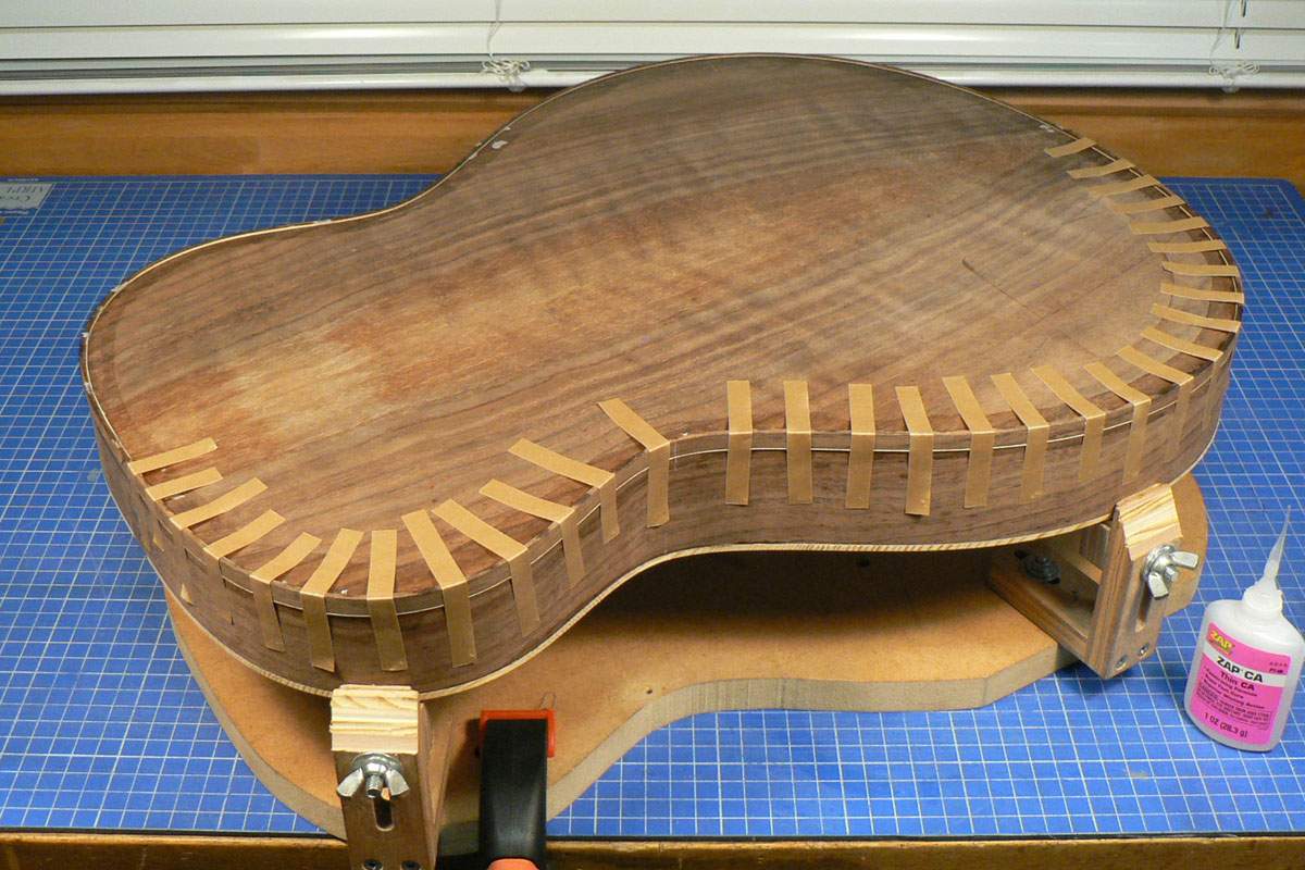
The bindings are fitted in the same way as the purfling strips. The rebates were cut slightly narrower than the thickness of the bindings. It’s easier to scrape the bindings down flush with the sides than to scrape the sides down to the bindings.
The back will have a single white veneer purfling line and I glue this in first. The purfling is taped in place and a drop of thin CA is applied in the gaps between the tapes. The thinner of the two white strips in the photo is a Teflon strip which helps push the veneer strip into the corner of the rebate. I push the veneer into the rebate as I apply the glue to make sure it’s in good contact and sometimes glue my fingers to it as well.
The bindings are fitted in the same way as the purfling strips. The rebates were cut slightly narrower than the thickness of the bindings. It’s easier to scrape the bindings down flush with the sides than to scrape the sides down to the bindings.
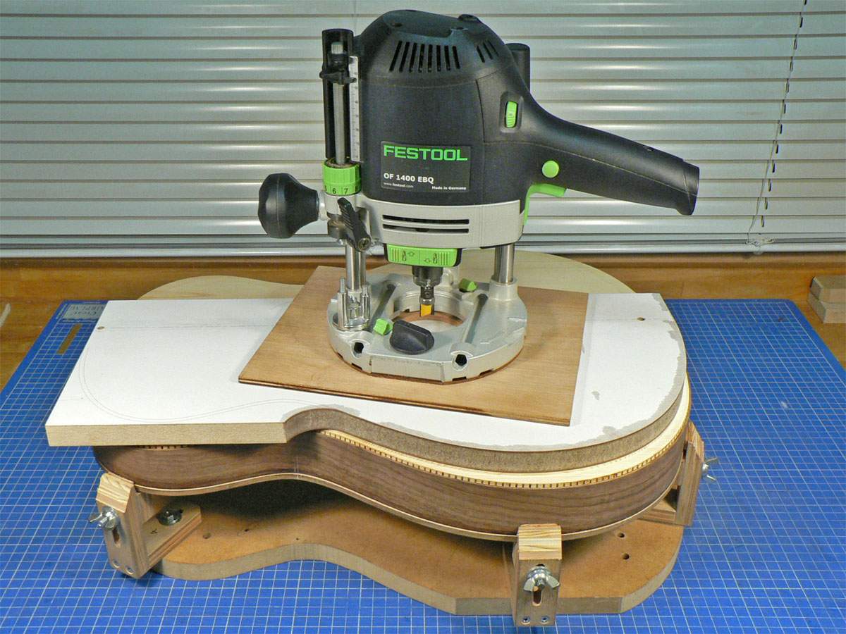
Binding the front is more complicated. First of all there are 2 rebates; one for the binding and a wider, shallower one for three purfling strips. The purfling rebate is then modified for the armrest bevel using the template shown. The template was fixed using two dowels as I wasn’t too sure about fixing it to the top with double sided tape. The one on the left is in the area of the neck pocket and the one on the right will be hidden under the bridge.
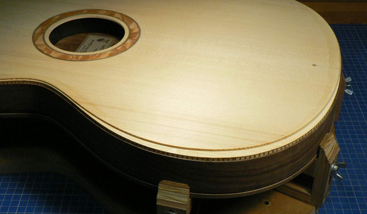
This is what the binding rebates look like.
I glued in the purfling strips all the way round, in the same way as I did on the back and then added this extra strip of binding around the area of the bevel.
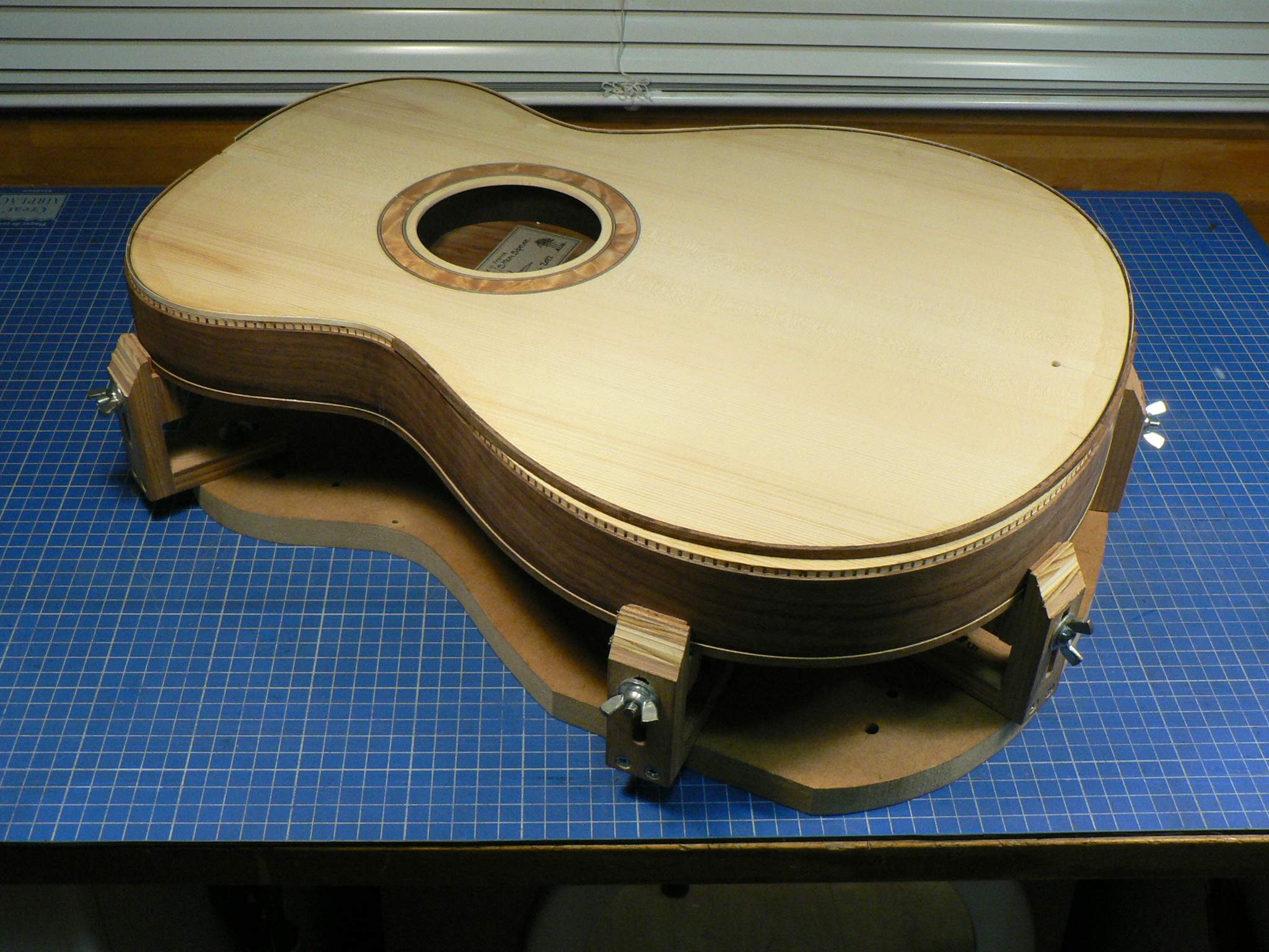
I then put the body back on the binding router set up and ran it round the binding rebate again. Not taking any more off the rebate but tapering the ends of this piece of binding down to nothing.
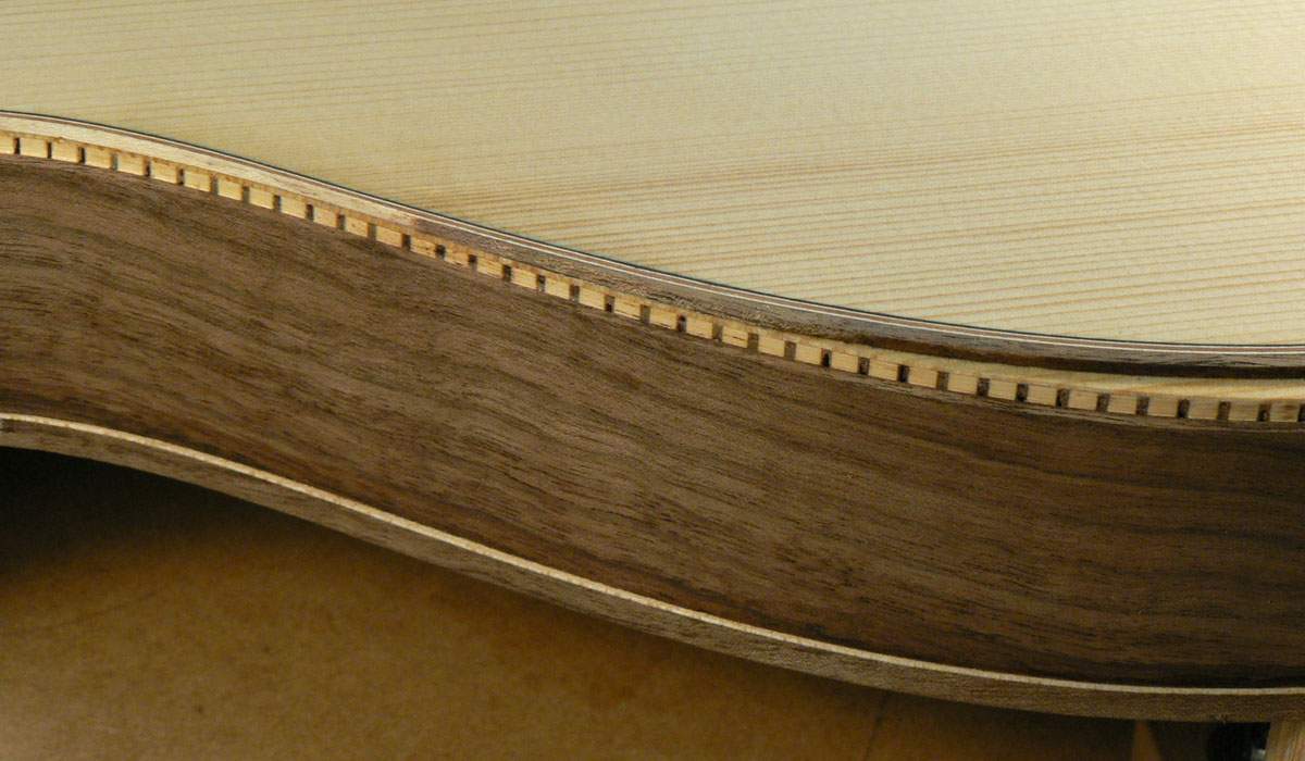
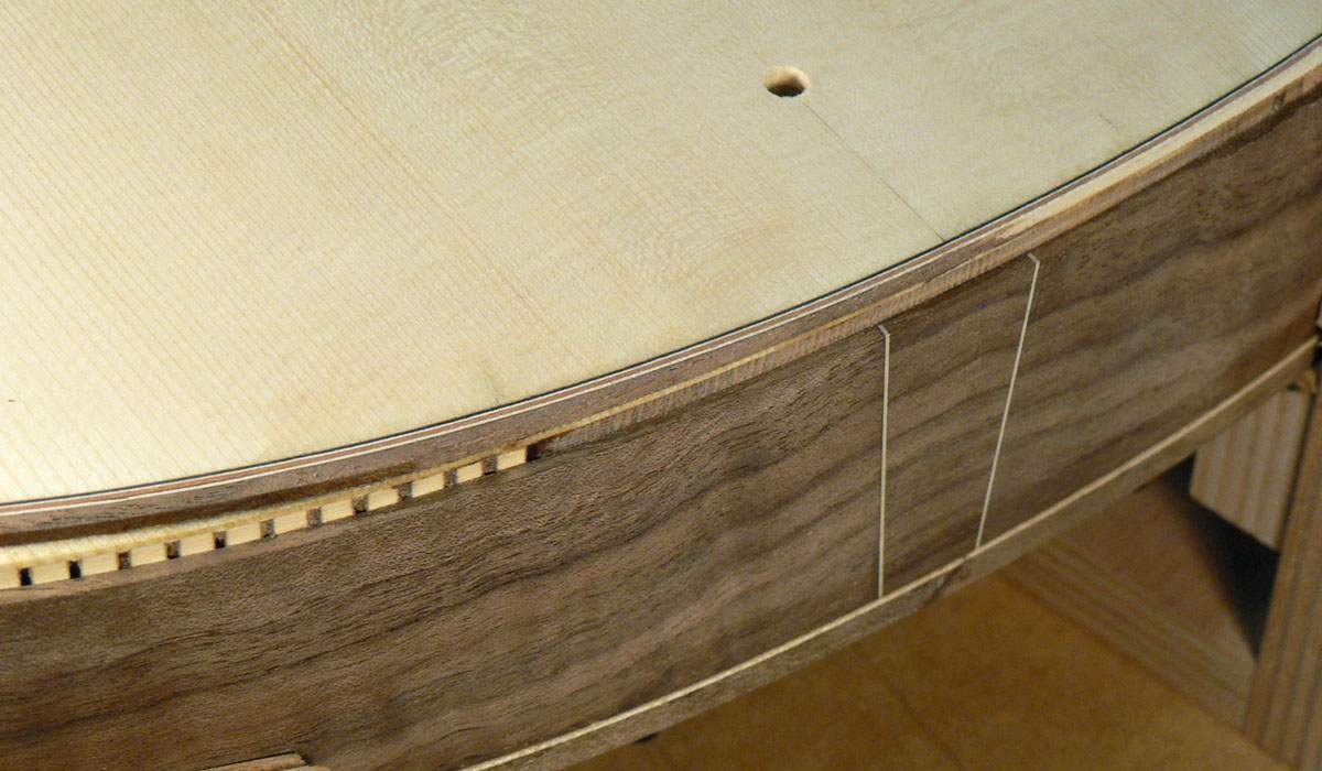
The outer binding is then fitted. The binding rebate has been modified on the side just as it was on the top by cutting it deeper to match the top. This was done very slowly and painstakingly using craft knife and chisels and I’m afraid I forgot to take photos. The binding has also been reduced in height in this area to make it flexible enough to be pushed down into the rebate
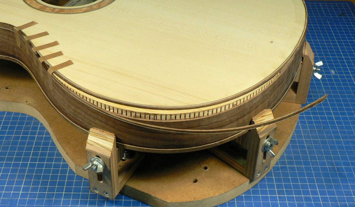
The binding all glued in.
This is what the binding rebates look like.
I glued in the purfling strips all the way round, in the same way as I did on the back and then added this extra strip of binding around the area of the bevel.
I then put the body back on the binding router set up and ran it round the binding rebate again. Not taking any more off the rebate but tapering the ends of this piece of binding down to nothing.
The outer binding is then fitted. The binding rebate has been modified on the side just as it was on the top by cutting it deeper to match the top. This was done very slowly and painstakingly using craft knife and chisels and I’m afraid I forgot to take photos. The binding has also been reduced in height in this area to make it flexible enough to be pushed down into the rebate
The binding all glued in.


Binding the front is more complicated. First of all there are 2 rebates; one for the binding and a wider, shallower one for three purfling strips. The purfling rebate is then modified for the armrest bevel using the template shown. The template was fixed using two dowels as I wasn’t too sure about fixing it to the top with double sided tape. The one on the left is in the area of the neck pocket and the one on the right will be hidden under the bridge.View attachment 4863927
This is what the binding rebates look like.View attachment 4863928
I glued in the purfling strips all the way round, in the same way as I did on the back and then added this extra strip of binding around the area of the bevel.View attachment 4863929
I then put the body back on the binding router set up and ran it round the binding rebate again. Not taking any more off the rebate but tapering the ends of this piece of binding down to nothing.View attachment 4863930
View attachment 4863931
The outer binding is then fitted. The binding rebate has been modified on the side just as it was on the top by cutting it deeper to match the top. This was done very slowly and painstakingly using craft knife and chisels and I’m afraid I forgot to take photos. The binding has also been reduced in height in this area to make it flexible enough to be pushed down into the rebate
View attachment 4863933
The binding all glued in.View attachment 4863934
Great stuff. There’s a couple of the acoustic builders I watch on YouTube that have recently made guitars with armrest cutouts. It’s an interesting process.
Yes, there are various ways of doing it. Many luthiers offer an armrest of some sort and even Taylor Guitars does them. Some even do a 'rib rest' on the back of the waist.Great stuff. There’s a couple of the acoustic builders I watch on YouTube that have recently made guitars with armrest cutouts. It’s an interesting process.
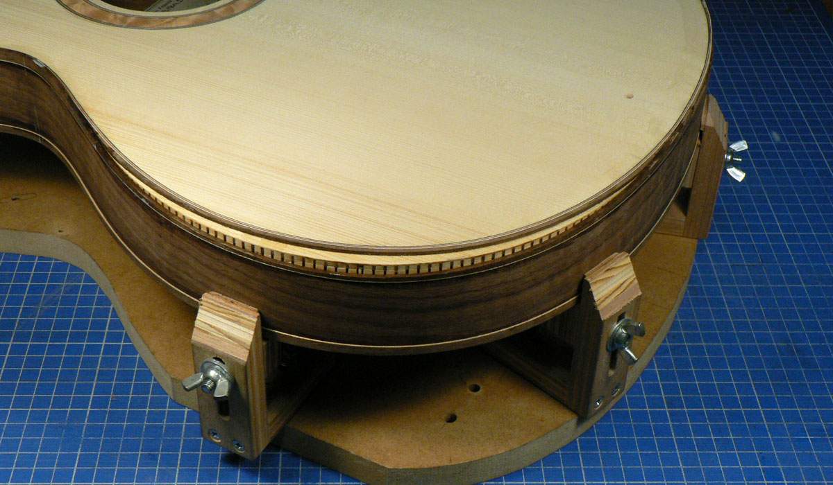
Some of the exposed linings is shaved off at 45° to the top until the spokeshave starts to touch the bindings.
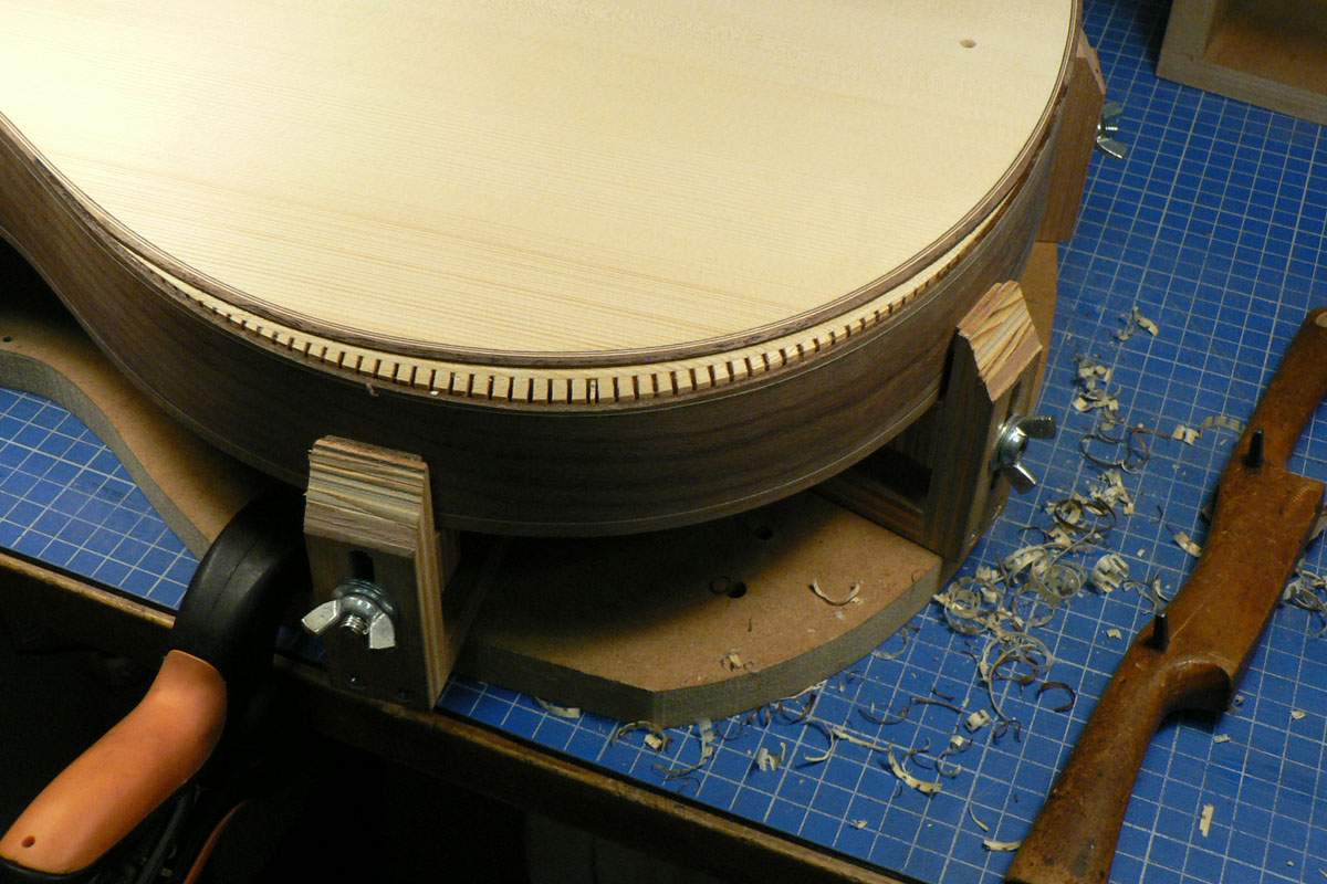 The bevel is then finished by sanding it using this thing. It has 80 grit abrasive stuck to it and by carefully sliding it round the body I can get a constant 45° bevel with no wobbles. I sand until there’s about 1/32” left of the binding on the horizontal and vertical faces.
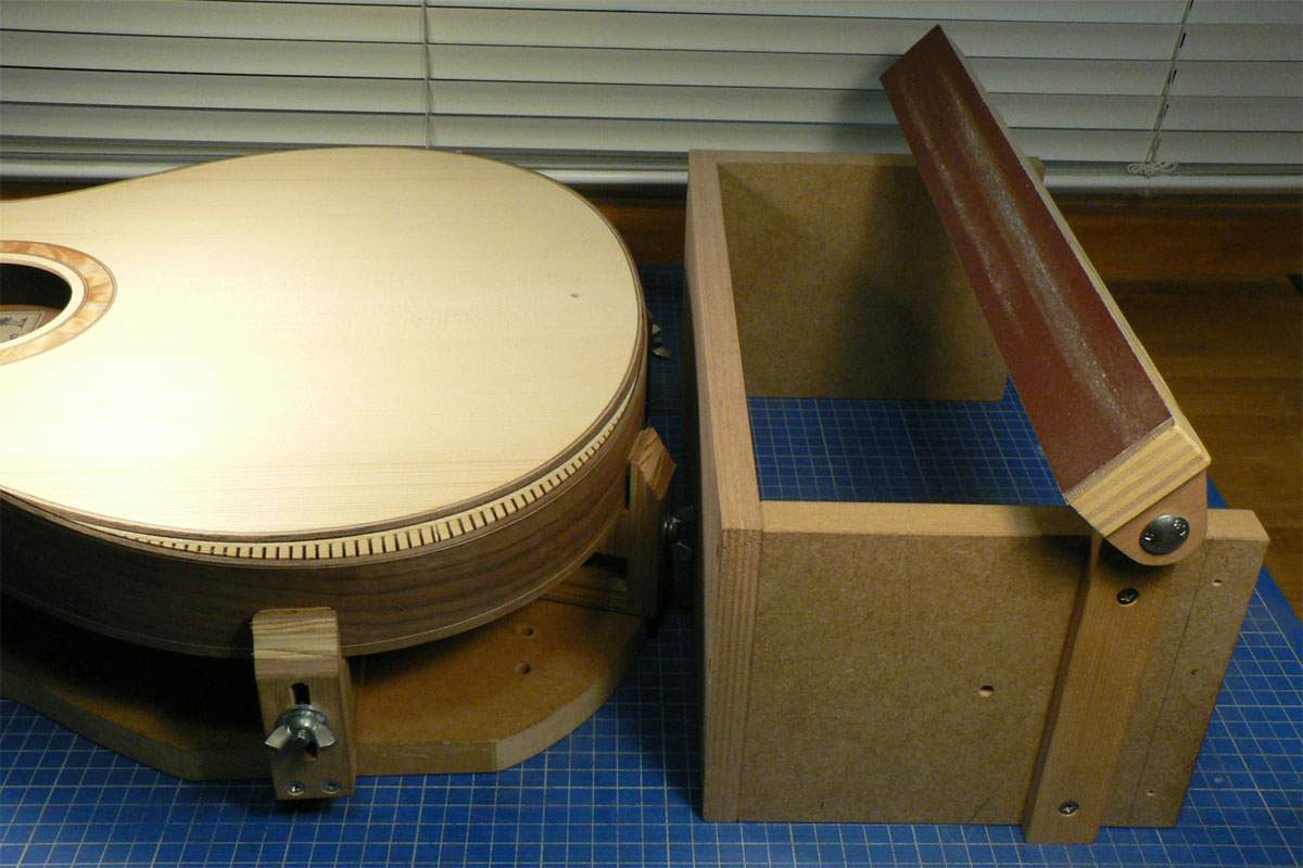
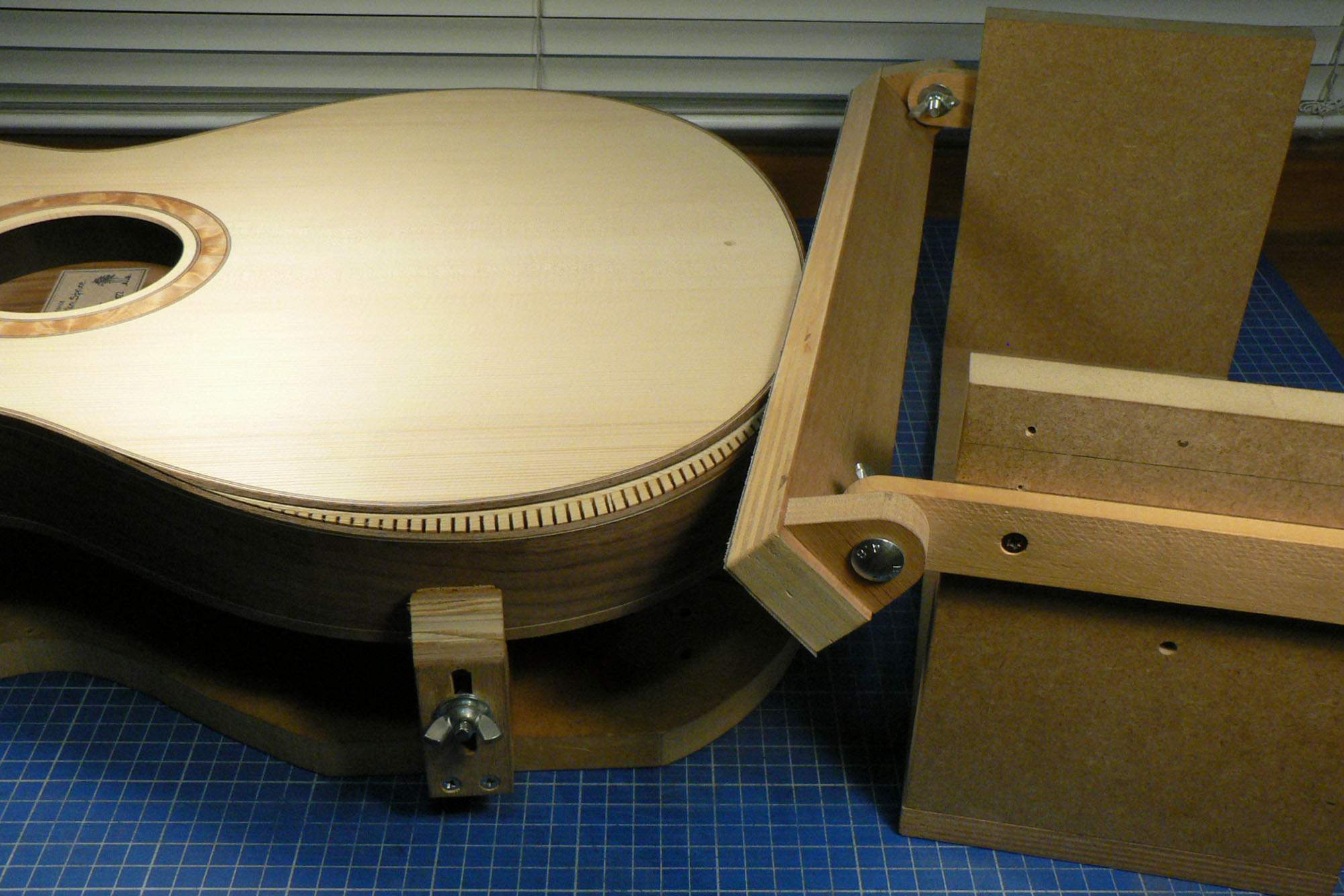
A piece of paper is stuck onto the bevel using repositionable spray adhesive and the outline of the bevel traced.
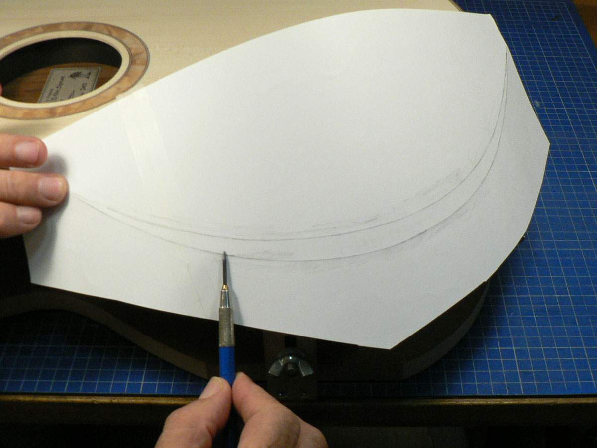
The shape is cut out adding about 3mm extra all round. I then take an off-cut of the back, big enough to cover the paper pattern, and sand it down to about 1.2mm (0.048”) thick. This makes it flexible enough to bend round the shape of the bevel. The pattern is stuck to it and the shape cut out.
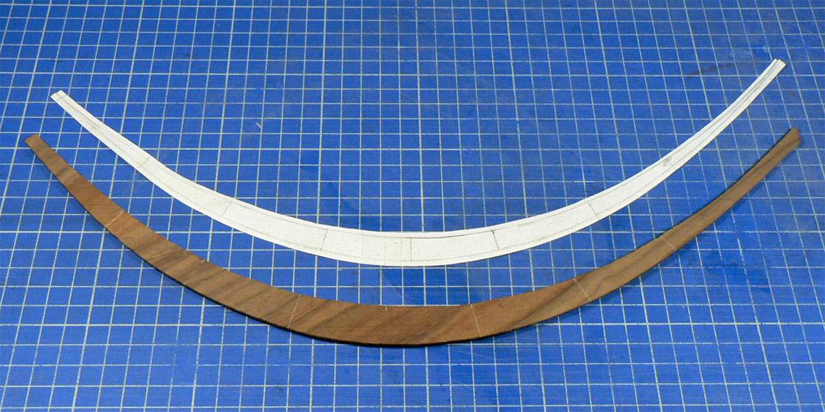
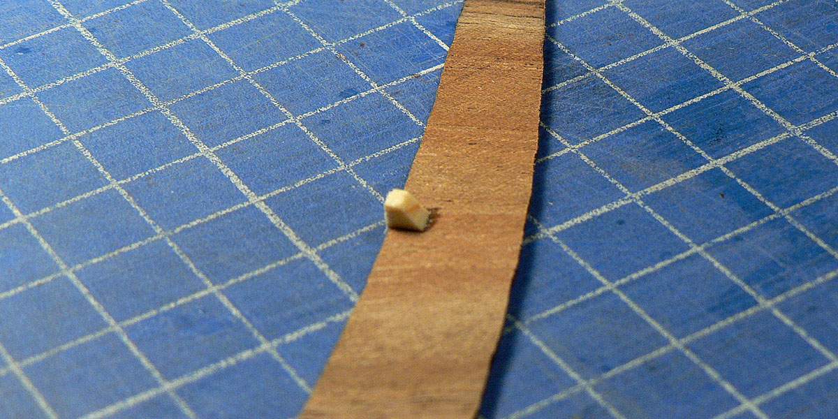
I then cut the surplus off the inside curve of the pattern, turn the wood and the pattern over (so I’m looking at the surface which will be glued to the bevel) and stick the pattern back onto the wood. I then glue some tiny triangular blocks of wood to the veneer just touching the paper pattern. These will help to position the veneer when gluing it onto the bevel.
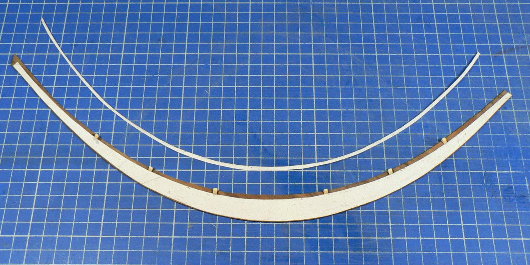
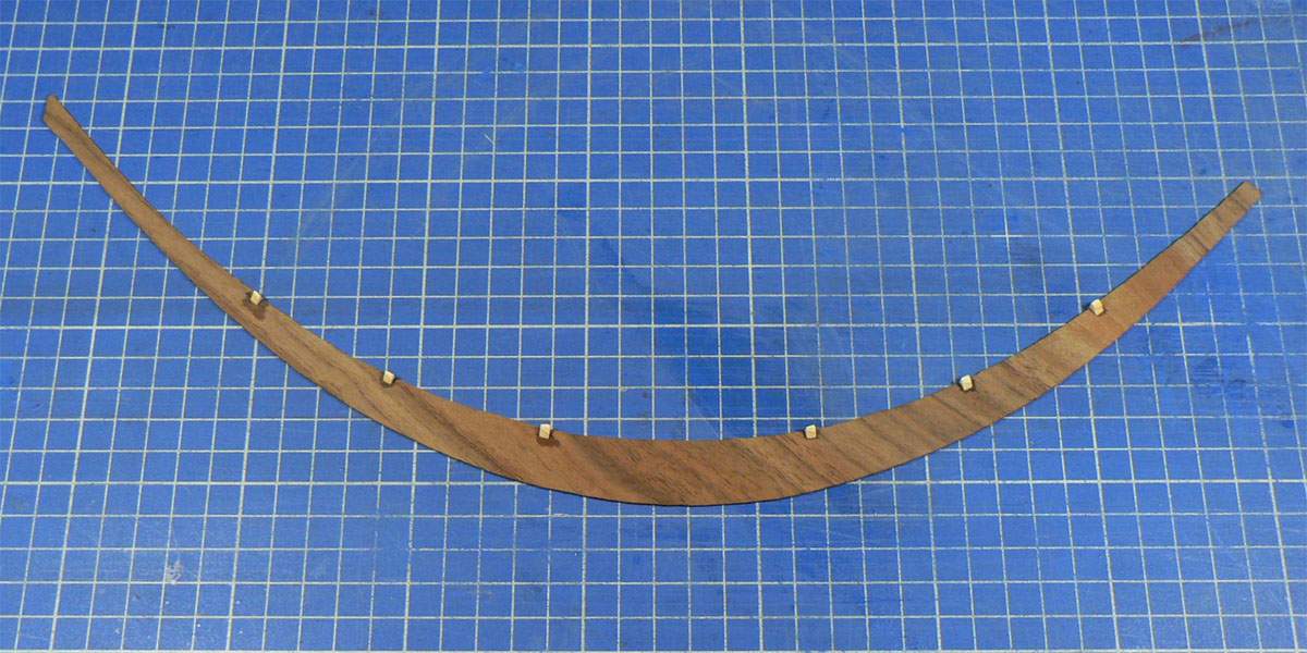
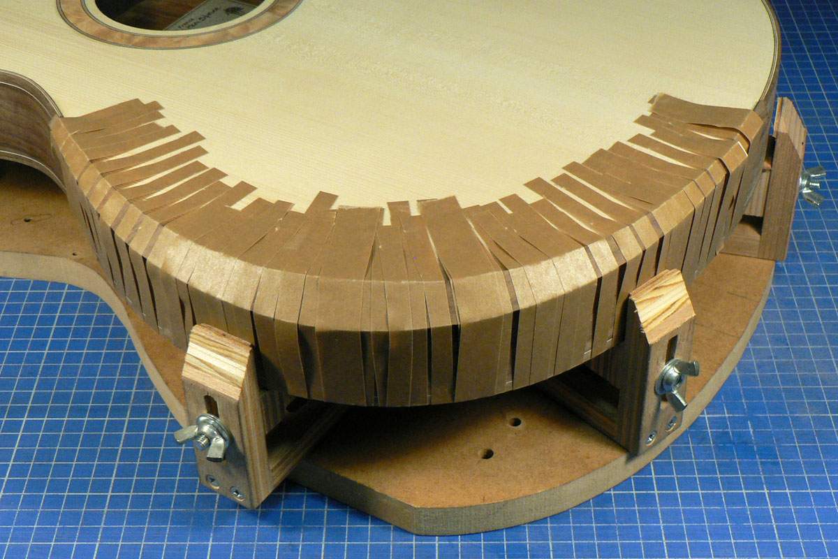
I glued the veneer on using Epoxy and a lot of tape.
A piece of paper is stuck onto the bevel using repositionable spray adhesive and the outline of the bevel traced.
The shape is cut out adding about 3mm extra all round. I then take an off-cut of the back, big enough to cover the paper pattern, and sand it down to about 1.2mm (0.048”) thick. This makes it flexible enough to bend round the shape of the bevel. The pattern is stuck to it and the shape cut out.
I then cut the surplus off the inside curve of the pattern, turn the wood and the pattern over (so I’m looking at the surface which will be glued to the bevel) and stick the pattern back onto the wood. I then glue some tiny triangular blocks of wood to the veneer just touching the paper pattern. These will help to position the veneer when gluing it onto the bevel.
I glued the veneer on using Epoxy and a lot of tape.

Thank you, but it's far from masterful. I know how to hide my mistakes (at least from the camera).Amazing!
This is one of my favorite build threads. It is amazing to watch your masterful work come together.

So this is what it looked like when I got all the tape off.
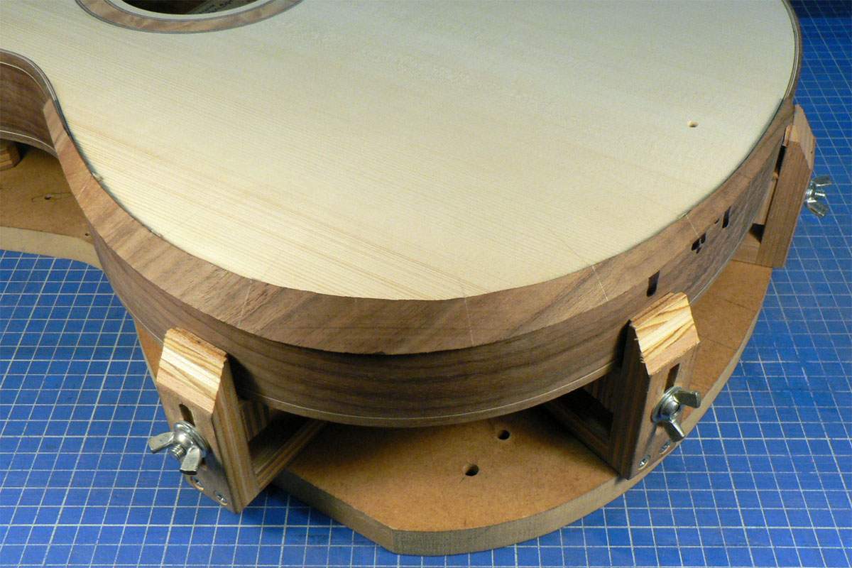
The little triangular blocks helped to position the veneer perfectly. It overhung the top and sides all the way round.
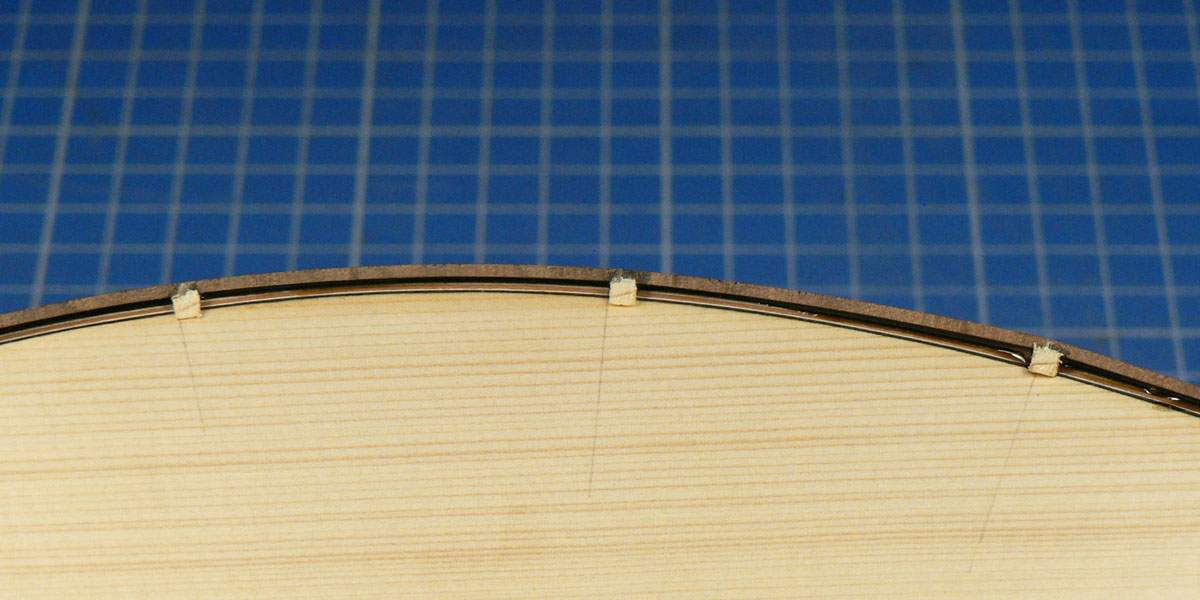
I trimmed the surplus off the sides on the binding router jig again using a flush-trim bit.
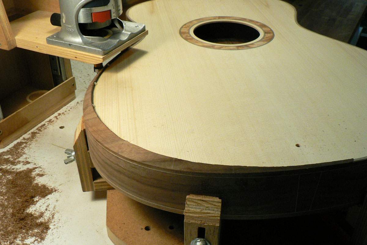
Trimming the top is more tricky as it’s shaved down to nothing at each end. I used a block plane with a sharp blade taking very light shavings and finished off with a scraper.
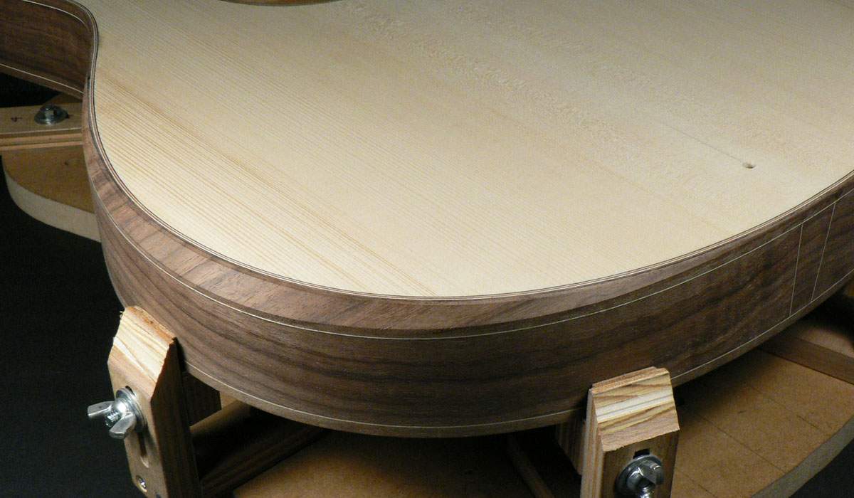
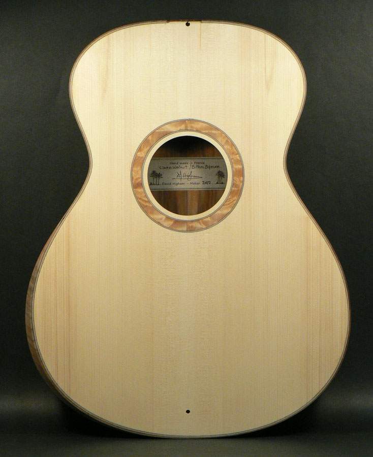
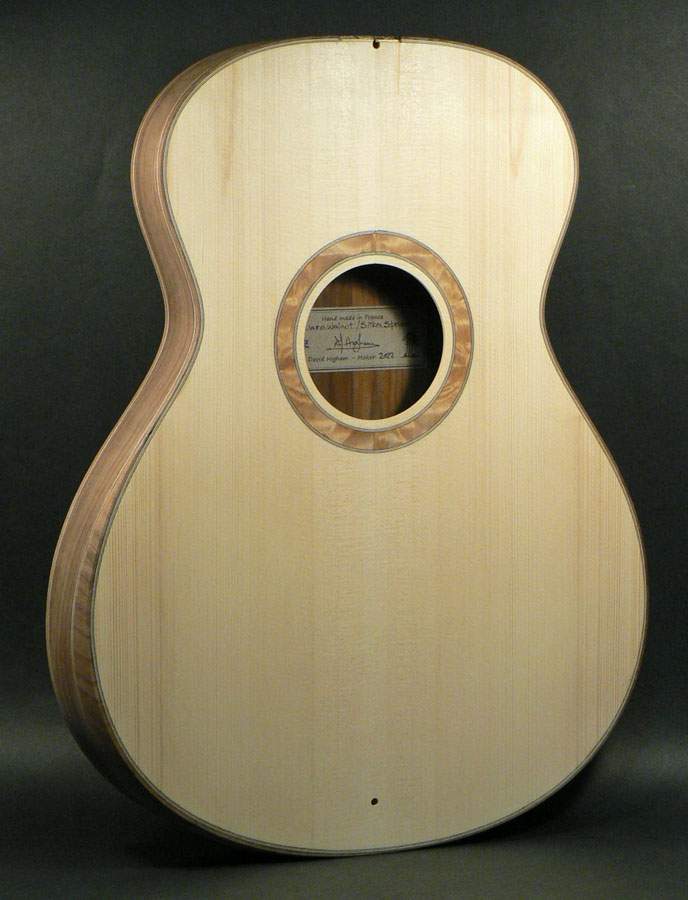
The little triangular blocks helped to position the veneer perfectly. It overhung the top and sides all the way round.
I trimmed the surplus off the sides on the binding router jig again using a flush-trim bit.
Trimming the top is more tricky as it’s shaved down to nothing at each end. I used a block plane with a sharp blade taking very light shavings and finished off with a scraper.

That reminds me… When I was first apprenticed as a cabinet maker long ago, I had the good fortune to be taught by a 60-something Italian man, the very definition of old world master craftsman. He didn’t speak much English (nor I Italian) but he communicated through demonstration and affirmative and negative reactions to my skills. Nevertheless, there was one piece of English he knew well, and used when appropriate… “Ach”, he’d say, “customer no see!”Thank you, but it's far from masterful. I know how to hide my mistakes (at least from the camera).


