• TalkBass has been independent since 1998. Add your voice.
    Create a free account to reply to discussions, view embedded media, and browse with fewer display ads.
    Join freeLog in
    Want zero display ads or expanded classifieds tools? Compare plans.

Building Your Own Custom Truss Rods

A quick side diversion in this thread: Maybe you've seen my Scary Neck repairs series, over in the Hardware, Setup & Repair section? I've got one going on there now where Jeremy (Dr Freekmagnet) and I are performing delicate surgery on the neck of a beautiful older Roscoe 6-string. You guessed it, we're replacing the truss rod, fingerboard and frets. I'm going to take you through the process of designing, making and installing a custom truss rod in an existing fine bass.

Here's that thread if you are curious about the whole story:

https://www.talkbass.com/threads/scary-neck-repairs-a-roscoe.1655263/

In that thread, Jeremy routed off the fingerboard and ripped out the old truss rod. The design of the original truss rod and how it failed is covered in that thread. It was an unusual SADR (Single Acting Double Rod) design, made from mild steel. It was set into a slot in the neck in a bed of silicone rubber, to keep it from rattling. That was a mess to clean out. The adjusting nut was also mild steel with a small hex on the outside. And, unfortunately, it rounded off very easily. The truss rod itself wasn't broken or stripped. Theoretically, the adjusting nut could have been removed and replaced. But, by its design, it couldn't really be removed without some tricky surgery. And if we just replaced the nut, it would probably just round off again. The truss rod didn't have enough power to bend this neck, and that's why it got rounded off. So, we made the decision to rout off the fingerboard and replace the whole truss rod.

Now it's over to my bench, and it's my job to make up and install the new truss rod. Stronger and better than the original, but with almost no change in appearance and function. The Roscoe, as it arrived here, didn't have any significant warpage or neck problem. It's a 5-piece laminate neck with two big carbon fiber bars. It's a thin neck, but it's very stiff. Stiff enough that its truss rod nut rounded off trying to make a small correction to the relief. The new truss rod needs to have more power; better geometry and a better mechanical ratio.


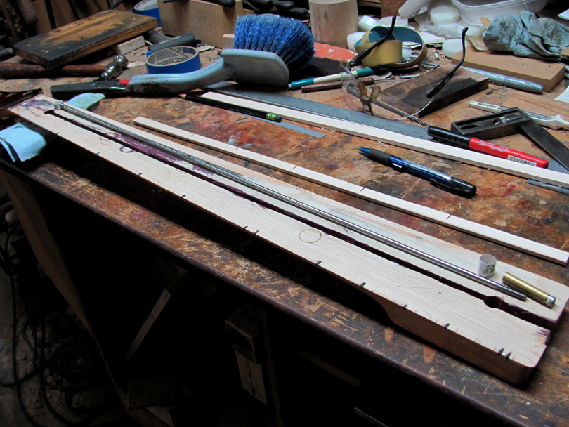
Here's the new truss rod, ready to be installed:
IMG_0602B.jpg


I decided to go with a SASR Embedded design truss rod for the Roscoe. Single Acting, Single Rod, fully embedded in epoxy. I developed this design truss rod around 1994 and used it all of my basses up to about 2006. Plus about 400 necks for other Luthiers. It's fairly simple to build and install, and it'll fit into the Roscoe with hardly any modifications.

In 2006, I developed the Double-Acting version of this design, and that's what I've been using on most of my basses since then. I could have fit the DASR into this Roscoe neck but, after talking with the owner, we decided to stay with the Single Acting version. Less routing and modification to the neck. The original truss rod was Single Acting. I think there's about zero chance that this neck will backbow and need a reverse truss rod push.

The reason I went with a Single Rod design was to get the most mechanical ratio that I could, within the thickness of the neck. This Roscoe is a thin neck, and the slot for the truss rod was about 0.480" deep in the center. I didn't dare to cut it any deeper, because it was already thin to the back. I usually like to have the slot about 0.520" deep to get the preferred 0.180" of droop (curvature of the rod). This installation will end up at about 0.160" of droop, the best I could do. It will certainly be a lot more powerful than the original truss rod.

IMG_0601B.jpg


Here's what the hardware looks like at the heel end. The rod is 3/16" 304 stainless, threaded 10-32. The adjusting nut is 5/16" dia 360 brass bar stock, drilled and threaded 10-32 all the way through. The head is a stainless 10-32 x 1/4" Socket Head Cap Screw, screwed into the outer end. It's not in the picture, but I then drill a 2mm hole crosswise through the brass, right behind the head of the screw, and press in a 2mm stainless pin. That locks the head to the brass barrel. The socket head takes a 5/32" Allen wrench, and is nearly impossible to strip out.

I call the aluminum part the Slug. It's a slice of 1/2" dia 6061 aluminum bar stock, 1/2" long. A #7 hole is drilled through up near the top, angled down at 2 degrees. I use a small counterboring bit to make that recessed spot face on it.

These parts can be made without big machines.
IMG_0604B.jpg


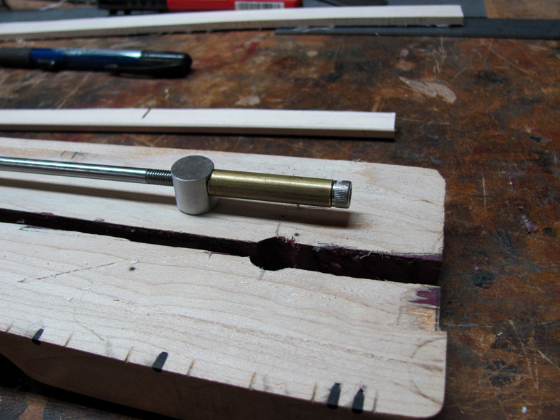
Here's how the adjusting end goes together. The end of the nut presses on that counterbore in the slug as it pulls the rod through it. The slug transfers the load to the wood.

IMG_0605B.jpg


And this is how it fits in place, ready for the epoxy pour. The slug fits down in its hole, top flush with the surface. The adjusting nut is also just flush with the surface, tilted at that 2 degree angle. I only had to slightly enlarge that trough in the neck with a file to get the new nut to fit. I've waxed the outside of the nut and packed the socket head full of wax, then sealed up the back of the heel with masking tape.
IMG_0603B.jpg


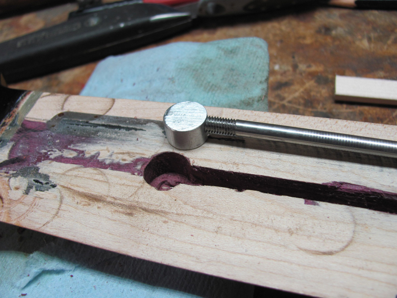
At the other end is my standard design for single-rod anchors. A slice of 1/2" dia aluminum. 3/8" long. I drill and tap a 10-32 thread through it, at the 2 degree angle. This end of the rod is also threaded, but it's permanently locked into the anchor by a 2mm stainless pin. The rod does not rotate in my Single Rod designs.

IMG_0606B.jpg


And that's how the anchor end fits in, top flush with the surface, positioning the end of the rod up at the surface, aiming down into the slot at a 2 degree angle.
IMG_0600B.jpg


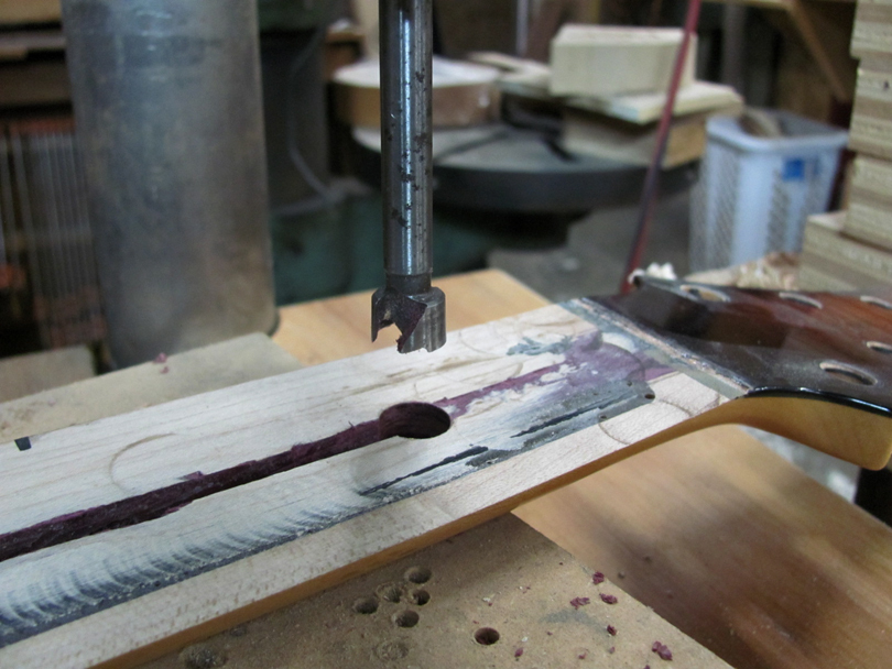
And here's why I like using 1/2" round aluminum stock for the anchor and the slug: It's real easy to make the pockets in the neck with a 1/2" Forstner bit. No special routing needed.

In the next post, I'll epoxy it in.
 
Finishing up the new custom truss rod installation in the Roscoe:

IMG_0608B.jpg


I didn't get any pictures of the last preparation before the glue up, but here's what I did:

I made up a maple filler strip that's a nice sliding fit into the slot. Sawed notches into the top edge so it can flex to the droop shape. I cleaned out the rest of the silicone sealer goop from the slot and test-fitted all the parts. Wiped the whole truss rod with wax, except for the anchor. No wax on the Slug. A dab of wheel bearing grease in the threads of the adjusting nut. Waxed the outside of the adjusting nut, and packed the socket head full of wax.

I assembled the whole truss rod down into the slot, with the adjusting nut threaded on, just lightly touching the Slug. Put masking tape over the heel to hold back the epoxy. Double check everything for fit. Then I mixed up the epoxy (West Systems 105/205) and gently poured it into the slot, flowing around the truss rod. I filled the slot about halfway full.

Set the filler strip in place in the slot, on top of the truss rod, and start applying clamps. The clamps, particularly the one in the center, push the filler strip down, and push the truss rod down until I can feel it contact the bottom of the slot. This is really important, to form the truss rod into the Droop Curve.

Also, notice how I've put pieces of stiff cardboard under the neck in the center. This is to prevent the clamps from pushing the neck into a forward bow while the epoxy cures. We don't want that.

The two ends of the rod are held up at the surface by the anchor and the Slug. The center is pushed down tight against the bottom of the slot. All the remaining space under and around the rod is filled solid with hard epoxy. There are no air gaps inside the neck, and nothing can rattle or buzz. The epoxy and the filler strip form a snug curved channel for the rod to press against as it's tightened. This is how an Embedded Single Rod truss rod works.

Because the length of the rod is smooth and waxed, it doesn't bond to the epoxy "sleeve" around it. The first time you tighten up an Embedded truss rod, you hear a cracking sound down inside the neck, which can be a bit startling. That's the rod breaking free within the epoxy. Once the rod is "cracked free", it can slide a small amount within the epoxy sleeve. It needs to be able to do that to bend the neck.

Anyway, there's the Roscoe, with its new truss rod clamped up and curing.


IMG_0607B.jpg


At the adjusting nut, I pour the trough full of epoxy, up to and slightly above the surface. Like the rod, the adjusting nut is completely surrounded by a sleeve of hard epoxy. No air gaps, no rattle. But it's waxed, so it will break free and be able to turn within the epoxy sleeve.

IMG_0609B.jpg


The anchor end is also filled up with epoxy. I added a bit more after taking this picture.

IMG_0610B.jpg


I let it cure overnight and unclamped it.

IMG_0611B.jpg


IMG_0612B.jpg


A few minutes on the edge sander to trim the filler strip and excess epoxy down to flush with the surface. Gently, carefully.

IMG_0613B.jpg


And there's the truss rod installation, complete! The Roscoe is ready to go back to Dr Freekmagnet for its new fingerboard.

IMG_0614B.jpg


I pulled the tape off of the heel, and cleaned the wax out of the socket. Cracked the adjusting nut loose with a 5/32 Allen wrench, and backed it out. Just to make sure it's free and functional.

IMG_0615B.jpg


Here's the adjusting nut removed. The epoxy has filled the trough completely, leaving a snug fitting hole for the adjusting nut.

That's a quick look at how an Embedded Single Rod truss rod is made and installed. Later in this thread, when I get to it, I'll show the design and process in more detail. Both Single Acting and Double Acting versions.
 
Last edited:
For your reference, another example of a custom-made truss rod to repair an existing neck:

This is for a Fender P-Bass Lyte neck, one of those fairly rare ones made in Japan with the unique heel. This one had a sheared-off truss rod and the owner sent it to our shop for repair. Jeremy (Dr Freekmagnet) is handling most of the surgery. I made up the parts for the replacement truss rod.

This is a skunk-stripe style neck, and the truss rod is extracted and replaced from the back, through the skunk stripe slot. I did the same job on a similar Lyte neck a few years ago, and documented the whole process on this thread:

https://www.talkbass.com/threads/ne...ss-rod-in-a-fender-skunk-stripe-neck.1572369/

Here's the truss rod kit I made up for this one, a few days ago:

IMG_0664B.jpg


The original P-Lyte truss rod was metric, using 5mm mild steel rod and 5mm x 0.8 threads. I made the new rod in my standard size, 3/16" 304 stainless rod, with US 10-32 threads. The 3/16" rod is about 0.010" smaller in diameter than 5mm rod, so it slipped easily into the slot and the hole at the headstock.

IMG_0662B.jpg


I made the new barrel nut to my usual design, using 5/16" brass round stock, drilled and threaded 10-32 all the way through. The head is a stainless 10-32 x 1/4" Socket Head Cap Screw. It's threaded into the brass barrel and permanently locked with a 2mm stainless cross pin. Then the whole OD of the barrel nut is turned down about 0.010" to match the diameter of the original barrel nut.

You can see that I made the new barrel nut about 1/4" longer than the original. This brings the head with the hex socket out to even with the elliptical opening in the headstock. Neater looking, and allowed some extra length of engaged threads inside the nut.

IMG_0663B.jpg


The anchor on P-Lytes is unique, completely different from US or Mexican Fender necks. It's a round cylinder with milled flats on the side, T-shaped from the end. It fits down into a CNC-cut pocket in the neck. The original anchor was mild steel. The rod went through it and was welded on the end.

I machined up the new anchor from aluminum and drilled and threaded it 10-32. the rod threads into it and is locked with another of those little 2mm pins. The rod goes through the anchor at a 2 degree angle, to fit it to the correct droop curve.

IMG_0665B.jpg


You may be wondering why there is a second threaded hole. So am I. In a moment of Vertical Dyslexia, I drilled and tapped the hole at the wrong place in the anchor. Forgetting that we are working from the bottom side of the neck. Oops. Oh, well, there's plenty of space for the correct hole at the bottom/top end.

Jeremy's got the truss rod glued in the neck now, under a fresh walnut skunk stripe. No harm to the maple of the neck or the fingerboard or frets.

We thought about embedding it in epoxy, but decided not to. It's installed about like it was originally, with LMII glue holding in the skunk stripe. A few drops of glue in the slot around the rod, to make sure it doesn't rattle.

The rebuilt neck is very close to original in appearance and performance, except the adjustment is with a US 5/32 Allen wrench.

Most of you could make up a truss rod like this with bench tools. Yeah, I used a milling machine and lathe to go faster, but you could make this anchor and barrel nut with a drill press, hacksaw and files. They are small parts.
 
For your reference, another example of a custom-made truss rod to repair an existing neck:

This is for a Fender P-Bass Lyte neck, one of those fairly rare ones made in Japan with the unique heel. This one had a sheared-off truss rod and the owner sent it to our shop for repair. Jeremy (Dr Freekmagnet) is handling most of the surgery. I made up the parts for the replacement truss rod.

I would be remiss if the patient didn't drop by to say, "Thanks" to you and freekmagnet for this job - and all the other luthiers who help us restore these great instruments, instead of just replacing them.

The Lyte is not a high end bass by any means, but the result is very much appreciated by me and those who will hear this restoration!

Seriously, this is akin to magic in my eyes! Rock on and please keep spreading the experience, so someone will be around to fix my basses forever!
 

Attachments

  • PXL_20240917_042157747~2.jpg
    PXL_20240917_042157747~2.jpg
    2 MB · Views: 36
  • PXL_20240917_042216781.jpg
    PXL_20240917_042216781.jpg
    1.6 MB · Views: 35
I've read through this thread a number of times in anticipation of my first build, I really appreciate the knowledge being freely shared here @Bruce Johnson ! I am planning for a DASR design. A question for @MPU or Bruce, how long of threaded brass piece are you using on either side of adjusting end block and why those lengths (and bolt length...)? Why not have the bolt press up against the block, then go into the next threaded brass piece?
 

Attachments

  • Screenshot 2025-01-15 160120.jpg
    Screenshot 2025-01-15 160120.jpg
    84.4 KB · Views: 36
I've read through this thread a number of times in anticipation of my first build, I really appreciate the knowledge being freely shared here @Bruce Johnson ! I am planning for a DASR design. A question for @MPU or Bruce, how long of threaded brass piece are you using on either side of adjusting end block and why those lengths (and bolt length...)? Why not have the bolt press up against the block, then go into the next threaded brass piece?

Hello dazmond;

Sure, those are easy questions. I call the rear section with the threads the Barrel. On almost all of my truss rod versions, I make it 1.25" long. The sawn-off bolt sticks into the forward end of the Barrel about 1/4", and is cross pinned with that little 2mm stainless pin. The back end of the Barrel is threaded 10-32 to about 1" deep. The #21 pilot hole for the threads goes all the way through the Barrel. The 1/4" dia hole in the front of the Barrel is drilled 3/8" deep.

When the truss rod is installed in the neck, the rod threads 1/2" deep into the Barrel. That's important to make sure the brass threads have enough strength under load. When you lay out the length of the rod and the position of the rear anchor, make it so there's 1/2" of thread engagement.

The CrossBar is aluminum bar that goes crosswise, and the Sleeve is the round tube-like spacer between the head of the sawn-off bolt and the CrossBar. On my standard model DATR rods, I make the Spacer 3/4" long. Some versions get a Spacer that's 1" or even 1 1/8" long.

The reason for the Sleeve is to space the CrossBar back away from the end of the neck. The CrossBar is the part that applies the load to the wood of the neck. Tightening the truss rod in the normal direction, the back faces of the two ends of the CrossBar are pushing inward, pressing hard against the wood. Tightening the truss rod in reverse, the front faces of the CrossBar are pushing outward with a lot of force. If you used no Sleeve and mounted the CrossBar right up about at the nut, it would have nothing to push against. As you tightened in reverse, the CrossBar would just break out of the end of the neck.

The Crossbar is normally located about 3/4" inboard from the end of the neck, to make sure there's enough wood structure for it to push against. And the reason for the Sleeve and the the extended length of the bolt is to get the head out where it can be easily engaged with a wrench.

This applies for both headstock-adjust and heel-adjust installations. If the adjusting head is at the heel, you need to locate the CrossBar back at least 3/4" from the end of the heel, to make sure there's enough wood structure for it to push against. When it's tightened in reverse.
 
Thanks again, Bruce. That makes sense, and is kind of what I figured, but wanted to make sure I was understanding completely. One more thing to clarify, the barrel end that takes the tip of the 1/4" bolt and cross pin, do you tap that portion as well? Or is it just a slightly bigger smooth hole until the threads for the actual rod start? Too bad something like this has to be ordered in such big quantities:
 
Thanks again, Bruce. That makes sense, and is kind of what I figured, but wanted to make sure I was understanding completely. One more thing to clarify, the barrel end that takes the tip of the 1/4" bolt and cross pin, do you tap that portion as well? Or is it just a slightly bigger smooth hole until the threads for the actual rod start? Too bad something like this has to be ordered in such big quantities:

Hello dazmond;

It's just a straight 1/4" hole in the barrel, about 3/8" deep. The cutoff bolt goes through the Sleeve and the Cross Bar and plugs into the end of the Barrel, about 1/4" deep. Then I clamp the assembly in a vise and drill a tiny 2mm hole crosswise through the barrel and the bolt, and tap in a little 2mm dia x 10mm long stainless dowel pin.

IMG_1550B.jpg


Here's an old picture from 2007 of one of the early prototypes. The bolt is a 1/4-20 x 3" Socket Head Cap Screw, sawn off to 1 1/2" long under the head.

IMG_4118B.jpg


Here's a 2015 picture of some, where I've switched to Stainless Socket head Cap Screws, and 6061 aluminum for the sleeves. That's the standard configuration that I make up for most installations. The sleeve is 3/4" long and the bolt is cut to 1 1/2".

On some installations, I extend the head out further, making the sleeve 1" or 1 1/8". I've also started making the sleeve from 3/8" square aluminum for some. And I also make the Spoke Wheel versions. But the back half of the cross bar and the barrel remains the same.


For your entertainment and imagination, here's another variation of the DATR head assembly, combining the Cross Bar and the Sleeve into one solid brass block.

IMG_0992B.jpg


IMG_0993B.jpg


IMG_0996B.jpg


IMG_1005B.jpg


This is the truss rod that goes into the underside of the fingerboard to go on an Ampeg Baby Bass. It adjusts the overhanging end. This is a 1/4" dia stainless rod. The heavy brass block at the end is intentional. It really improves the clarity of the notes played up there at the end.
 
The sawn-off bolt sticks into the forward end of the Barrel about 1/4", and is cross pinned with that little 2mm stainless pin. The back end of the Barrel is threaded 10-32 to about 1" deep. The #21 pilot hole for the threads goes all the way through the Barrel. The 1/4" dia hole in the front of the Barrel is drilled 3/8" deep.

Is there a reason for not keeping Barrel fully threaded?

Wdyt about the following:
- Keep Barrel fully threaded with #10-32
- Use #10 bolt instead 1/4" one
- Cut #10 bolt at desired length, keeping 1/4" of threads to engage the Barrel
- Install 2mm pin

My assumptions are that #10 bolt will be strong enough to turn #10 rod and that 1/4" threaded part is doing no work (pin does).

I'm concerned that drilling concentric holes from other side would be hard to manufacture with drill press alone.
 
Is there a reason for not keeping Barrel fully threaded?

Wdyt about the following:
- Keep Barrel fully threaded with #10-32
- Use #10 bolt instead 1/4" one
- Cut #10 bolt at desired length, keeping 1/4" of threads to engage the Barrel
- Install 2mm pin

My assumptions are that #10 bolt will be strong enough to turn #10 rod and that 1/4" threaded part is doing no work (pin does).

I'm concerned that drilling concentric holes from other side would be hard to manufacture with drill press alone.

Hello joover;

That's a valid question. The reason I don't generally recommend using a 10-32 bolt for the front half, is that it creates a new weakest point in the assembly; the spot that will break first at the lowest torque. and the lowest tensile load.

The weakest part of the truss rod overall is the threaded part of the rod. Down in the roots of the thread is the smallest diameter, and the smallest cross-sectional area. As you twist the rod and apply torque to it, that's the spot where it will shear off first. That's true of almost all truss rods; they break right in the threads.

If you take that steel rod with 10-32 threads and drill a hole down through it cross-wise, for a 2mm pin, that reduces the cross-sectional area even more. Like 40%.

In single-rod designs, the Barrel is not applying much torque to the rod. It doesn't rotate the rod. The threads are turning on each other and transferring most of the load axially; pulling or pushing.

But, if you use a 10-32 bolt at the front of the assembly, locking it to the barrel with threads and a cross pin, that will become the weak spot. Too much torque and it will shear off right at the pin hole.

That's why I went with a 1/4" bolt on the front, connecting it to the Barrel with a straight hole and the cross pin. More cross-sectional area and torque capacity than the threads on the rod.

A bonus to using the 1/4" bolt is that it has a larger head that uses a 3/16" Allen wrench. Nearly impossible to round out or strip out.
 
Last edited:
For your reference, here's the DASR Embedded truss rod kit to go into a '70's Fender Jazz neck. It's here for a full rebuild in the hands of Dr Freekmagnet. This is the configuration that we put in most Fender and Fender-like necks.

IMG_0899B.jpg


Here's the rod kit sitting on top of the neck, checking the length. The fingerboard has been routed off the neck, and we'll be ripping out the old truss rod soon. The rod will fit into the original curved slot, with a little bit of new routing for the head assembly in the heel, and for the anchor. It will be fully cast in place in epoxy.

IMG_0900B.jpg


This is the configuration of the adjusting head that we use in most heel-access necks. The stainless 1/4" socket head, 3/8" square aluminum Sleeve, 3/8" square Cross Barr with straight-cut ends, and the standard brass barrel. The head ends up flush with the heel.

IMG_0901B.jpg


The anchor is 3/8" dia x 3/8" high aluminum. It ends up installed on that line.

I'll post some more pictures as we get it installed.
 
And here are three DASR Embedded Truss Rods with Spoke Wheel adjusting heads. They are installed in 5-piece laminated flame maple/purpleheart neck-through blanks for my buddy Bill Asher. These will become 34" scale 6-string basses in his Wolf series. Bill's been using my truss rods in most of his guitars and basses for a while. On some models, I send him the kits and he installs them. On others, he sends me the neck blanks and I put the truss rods in.

IMG_0902B.jpg


Here's the routing fixture setup that I use for routing the curved slot in the blank. The lower part of the fixture holds the neck blank solidly with the top surface. The upper part guides the router straight down the center, and the side curved rails control the depth of the slot to get the correct Droop curve. I explained all this a few pages back.

IMG_0903B.jpg


Here's the router for cutting the slot. It's a spiral carbide 1/4" bit. The base has a 1 1/2" aluminum collar that slides in the fixture.

IMG_0904B.jpg


There's the slot, fully routed.

IMG_0905B.jpg


This block of MDF is used as a gauge to set the neck blank up flush with the tops of the rails in the fixture.

IMG_0906B.jpg


Before I cut the slot, I used this routing template to rout the pockets for the adjuster head and the anchor. This template also clamps down on top of the fixture. I do the pockets with a plunge router with a 1/4" bit and a 1" collar.

IMG_0907B.jpg


Bill also had me rout the top surface of the Tang, offset 1/8" down, and with a small neck angle.

IMG_0912B.jpg


Here's the adjusting head assembly. Standard configuration for a DASR, except with the spoke wheel head. I had to rout that small extra pocket for the spoke wheel head to fit into.

IMG_0913B.jpg


All the parts, ready to install. The truss rod, the adjusting head assembly, 4 strands of carbon fiber TOW, and the maple filler strip.

IMG_0914B.jpg


For these bass necks, I used the larger 5/8" dia x 3/8" deep aluminum anchors. Threaded onto the rod, at the 2 degree angle, with the stainless pin at the back.

IMG_0915B.jpg


Starting the installation. The parts are waxed. I pour a bead of West Systems 105/205 epoxy down in the slot and press the carbon fiber TOW strands down into it. This forms the Backstrap under the truss rod. It extends from the heel out to the 5th fret, not the full length of the neck.

IMG_0916B.jpg


Before installing the adjusting head, I put a blob of woodworking glue down in the slot that the square Sleeve fits into.......

IMG_0917B.jpg


Then, with the adjusting head installed, I add some more woodworking glue to the top of the sleeve, pushing it down into the small gaps at the sides. This creates a seal that prevents the epoxy from flowing up and getting in around the spoke wheel head.

With the truss rod in place, I add some more epoxy into the slot, and slip the maple filler strip down into it, on top of the rod.

IMG_0918B.jpg


Then over to the clamping bench. The clamps push the filler strip down, seating the truss rod into the curved slot.

IMG_0919B.jpg


The completed installation, after the filler strip and excess epoxy are trimmed off flush. The fingerboard will end up seating right against the spoke wheel head. A nice neat installation.

IMG_0920B.jpg


And there are the three neck blanks, truss rods installed, ready to go back to Bill.
 
View attachment 7174959

Here's the routing fixture setup that I use for routing the curved slot in the blank. The lower part of the fixture holds the neck blank solidly with the top surface. The upper part guides the router straight down the center, and the side curved rails control the depth of the slot to get the correct Droop curve.
I was just getting ready to ask how you approached routing the curved truss rod slot but you were a step ahead of me!