
As for it "remembering" where it was bent, do be aware that you have to overcorrect to deal with springback to get it straight, once bent. i.e. if you bend it, then press it against a flat surface, it will never get to straight. You have to bend it slightly past straight, so that it springs back to straight when you stop bending it. Not terribly difficult, but there's a bit of art involved.

Enjoy the benefits of a premium membership!
Upgrade Account
-
TalkBass has been independent since 1998. Add your voice.
Create a free account to reply to discussions, view embedded media, and browse with fewer display ads.
Join free Log in
Want zero display ads or expanded classifieds tools? Compare plans.
You are using an out of date browser. It may not display this or other websites correctly.
You should upgrade or use an alternative browser.
You should upgrade or use an alternative browser.
Building Your Own Custom Truss Rods
- Thread starter Bruce Johnson
- Start date
More options
Who Replied?

Well, I've been busy on many other things.......but I need to continue on with the main story of this thread. That is, how to build your own custom truss rods.
I've got a job here on my bench for a DADR truss rod, a replacement for a Pedulla. A one-off. It'll be pretty much identical to the one I showed on Page 4, Post #77. But I'll document the whole process of building it in detail, for any of you who haven't worked it out for yourselves.
The first topic to get back to is: How to cut threads on a stainless rod and not have them get Wonky. We don't want Wonky threads around here.

Here's the Secret Magic Tool for preventing Wonky threads. It's a custom-made die holder/handle.........

...With an extended nose on the back side that has a guide bushing for 3/16" rod stock. This guide bushing holds the die square with the rod as you turn it, so the threads are cut square. To me, this is an obvious solution for cutting threads on rod stock. But I couldn't find anyone who makes or sells a die handle like this.
So, I made my own. I've been using it for about 27 years, on every truss rod I've made. Several thousand of them. I've got a machine shop, with mills and lathes, so I made it from metal. The center hub is aluminum, the arms are steel, and the rubber knobs on the ends are commercial parts. It's been a workhorse.
I realize that most of you don't have mills and lathes (yet), but you need a tool like this to put nice threads on truss rods.
I decided, as an experiment, to see if I could make up a Die Handle With Guide Bushing, from......... maple. Why not? Using only a drill press, bandsaw, and edge sander. Most of you should be able to make one or two of these for yourself.

Here's a suitable chunk of hard maple from my cutoffs shelf, 1 1/4" thick x 3" wide x about 18" long. Above it is the 10-32 Left Hand die.
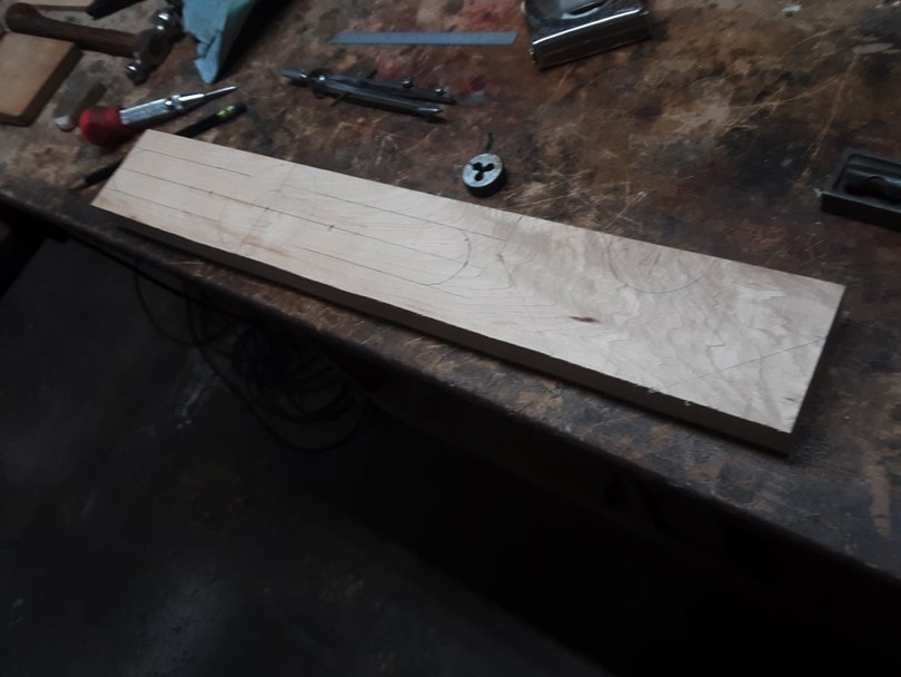
Here's the layout on the board. There's two parts, the flat handle and the guide block that attaches underneath. I made the handle 12" long.

Most standard dies are round, 1" diameter. I used a 1" Forstner bit to cut a shoulder 3/8" deep, and then a 7/8" Forstner bit to drill the rest of the way through.

All dies have two or three dimples around their outer edge. Standard die handles have two or three small horizontal machine screws that are tightened into the dimples, to keep the die from rotating in the handle. This particular one has only two dimples, so I installed two 10-32 machine screws, in from either side, to do the locking. I drilled the holes #21, standard tap drill size, and cut the threads with a 10-32 tap. Tapped threads in maple are surprisingly strong.
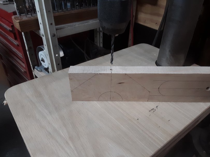
In the guide block part, I drilled a 13/64" hole down through. Slightly larger than the 3/16" rod size.
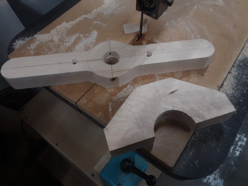
Cut the parts out on the bandsaw.........

Cleaned up the edges on the edge sander and spindle sander. Small bevels all around. Not perfect, but this is a working tool, which is going to get oily. You could shape the handle with finger notches, if you really wanted to.....
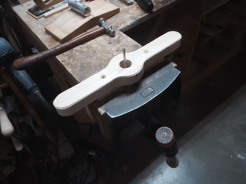
The guide block is clamped in the vise. I used a piece of 3/16" rod stock as a guide to line it up with the bore in the handle......and screwed the handle to the guide block.
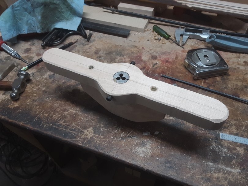
And here it is, finished! The die is tapped down into the bore, aligning the dimples with the machine screws. I ground slight cones onto the tips of the two 10-32 socket head screws, and tightened them into the dimples.

The big half-round notch in the guide block is to let the chips come out the back of the die.
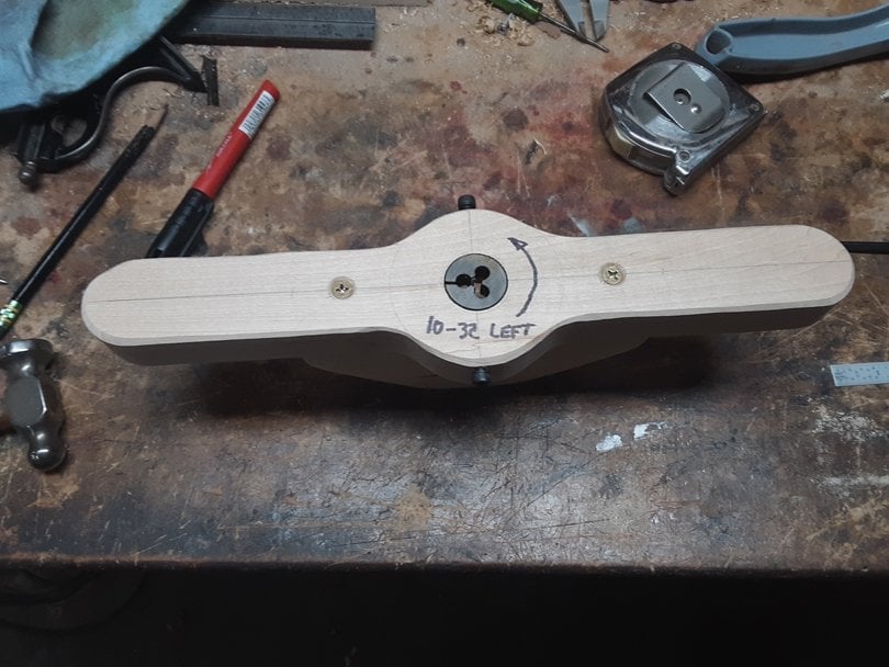
I made this Die Handle specifically to hold my 10-32 Left Hand die, for cutting the left hand threads on a DADR-style truss rod. Which I don't make up very often. I plan to always keep the LH die in it, and I clearly marked it. So I remember which way to turn it.
This took me a little less than an hour to make up.
If you are tooling up to make your own DADR truss rods, make up two of these. One for 10-32 RH and one for 10-32 LH. And mark them.
Coming up.....I'll show it in use!
I've got a job here on my bench for a DADR truss rod, a replacement for a Pedulla. A one-off. It'll be pretty much identical to the one I showed on Page 4, Post #77. But I'll document the whole process of building it in detail, for any of you who haven't worked it out for yourselves.
The first topic to get back to is: How to cut threads on a stainless rod and not have them get Wonky. We don't want Wonky threads around here.
Here's the Secret Magic Tool for preventing Wonky threads. It's a custom-made die holder/handle.........
...With an extended nose on the back side that has a guide bushing for 3/16" rod stock. This guide bushing holds the die square with the rod as you turn it, so the threads are cut square. To me, this is an obvious solution for cutting threads on rod stock. But I couldn't find anyone who makes or sells a die handle like this.
So, I made my own. I've been using it for about 27 years, on every truss rod I've made. Several thousand of them. I've got a machine shop, with mills and lathes, so I made it from metal. The center hub is aluminum, the arms are steel, and the rubber knobs on the ends are commercial parts. It's been a workhorse.
I realize that most of you don't have mills and lathes (yet), but you need a tool like this to put nice threads on truss rods.
I decided, as an experiment, to see if I could make up a Die Handle With Guide Bushing, from......... maple. Why not? Using only a drill press, bandsaw, and edge sander. Most of you should be able to make one or two of these for yourself.
Here's a suitable chunk of hard maple from my cutoffs shelf, 1 1/4" thick x 3" wide x about 18" long. Above it is the 10-32 Left Hand die.
Here's the layout on the board. There's two parts, the flat handle and the guide block that attaches underneath. I made the handle 12" long.
Most standard dies are round, 1" diameter. I used a 1" Forstner bit to cut a shoulder 3/8" deep, and then a 7/8" Forstner bit to drill the rest of the way through.
All dies have two or three dimples around their outer edge. Standard die handles have two or three small horizontal machine screws that are tightened into the dimples, to keep the die from rotating in the handle. This particular one has only two dimples, so I installed two 10-32 machine screws, in from either side, to do the locking. I drilled the holes #21, standard tap drill size, and cut the threads with a 10-32 tap. Tapped threads in maple are surprisingly strong.
In the guide block part, I drilled a 13/64" hole down through. Slightly larger than the 3/16" rod size.
Cut the parts out on the bandsaw.........
Cleaned up the edges on the edge sander and spindle sander. Small bevels all around. Not perfect, but this is a working tool, which is going to get oily. You could shape the handle with finger notches, if you really wanted to.....
The guide block is clamped in the vise. I used a piece of 3/16" rod stock as a guide to line it up with the bore in the handle......and screwed the handle to the guide block.
And here it is, finished! The die is tapped down into the bore, aligning the dimples with the machine screws. I ground slight cones onto the tips of the two 10-32 socket head screws, and tightened them into the dimples.
The big half-round notch in the guide block is to let the chips come out the back of the die.
I made this Die Handle specifically to hold my 10-32 Left Hand die, for cutting the left hand threads on a DADR-style truss rod. Which I don't make up very often. I plan to always keep the LH die in it, and I clearly marked it. So I remember which way to turn it.
This took me a little less than an hour to make up.
If you are tooling up to make your own DADR truss rods, make up two of these. One for 10-32 RH and one for 10-32 LH. And mark them.
Coming up.....I'll show it in use!
Last edited:
Another way to make one of these special die handles is to buy a commercial die handle, like this......
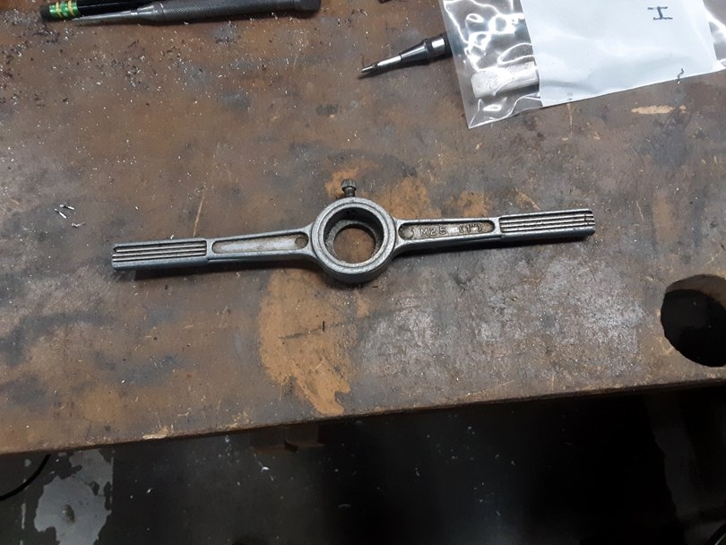
...And then attach a maple guide block to the back of it. Two screws through the handle, or something.....
Here's the process for putting 10-32 threads on the end of a 3/16" 304 stainless steel rod:
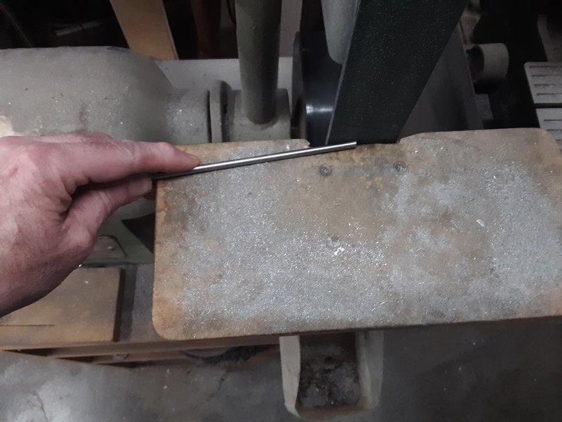
The first step is to grind a shallow angle bevel on the end of the rod. I hold it against the belt of my Knife Belt Sander at about this angle, and roll it around. The bevel isn't 45 degrees; it needs to be a shallow angle, like 10-20 degrees.
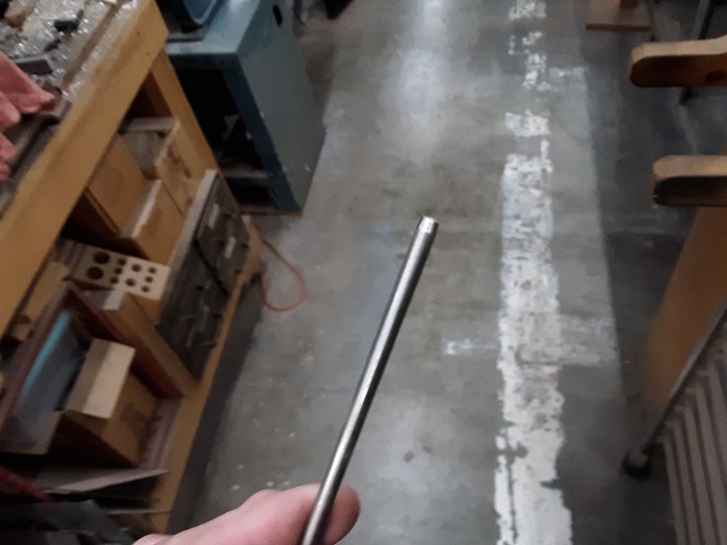
Like this. It's very difficult to get the die started if you don't grind this bevel cone first. It doesn't have to be perfect, but try to get it reasonably round and symmetrical.....
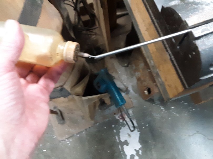
Then clamp the rod tightly in a machinist's vise. About as tight as you can. It takes a surprising amount of torque to cut 10-32 threads in stainless. And an equally surprisingly amount of clamping force to hold a small stainless rod still.
Put a drop of thread-cutting oil on the cone end. Regular cutting oil or motor oil will work, but thread-cutting oil like TapMatic is better.
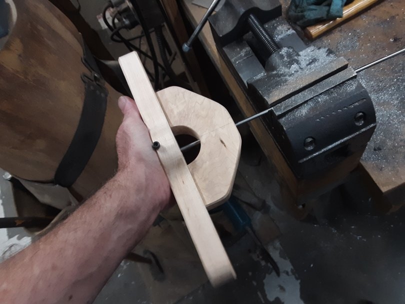
Slip the cool Die Handle With Guide Block onto the rod, bringing the ground cone end into the end of the die.
I didn't mention it before, but if you look close at the die, one side has a tapered cone ground into the cutting teeth. It's usually the side opposite the side with the etched lettering. The side with the cone should be toward the guide block of the handle. The cone in the die should engage with the cone that you ground on the end of the rod.
You have to push pretty hard on the face of the handle, like this, while you turn it the first 1/4 turn. You'll feel the teeth dig into the cone on the rod.
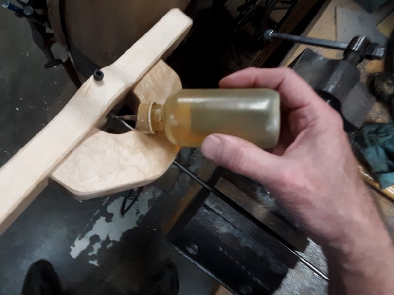
Now, add another drop to the back side of the die, right where the teeth are cutting. And another drop or two on the rod. You don't need to flood it with oil, just a few drops.
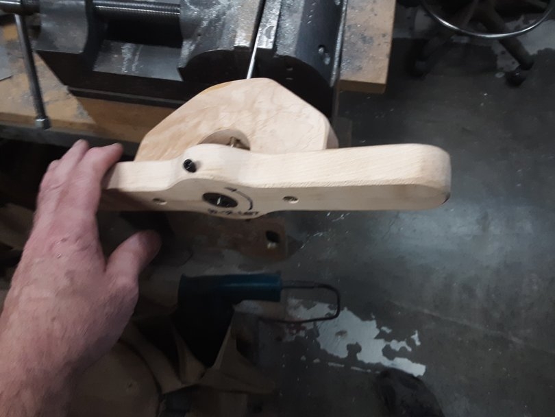
Start turning the handle, cutting the threads. Slowly. Like 30 rpm, which is 2 seconds per full turn. Slow speed is really important when cutting stainless. If you take it up to 60 rpm, 1 second per full turn, it'll start chattering and jamming. If you keep pushing it, it can lock up and literally break the teeth of the die.
If you keep it slow, with a few drops of oil, you should be able to cut the threads all the way in one continuous turning motion. If it wants to lock up, stop, and back up 1/4 turn. Add a drop of oil, and then continue forward. Patience. Stainless has to be cut slowly.
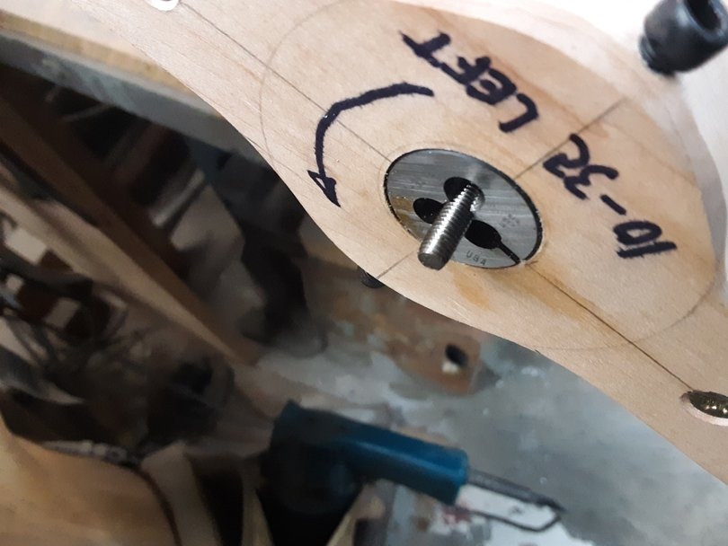
As you are cutting the threads, watch the end of the rod coming out the front side of the die. The length of threads cut will be that distance, plus 3/8", the thickness of the die.
When you've cut the threads as far as you want, stop. Put a drop of oil on the threads sticking out of the front of the die. Before you reverse direction and turn the die off of the rod. This is important. If you back the die off the threads, dry, it may jam and damage the threads.
That's the process.
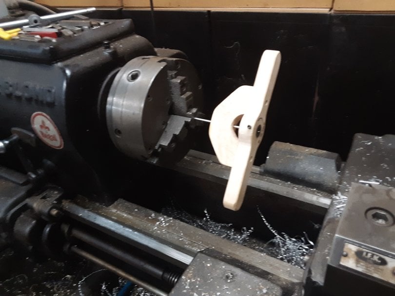
I normally cut the threads by power, using my big LeBlond lathe. 30 rpm, really slow. That 10" chuck can grip the rod with about a ton of force. I hold one of the handles while it's cutting, and let go when the threads reach the full length. Then I stop the lathe, add the drop of oil, and hand turn the die off the rod.
...And then attach a maple guide block to the back of it. Two screws through the handle, or something.....
Here's the process for putting 10-32 threads on the end of a 3/16" 304 stainless steel rod:
The first step is to grind a shallow angle bevel on the end of the rod. I hold it against the belt of my Knife Belt Sander at about this angle, and roll it around. The bevel isn't 45 degrees; it needs to be a shallow angle, like 10-20 degrees.
Like this. It's very difficult to get the die started if you don't grind this bevel cone first. It doesn't have to be perfect, but try to get it reasonably round and symmetrical.....
Then clamp the rod tightly in a machinist's vise. About as tight as you can. It takes a surprising amount of torque to cut 10-32 threads in stainless. And an equally surprisingly amount of clamping force to hold a small stainless rod still.
Put a drop of thread-cutting oil on the cone end. Regular cutting oil or motor oil will work, but thread-cutting oil like TapMatic is better.
Slip the cool Die Handle With Guide Block onto the rod, bringing the ground cone end into the end of the die.
I didn't mention it before, but if you look close at the die, one side has a tapered cone ground into the cutting teeth. It's usually the side opposite the side with the etched lettering. The side with the cone should be toward the guide block of the handle. The cone in the die should engage with the cone that you ground on the end of the rod.
You have to push pretty hard on the face of the handle, like this, while you turn it the first 1/4 turn. You'll feel the teeth dig into the cone on the rod.
Now, add another drop to the back side of the die, right where the teeth are cutting. And another drop or two on the rod. You don't need to flood it with oil, just a few drops.
Start turning the handle, cutting the threads. Slowly. Like 30 rpm, which is 2 seconds per full turn. Slow speed is really important when cutting stainless. If you take it up to 60 rpm, 1 second per full turn, it'll start chattering and jamming. If you keep pushing it, it can lock up and literally break the teeth of the die.
If you keep it slow, with a few drops of oil, you should be able to cut the threads all the way in one continuous turning motion. If it wants to lock up, stop, and back up 1/4 turn. Add a drop of oil, and then continue forward. Patience. Stainless has to be cut slowly.
As you are cutting the threads, watch the end of the rod coming out the front side of the die. The length of threads cut will be that distance, plus 3/8", the thickness of the die.
When you've cut the threads as far as you want, stop. Put a drop of oil on the threads sticking out of the front of the die. Before you reverse direction and turn the die off of the rod. This is important. If you back the die off the threads, dry, it may jam and damage the threads.
That's the process.
I normally cut the threads by power, using my big LeBlond lathe. 30 rpm, really slow. That 10" chuck can grip the rod with about a ton of force. I hold one of the handles while it's cutting, and let go when the threads reach the full length. Then I stop the lathe, add the drop of oil, and hand turn the die off the rod.
Last edited:
Here's a quick overview of the process for making one of the DADR truss rods that I showed in the first few pages of this thread. I'm making up a custom size DADR rod to fit into a Pedulla neck that Jeremy is rebuilding for a customer. Yep, it had the classic sheared-off little square end of its original truss rod.
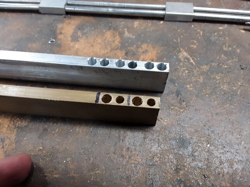
The process starts with making up the blocks. I make both the brass and aluminum blocks from 1/4" x 3/4" bar stock. The brass is 360 alloy and the aluminum is 6061 alloy. I get it online, shipped to me, from Onlinemetals.com.
I stand the bar stock up on edge and lay out the locations of the holes for the 5 blocks. If I were making up a batch of these truss rods, I might set up and drill these holes in a milling machine. But for a one-off, it's faster to do a hand layout and drill the holes in a drill press. And that's how any of you can do it, if you don't have a milling machine (yet).
On the brass bar, the 1st and 3rd holes are drilled #21, which is the tap drill size for threading 10-32. The 2nd and 4th holes, and all the holes in the aluminum bar, are drilled #12, for a sliding fit on the 3/16" rod.
In the layout, the 1st hole (from the right) is 1/8" from the end of the bar. The 2nd hole is 1/4" from the 1st. That's the center-to-center spacing of the rods. The 3rd hole is 5/16" from the 2nd. That's the space for the saw kerf to saw the blocks apart. The same spacing continues down the bar.
I did the layout with a machinist's ruler, a scriber, a small pair of dividers, and a small automatic centerpunch. And the magnifier lenses on my safety glasses. Then I center punched the spots, spot drilled them, and drilled them in the drill press, with the bar clamped in a small vise. I covered all that technique over in the Metalworking thread.
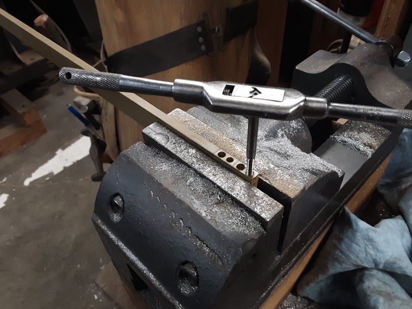
Tapping the 1st and 3rd holes, by hand. The 1st hole is 10-32 RH; the 3rd is 10-32 Left Hand.
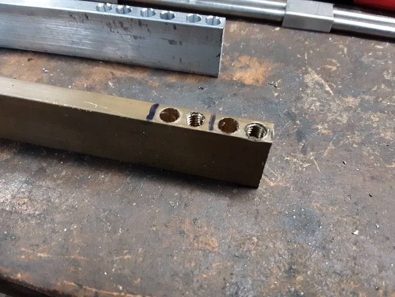
Using a Precision Sharpie to mark the cut lines between the blocks.
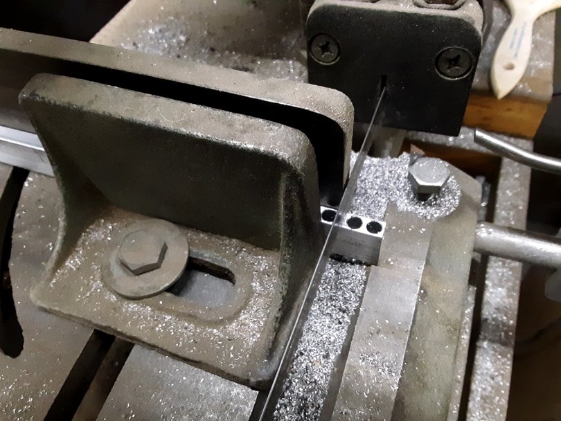
Sawing the blocks apart in my small cutoff bandsaw. Or, you can clamp the bar in the vise and saw them off with a hacksaw.
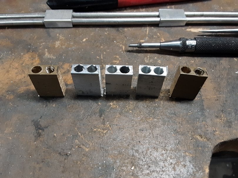
There's the set of 5 blocks, drilled, threaded and rough sawn.
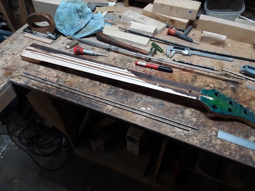
I measured and cut the 3/16" 304 stainless rod right next to the Pedulla neck. To fit this neck, the truss rod needs to be 24 3/8" overall length, from the heel to the front face of the adjusting nut. The top rod needs to be 23 1/2" long, and the bottom rod needs to be 22 3/4". The bottom rod is 3/4" shorter than the top rod.
I ground the cones on the ends and threaded both ends of the upper rod, using the process I showed in the post above. The head end is threaded 10-32 RH x 1 1/2" long. The heel end is threaded 10-32 LH x 1" long.
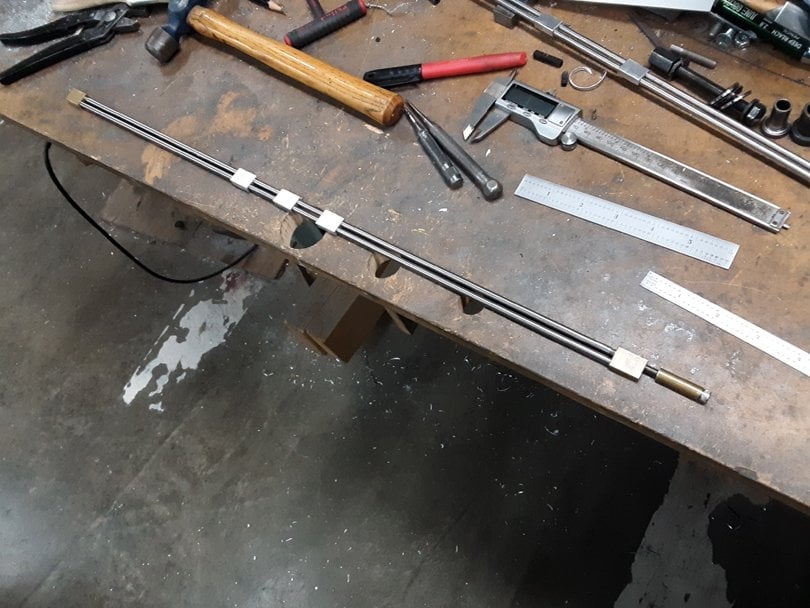
Here's the truss rod basically assembled. The procedure is to slide the top rod through the three aluminum blocks, then thread the brass blocks on both ends, leaving about 3/16" of threads on the inboard side. Then slide the bottom rod across through all the blocks.
I forgot to take pictures, but the adjusting head is a 1" long slice of 5/16" dia 360 brass bar stock. I drilled it #21 all the way through and tapped it 10-32 RH from both ends. I did it in my lathe, because it's faster, but it can be done in a drill press and a small vise. A 10-32 x 1/4" Stainless Socket Head Cap Screw is threaded into the outer end, and the whole thing is threaded 3/8" onto the end of the upper rod.
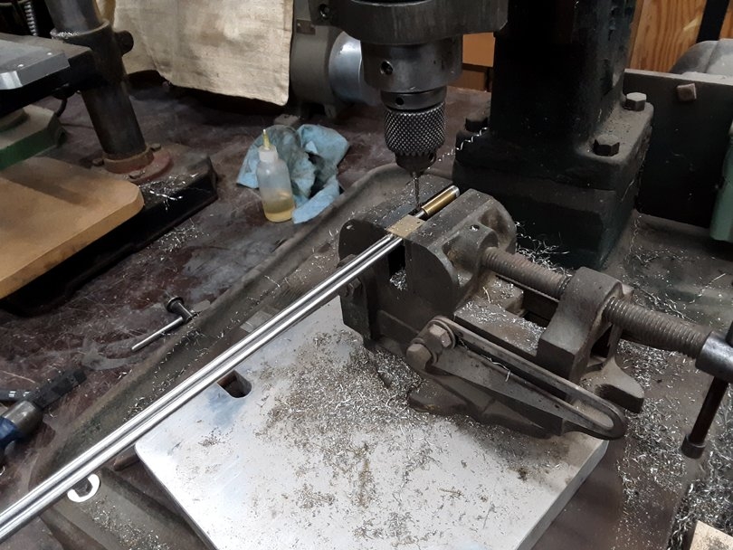
Then it gets drilled and pinned in 4 places; locking the lower rod to the two brass blocks, and locking the adjusting head parts together. I drill the holes with a 2mm bit and tap in 2mm stainless dowel pins.
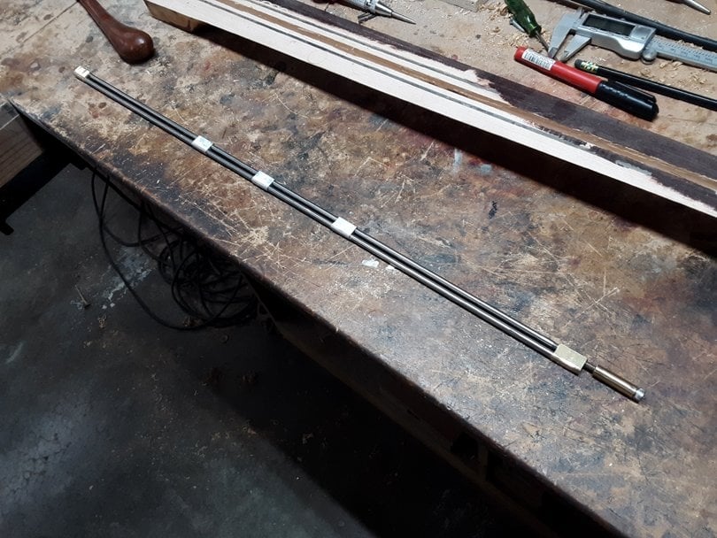
After pinning it all together, I trimmed down the top and bottom surfaces of all the blocks to about 0.010" higher than the rods. I could have done this in a vise with a big file. But I cheated and used one of my milling machines. I used the belt sander to grind off the stainless pins flush, and round off the bottoms of the blocks.
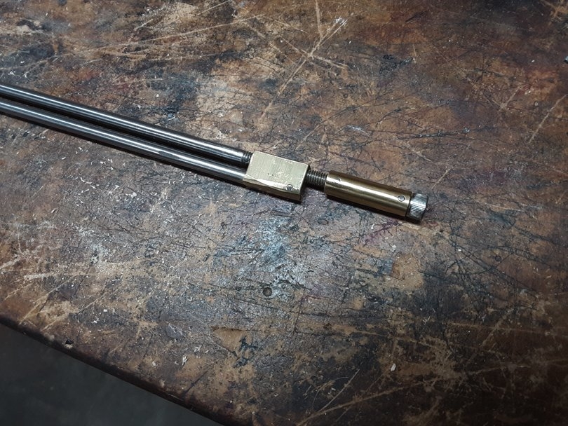
Here you can see the locations of the stainless pins. In the adjusting head, one locks the stainless cap screw to the brass barrel, and the other locks the brass barrel to the upper threaded rod.
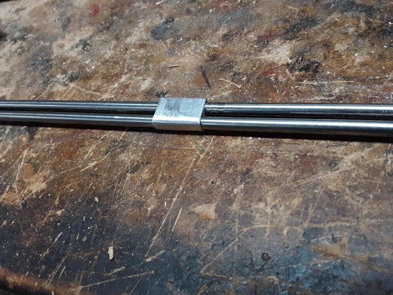
I rounded off the bottoms of all the blocks using the belt sander, to about 1/8" radius. The slot in the Pedulla neck was routed with a round bottom. I didn't want to have to rout out any more wood, because it's a pretty thin neck now.
This truss rod almost drops right into the Pedulla neck. I only have to file the trough around the adjusting nut slightly larger. This new truss rod will be much stronger than the original truss rod.
For reference, I spent about 2 hours making up this truss rod. But some of that was in messing around with the tools and process. It took a few tries to get the Left Hand threading die adjusted in to cut the threads just the right size.
If I were to make up another one right now, it would probably take about an hour. For those of you without all these cool machines, it's about a 2 hour job, and about $7 of material.
The process starts with making up the blocks. I make both the brass and aluminum blocks from 1/4" x 3/4" bar stock. The brass is 360 alloy and the aluminum is 6061 alloy. I get it online, shipped to me, from Onlinemetals.com.
I stand the bar stock up on edge and lay out the locations of the holes for the 5 blocks. If I were making up a batch of these truss rods, I might set up and drill these holes in a milling machine. But for a one-off, it's faster to do a hand layout and drill the holes in a drill press. And that's how any of you can do it, if you don't have a milling machine (yet).
On the brass bar, the 1st and 3rd holes are drilled #21, which is the tap drill size for threading 10-32. The 2nd and 4th holes, and all the holes in the aluminum bar, are drilled #12, for a sliding fit on the 3/16" rod.
In the layout, the 1st hole (from the right) is 1/8" from the end of the bar. The 2nd hole is 1/4" from the 1st. That's the center-to-center spacing of the rods. The 3rd hole is 5/16" from the 2nd. That's the space for the saw kerf to saw the blocks apart. The same spacing continues down the bar.
I did the layout with a machinist's ruler, a scriber, a small pair of dividers, and a small automatic centerpunch. And the magnifier lenses on my safety glasses. Then I center punched the spots, spot drilled them, and drilled them in the drill press, with the bar clamped in a small vise. I covered all that technique over in the Metalworking thread.
Tapping the 1st and 3rd holes, by hand. The 1st hole is 10-32 RH; the 3rd is 10-32 Left Hand.
Using a Precision Sharpie to mark the cut lines between the blocks.
Sawing the blocks apart in my small cutoff bandsaw. Or, you can clamp the bar in the vise and saw them off with a hacksaw.
There's the set of 5 blocks, drilled, threaded and rough sawn.
I measured and cut the 3/16" 304 stainless rod right next to the Pedulla neck. To fit this neck, the truss rod needs to be 24 3/8" overall length, from the heel to the front face of the adjusting nut. The top rod needs to be 23 1/2" long, and the bottom rod needs to be 22 3/4". The bottom rod is 3/4" shorter than the top rod.
I ground the cones on the ends and threaded both ends of the upper rod, using the process I showed in the post above. The head end is threaded 10-32 RH x 1 1/2" long. The heel end is threaded 10-32 LH x 1" long.
Here's the truss rod basically assembled. The procedure is to slide the top rod through the three aluminum blocks, then thread the brass blocks on both ends, leaving about 3/16" of threads on the inboard side. Then slide the bottom rod across through all the blocks.
I forgot to take pictures, but the adjusting head is a 1" long slice of 5/16" dia 360 brass bar stock. I drilled it #21 all the way through and tapped it 10-32 RH from both ends. I did it in my lathe, because it's faster, but it can be done in a drill press and a small vise. A 10-32 x 1/4" Stainless Socket Head Cap Screw is threaded into the outer end, and the whole thing is threaded 3/8" onto the end of the upper rod.
Then it gets drilled and pinned in 4 places; locking the lower rod to the two brass blocks, and locking the adjusting head parts together. I drill the holes with a 2mm bit and tap in 2mm stainless dowel pins.
After pinning it all together, I trimmed down the top and bottom surfaces of all the blocks to about 0.010" higher than the rods. I could have done this in a vise with a big file. But I cheated and used one of my milling machines. I used the belt sander to grind off the stainless pins flush, and round off the bottoms of the blocks.
Here you can see the locations of the stainless pins. In the adjusting head, one locks the stainless cap screw to the brass barrel, and the other locks the brass barrel to the upper threaded rod.
I rounded off the bottoms of all the blocks using the belt sander, to about 1/8" radius. The slot in the Pedulla neck was routed with a round bottom. I didn't want to have to rout out any more wood, because it's a pretty thin neck now.
This truss rod almost drops right into the Pedulla neck. I only have to file the trough around the adjusting nut slightly larger. This new truss rod will be much stronger than the original truss rod.
For reference, I spent about 2 hours making up this truss rod. But some of that was in messing around with the tools and process. It took a few tries to get the Left Hand threading die adjusted in to cut the threads just the right size.
If I were to make up another one right now, it would probably take about an hour. For those of you without all these cool machines, it's about a 2 hour job, and about $7 of material.
Last edited:


Here's the Secret Magic Tool for preventing Wonky threads. It's a custom-made die holder/handle.........
View attachment 7237805
That's brilliant! I wish these were commonly available.
I may have to make one of these for myself. I'm thinking something like this would be fairly easy to 3d-print. (A guide for an existing handle, that is. Not the entire handle.)
The last time i had to make a thread on a stainless steel rod I ended up filing a small step in the rod the same diameter as the minor thread diameter. (Just put the rod in a drill and file the spinning rod) This way the thinner section acted as a guide pin in the die itself. That worked very well since I only had to make two. If I had to make many a guide like this would be way easier.
I may have to make one of these for myself. I'm thinking something like this would be fairly easy to 3d-print. (A guide for an existing handle, that is. Not the entire handle.)
Sure, that would work. The guide block is just a block of something with a hole that acts as a bushing. The block can be maple or aluminum or 3D printed plastic. Design it to fit around an existing commercial die handle, attached with two machine screws or something.
So, managed to hack together a trussrod, which i'll talk about later. First, some questions about install. Bruce, you've mentioned in other posts about the truss rod channel being a quarter of an ellipse shape rather than a radius. If you're willing to share, are you using the distance from anchor to the deepest cut (5th fret) as your major radius, or maybe half the length of the entire rod? And then using the deepest part of the channel depth as minor radius?
So, managed to hack together a trussrod, which i'll talk about later. First, some questions about install. Bruce, you've mentioned in other posts about the truss rod channel being a quarter of an ellipse shape rather than a radius. If you're willing to share, are you using the distance from anchor to the deepest cut (5th fret) as your major radius, or maybe half the length of the entire rod? And then using the deepest part of the channel depth as minor radius?
Hello dazmond;
I'm glad you're following along with this! Yes, the quarter-ellipse shape of the outboard side of the curved channel has its Major Radius (horizontal) as the distance from about the nut to about the 5th fret. The Minor Radius (vertical) is from the fingerboard glue line to the lowest point of the "droop" at the 5th.
The inboard side of the curved channel is similar, but reversed and longer. Its Major Radius runs from the 5th to about the 24th.
The overall curved shape is the lower half of an ellipse, which is centered on the glue line. It's a little bit asymmetrical because the deepest point is at the 5th. That's intentional, because we want the rod to bend the outboard half of the neck more than the inboard half.
So, this took me a lot longer than it probably should have, but it's done. I have done zero machining and just a bit of woodworking before. I have been building at a friends house. There were a few do-overs and mistakes, but if I can do it, you can too! My biggest issue was with the vice wanting to shift the parts around and maybe not perfectly aligned drill press. I cheated a little with the brass sleeve. After failing at drilling a straight hole through brass stock a few times, I ended up ordering this McMaster-Carr . Cut the end off and used the existing hole to carefully make a pilot through hole, and then threading it a bit deeper.
Attachments


Now working on routing the channel. The router base is getting "hung up" on the slope.... Will the curve come out the same with some depth adjustment? Maybe my curve is suspect. router base is only 3.5" so didn't anticipate that problem.
Attachments

Now working on routing the channel. The router base is getting "hung up" on the slope.... Will the curve come out the same with some depth adjustment? Maybe my curve is suspect. router base is only 3.5" so didn't anticipate that problem.
Yes, you are right. If your router base is flat with some width, then it will rest on two points on the curved rail. And the path that the router bit follows will not exactly match the the curve of the rail.
There are two ways that you can fix this:
You can correct the shape of the curve of the rail to compensate for this. You can work it out in a full size layout. Draw a side view of the router, showing the relative positions of the bit and the two edges of the base. Then move that along the curve, with the bit following the curve. And trace the path of the two corners of the base to get the corrected curve shape.
Or, you can make a base for the router which has a gentle 2-D curve on the bottom surface, which is smaller radius than the curve on the rails. That way, the base will contact the rail at a single point, right above the router bit. The only drawback is that the router will tend to rock on the base in one axis as it gets into the flatter part of the curved rails. Not a big deal, but you just have to be more careful holding it.
On my own truss rod slot routing fixtures, I did it the first way. I used a flat base and adjusted the curve of the rails to get the final curve of the slot where I wanted it. And I lightly rounded the two edges of the router base, so they don't catch or drag on the rails.

I intend to use Bruce's DASR design going forward. I make acoustic bass guitars like this:

This one has a 28.6" scale, so I think a compression rod plus the carbon TOW will help the low E ring out as much as possible.
HOWEVER.....These are slow builds and I'm still developing the full range of models and scale lengths that I want to offer, so my time is in short supply! So if there was anyone in the European Union (I live in Italy) that would be willing to make some of these Truss rods for me, I'd be happy to pay.
Bruce, if I end up making these myself, do the following conversions into metric make sense:
Truss rod: 5mm 304 stainless steel rod with M5x0.8mm thread.
Brass barrel: I couldn't see this specified anywhere, but does 10mm diameter make sense?
Sleeve and cross bar: 10mm 6061 Aluminium (Square)
Cross pins: 2mm
Bolt: M6 (hex adjust)
Threading die: M5x0.8mm Right hand thread
Tap: M5 tap, using a 4.2mm pilot hole
This one has a 28.6" scale, so I think a compression rod plus the carbon TOW will help the low E ring out as much as possible.
HOWEVER.....These are slow builds and I'm still developing the full range of models and scale lengths that I want to offer, so my time is in short supply! So if there was anyone in the European Union (I live in Italy) that would be willing to make some of these Truss rods for me, I'd be happy to pay.
Bruce, if I end up making these myself, do the following conversions into metric make sense:
Truss rod: 5mm 304 stainless steel rod with M5x0.8mm thread.
Brass barrel: I couldn't see this specified anywhere, but does 10mm diameter make sense?
Sleeve and cross bar: 10mm 6061 Aluminium (Square)
Cross pins: 2mm
Bolt: M6 (hex adjust)
Threading die: M5x0.8mm Right hand thread
Tap: M5 tap, using a 4.2mm pilot hole
OK thanks MPU. What brass barrel diameter did you use?Those are the specs I make my versions of Bruce’s design.
I intend to use Bruce's DASR design going forward. I make acoustic bass guitars like this:
View attachment 7338108
This one has a 28.6" scale, so I think a compression rod plus the carbon TOW will help the low E ring out as much as possible.
HOWEVER.....These are slow builds and I'm still developing the full range of models and scale lengths that I want to offer, so my time is in short supply! So if there was anyone in the European Union (I live in Italy) that would be willing to make some of these Truss rods for me, I'd be happy to pay.
Bruce, if I end up making these myself, do the following conversions into metric make sense:
Truss rod: 5mm 304 stainless steel rod with M5x0.8mm thread.
Brass barrel: I couldn't see this specified anywhere, but does 10mm diameter make sense?
Sleeve and cross bar: 10mm 6061 Aluminium (Square)
Cross pins: 2mm
Bolt: M6 (hex adjust)
Threading die: M5x0.8mm Right hand thread
Tap: M5 tap, using a 4.2mm pilot hole
Yes, I've made a few of mine in metric size, and those are the specs that I used. It's very close to the American spec sizes.
You should be able to find some local metalworking shop to make these parts for you. They are easy to make. Or, maybe draw up the parts and have a batch made up by some mail-order shop. And then sell the extras!
I don't mind at all if someone gets into making and selling these truss rod kits as a side business. I'm not trying to protect the design or collect royalties.
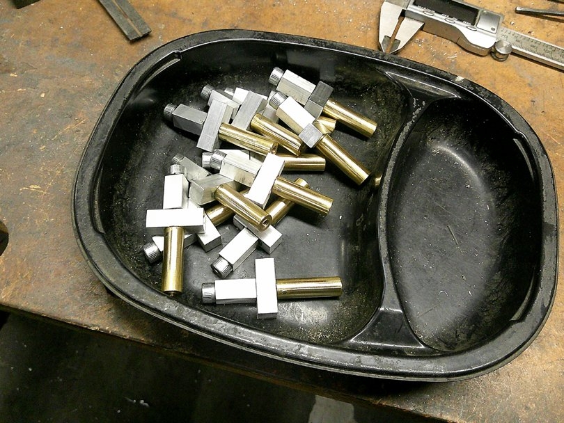
I made up another batch of my DASR adjusting heads this week, going to Bill Asher. He's been using my truss rods in all of his guitars and basses for the last several years. This batch of 12 took me just under 3 hours to make up.
Bruce, can I just triple check my understanding of the installation process before I start making dust.
For a heel adjust WITH carbon fibre TOW backstrap, the truss rod channel is routed curved from the 5th fret up to halfway between the zero and 1st fret. From the 5th fret to the heel the channel is flat, running parallel with the fretboard, and at the depth of the droop. The TOW is then placed in the channel from the heel up to the 5th fret. The truss rod is clamped at the 5th, and the two anchors (the slug at the headstock, and the crossbar at the heel) which are level with the fretboard, force the truss rod into the eliptical shape. When gluing, epoxy fills the channel under the rod between the heel and the 5th fret. A maple filet pushes the truss down for gluing.
For a heel adjust WITHOUT carbon fibre TOW, then the channel is routed eliptically in BOTH directions from the 5th fret.
EDIT to add in one more question...
You seem to use a 2 degree angle at both the slug and the anchor. Obviously the curve has a different radius, so does that mean that the angle is not that sensitive? ie 2 degrees is fine for both ends of the rod, and also for different scale lengths? Or do I really need to be drilling the angle accurately depending on the exact radius of each installation?
For a heel adjust WITH carbon fibre TOW backstrap, the truss rod channel is routed curved from the 5th fret up to halfway between the zero and 1st fret. From the 5th fret to the heel the channel is flat, running parallel with the fretboard, and at the depth of the droop. The TOW is then placed in the channel from the heel up to the 5th fret. The truss rod is clamped at the 5th, and the two anchors (the slug at the headstock, and the crossbar at the heel) which are level with the fretboard, force the truss rod into the eliptical shape. When gluing, epoxy fills the channel under the rod between the heel and the 5th fret. A maple filet pushes the truss down for gluing.
For a heel adjust WITHOUT carbon fibre TOW, then the channel is routed eliptically in BOTH directions from the 5th fret.
EDIT to add in one more question...
You seem to use a 2 degree angle at both the slug and the anchor. Obviously the curve has a different radius, so does that mean that the angle is not that sensitive? ie 2 degrees is fine for both ends of the rod, and also for different scale lengths? Or do I really need to be drilling the angle accurately depending on the exact radius of each installation?
Last edited:
For head adjust you route just like for heel adjust, just the adjusting end needs routing at head, not at heel. Everything else is similar. Maple wedge and cf tow from heel to 5-6th fret under the truss rod on both.
Latest posts
-

-

-
-
 TC Electronic Spark Booster. Underrated champion of low-gain overdrives
- Latest: John D Harris
-
