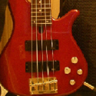
I was inspired by the EQ discussion thread to run several basic class D simulations in SPICE to illustrate how it works.
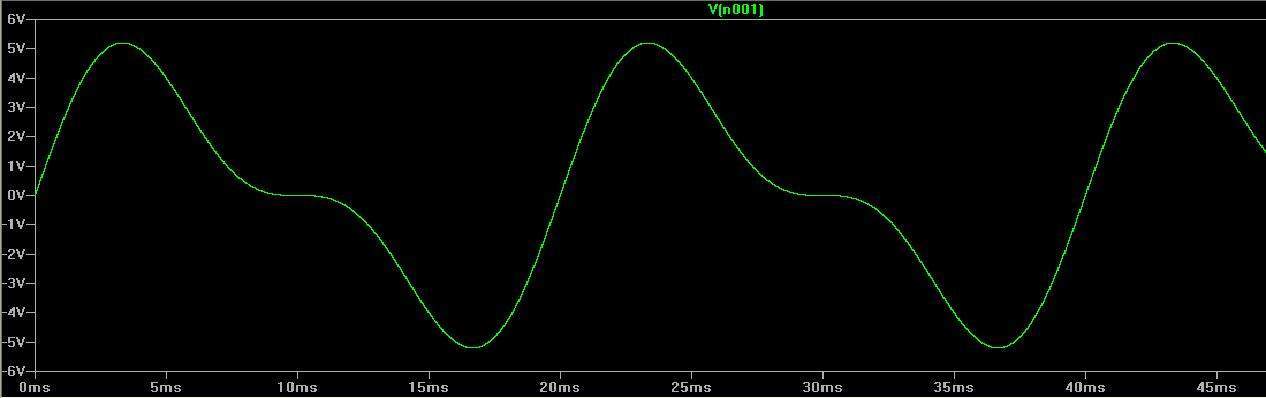
Let's say you were playing a low G and you ran your bass into a preamp...if you looked at the signal for a brief slice of time, it'd probably look a lot like this:
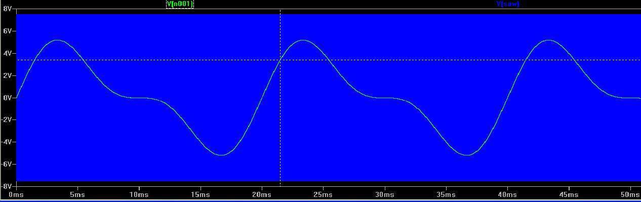
First, the class D amp will sample the audio. Sampling is done by comparing the audio to a triangle or sawtooth wave that is much higher in frequency. In this case, the sampling frequency is 400KHz, which is close to the frequency range of AM radio broadcasts in the USA. 400KHz has almost become an industry standard...more on that later. Anyway, in the next pic I'm going to overlay this audio wave on top of the saw. In comparison, the saw will just look like a blue bar. Notice that I've dropped a marker at a point on the audio wave:
This picture was just for reference. Now, I'm going to zoom in...

Now that we are zoomed in, the audio looks like a straight line and you can see the sawtooth wave. Each sawtooth is equivalent to a sampling period. As I mentioned above, the audio is compared to the sawtooth. This is accomplished with an electronic device called...a comparator. This changes our audio wave into a stream of pulses. Now, I'm going to add in the pulses to show how they line up:
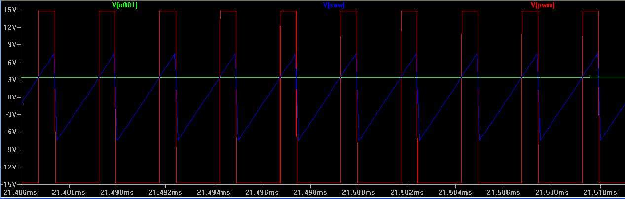
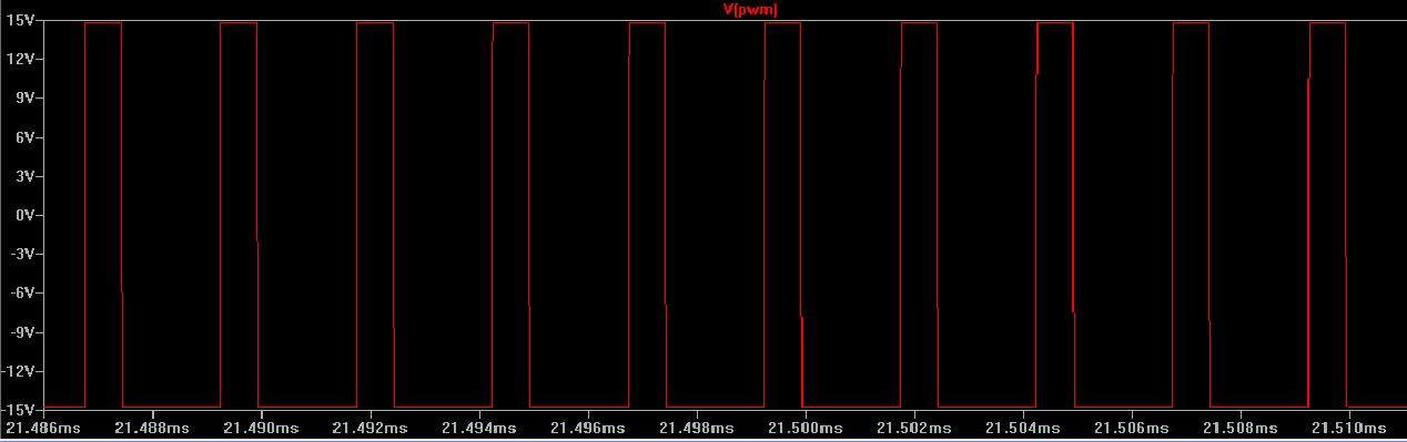
Notice the pulse transitions occur where the audio wave intersects the sawtooth wave. Each pulse represents a sample. Just to make it less confusing (hopefully), here is what the pulses look like by themselves:
So what happens when there is no input? In the next pic, I turned the volume knob all the way down so to speak and plotted zero input on top of the saw:
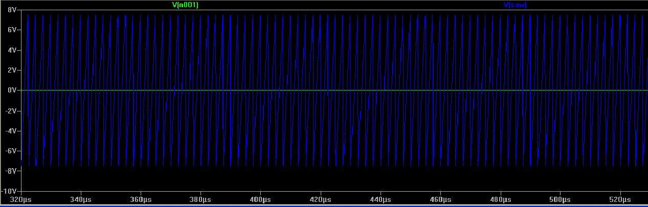
Now, I'm going to zoom in and plot the resulting pulses that come out of the comparator. Notice that our input of zero is intersecting the saw right in the middle, which makes the pulses have equal width at the top and bottom. Think about the top part of the pulses as ON, and the bottom part as OFF. Since the length of ON time is equal to the length of OFF time, we have essentially encoded zero.

So what happens if I inject a + voltage instead of audio? Here you go:

Notice that the pulses are extremely narrow at the top because of where the input voltage intersects the saw. Now, I'm going to inject a - voltage...

Now the pulses are extremely wide at the top because of where in the input voltage intersects the saw.
Hopefully it will be clear that unlike a DC voltage which is fixed, and audio waveform is changing constantly, so in the case of class D where we compare the audio with a sawtooth wave, the width of the pulses will be changing constantly. This is called pulse width modulation, or PWM for short.
So now what? The pulses are amplified because we need enough voltage and current to drive a speaker. Usually the pulses are amplified with MOSFET devices because they are relatively easy to turn on and off quickly, which is important, because in this case, they would be turning on and off 400,000 times a second. Class D amp efficiency stems from the amplification of a signal that is essentially either on or off. Heating in older amplifier designs comes from transistors essentially operating as variable resistors. The transistors in class D amps are essentially operating as switches.
After the PWM is amplified, it is connected to the speaker output through a passive low pass filter. This filter is very much like a low pass filter found in a speaker cabinet crossover. Here is what the output audio looks like:
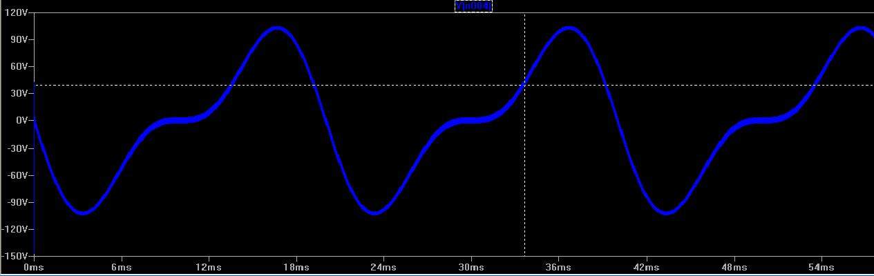
The tech savy here will notice that this would be a pretty darn powerful amp. We have somewhere around +/-100 volts of signal swing and we started with +/- 5 volts. If you compare this pic with the first, you will notice that it's upside down...more on that later.
I've hit the picture limit with this first post, and I will pick it back up later...
Let's say you were playing a low G and you ran your bass into a preamp...if you looked at the signal for a brief slice of time, it'd probably look a lot like this:
First, the class D amp will sample the audio. Sampling is done by comparing the audio to a triangle or sawtooth wave that is much higher in frequency. In this case, the sampling frequency is 400KHz, which is close to the frequency range of AM radio broadcasts in the USA. 400KHz has almost become an industry standard...more on that later. Anyway, in the next pic I'm going to overlay this audio wave on top of the saw. In comparison, the saw will just look like a blue bar. Notice that I've dropped a marker at a point on the audio wave:
This picture was just for reference. Now, I'm going to zoom in...
Now that we are zoomed in, the audio looks like a straight line and you can see the sawtooth wave. Each sawtooth is equivalent to a sampling period. As I mentioned above, the audio is compared to the sawtooth. This is accomplished with an electronic device called...a comparator. This changes our audio wave into a stream of pulses. Now, I'm going to add in the pulses to show how they line up:
Notice the pulse transitions occur where the audio wave intersects the sawtooth wave. Each pulse represents a sample. Just to make it less confusing (hopefully), here is what the pulses look like by themselves:
So what happens when there is no input? In the next pic, I turned the volume knob all the way down so to speak and plotted zero input on top of the saw:
Now, I'm going to zoom in and plot the resulting pulses that come out of the comparator. Notice that our input of zero is intersecting the saw right in the middle, which makes the pulses have equal width at the top and bottom. Think about the top part of the pulses as ON, and the bottom part as OFF. Since the length of ON time is equal to the length of OFF time, we have essentially encoded zero.
So what happens if I inject a + voltage instead of audio? Here you go:
Notice that the pulses are extremely narrow at the top because of where the input voltage intersects the saw. Now, I'm going to inject a - voltage...
Now the pulses are extremely wide at the top because of where in the input voltage intersects the saw.
Hopefully it will be clear that unlike a DC voltage which is fixed, and audio waveform is changing constantly, so in the case of class D where we compare the audio with a sawtooth wave, the width of the pulses will be changing constantly. This is called pulse width modulation, or PWM for short.
So now what? The pulses are amplified because we need enough voltage and current to drive a speaker. Usually the pulses are amplified with MOSFET devices because they are relatively easy to turn on and off quickly, which is important, because in this case, they would be turning on and off 400,000 times a second. Class D amp efficiency stems from the amplification of a signal that is essentially either on or off. Heating in older amplifier designs comes from transistors essentially operating as variable resistors. The transistors in class D amps are essentially operating as switches.
After the PWM is amplified, it is connected to the speaker output through a passive low pass filter. This filter is very much like a low pass filter found in a speaker cabinet crossover. Here is what the output audio looks like:
The tech savy here will notice that this would be a pretty darn powerful amp. We have somewhere around +/-100 volts of signal swing and we started with +/- 5 volts. If you compare this pic with the first, you will notice that it's upside down...more on that later.
I've hit the picture limit with this first post, and I will pick it back up later...





 but despite that, I'm sure plenty of folks will understand it and be much appreciative.