• TalkBass has been independent since 1998. Add your voice.
    Create a free account to reply to discussions, view embedded media, and browse with fewer display ads.
    Join freeLog in
    Want zero display ads or expanded classifieds tools? Compare plans.

Double P bass pickup wiring question.

Hi.
I got a lot of information from here, but it's the first time I joined and wrote. :)

I would like to ask you about double-P pickup wiring.

There is a model called Fender Japan PB-555.
fender pb-555 - Google Search
Like this model, I want to mount both pickups close together.

The reason I want to put it as close as possible is because I want to put in a mode to mix the two pickups.
The 'Mix' does not means parallel of two pickups. I want to use the D,G sides of the neck pickup and the E,A sides of the bridge pickup.(serial)
May be the result is the same as that of a reverse-type P pickup located between the neck pickup and the bridge pickup.

As a result, I want to implement the following four modes through the rotary switch.
1. Neck Pickup / 2. Bridge Pickup / 3. Neck + Bridge Parallel / 4. Neck D, G Side + Bridge E, A Side Serial

pp_wiring_4mod.jpg


The thing that I most worry about is wiring
The PB-555 model has the above mentioned modes, but if you listen to the sound samples, you can hear the smaller output with thinner sound.


I wonder if out-of-phase is happening.

Please let me know how to do the wiring 'mode 4' without out of phase,.
Of course, I assume that use the same brand same pickup.
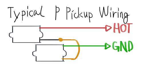
Below is an example color code. Please explain to me based on this color code.

pp wiring.jpg
 
  • Like
Reactions: PawleeP
pp wiring.jpg

1, 2, and 3 are the three positions of a DP3T switch. I think this should do what you want. The common hot line goes to the volume pot and the common ground goes to the back of the volume pot (which presumably is connected to the ground lug of the output jack).

We're taking advantage here of the fact that current has to have somewhere to go; if a component is disconnected at one end, it's effectively out of the circuit. In position 1, the lower pickup isn't connected at all, so it's inactive. In position 2, the hot lead of the upper pickup and the ground lead of the lower pickup aren't connected, so current flows from the hot lead of the lower pickup, through the middle gold wire that I added, and out through the ground lead of the upper pickup. In position 3, the upper pickup isn't connected. Thus you get the behavior you want: position 1 is the upper pickup, position 2 is the D/G of the upper pickup and E/A of the lower pickup, and position 3 is the lower pickup.
 
View attachment 3220568
1, 2, and 3 are the three positions of a DP3T switch. I think this should do what you want. The common hot line goes to the volume pot and the common ground goes to the back of the volume pot (which presumably is connected to the ground lug of the output jack).

We're taking advantage here of the fact that current has to have somewhere to go; if a component is disconnected at one end, it's effectively out of the circuit. In position 1, the lower pickup isn't connected at all, so it's inactive. In position 2, the hot lead of the upper pickup and the ground lead of the lower pickup aren't connected, so current flows from the hot lead of the lower pickup, through the middle gold wire that I added, and out through the ground lead of the upper pickup. In position 3, the upper pickup isn't connected. Thus you get the behavior you want: position 1 is the upper pickup, position 2 is the D/G of the upper pickup and E/A of the lower pickup, and position 3 is the lower pickup.


Thanks for the detailed and clear answer!

I would like to ask additional questions.

Three of the modes I would like to implement are likely to be implemented by your description (modes 1, 2, and 4).
However, I am wondering what to do with the typical two-pickup parallel mode configuration, which corresponds to mode 3.

I have drawn a diagram.

pp wiring parallel.jpg


I want to configure it as a 4T rotary switch.
Which of these should be done? Should I do it with no.2? Or does it work on both?
But I do not have a certain in no.1, so I think I will do with no.2 method in the end ... Anyway, I want to hear your answer.
 
Oh, sorry, I completely forgot about both pickups in parallel. Hmm. This makes it more complicated. If you try to add the "both in parallel" option to my diagram (call it #4), you need a way to disable the middle gold wire that I added. That wire is only needed for #2, but to make it optional you need either a separate switch for it or you need one more pole on your rotary switch. Then you'll need yet another pole for the parallel option. So now you've got a 4P4T rotary switch, which is a fairly large object. I put a 3P4T rotary switch into my Fender Jazz for a custom wiring scheme I designed, and I had to use a dremel to widen the control cavity a little. Maybe you can find a smaller one than the one I used.

It's getting late for me, so I'm not going to draw the picture, but basically you can modify my drawing above. Cut the middle gold wire that I added into two pieces; connect them to poles 3 and 4 of position #2 on the switch, then add a jumper between poles 3 and 4 on the common output lugs (NOT on position #2). That makes that connection active only in position #2 and sets us up for the parallel option too.

For the "both in parallel" option, you need the red and green connections in your latest drawing, but they have to be active only in position #4. I think if the hot lead from the upper pickup goes to position #4 pole 1, upper pickup ground to pole 2, lower pickup hot to pole 3, and lower pickup ground to pole 4, then along with the jumper you added above, the two pickups will be in parallel in position #4 but not in the other positions.

Why don't you draw that out and post it and I'll take a look at it tomorrow. If you want the parallel option to be position 3, just swap positions 3 and 4 in my drawing and description.
 
Oh, sorry, I completely forgot about both pickups in parallel. Hmm. This makes it more complicated. If you try to add the "both in parallel" option to my diagram (call it #4), you need a way to disable the middle gold wire that I added. That wire is only needed for #2, but to make it optional you need either a separate switch for it or you need one more pole on your rotary switch. Then you'll need yet another pole for the parallel option. So now you've got a 4P4T rotary switch, which is a fairly large object. I put a 3P4T rotary switch into my Fender Jazz for a custom wiring scheme I designed, and I had to use a dremel to widen the control cavity a little. Maybe you can find a smaller one than the one I used.

It's getting late for me, so I'm not going to draw the picture, but basically you can modify my drawing above. Cut the middle gold wire that I added into two pieces; connect them to poles 3 and 4 of position #2 on the switch, then add a jumper between poles 3 and 4 on the common output lugs (NOT on position #2). That makes that connection active only in position #2 and sets us up for the parallel option too.

For the "both in parallel" option, you need the red and green connections in your latest drawing, but they have to be active only in position #4. I think if the hot lead from the upper pickup goes to position #4 pole 1, upper pickup ground to pole 2, lower pickup hot to pole 3, and lower pickup ground to pole 4, then along with the jumper you added above, the two pickups will be in parallel in position #4 but not in the other positions.

Why don't you draw that out and post it and I'll take a look at it tomorrow. If you want the parallel option to be position 3, just swap positions 3 and 4 in my drawing and description.


If the switch is 4P4T rotary, I can draw the diagram like this.

pp wiring rotary_4p4t.jpg


However, it is difficult to obtain a suitable size 4P4T switch.
3P4T is much easier to find the right one, so I would like to solve it with 3P4T. But I given up to draw the diagram using 3P4T.

Can you configure the above 4 modes with 3P4T?
 
I've had pretty good luck with 4P6T rotary switches that I've bought off eBay -- you could maybe get one of those (they seem reasonably easy to find) and then come up with a couple other settings you might like to set up on the other two positions. For example you could do the *outer* two pickup halves together, and maybe throw the two of them together in series or something.

Looking now it doesn't seem like the ones I was buying a few years ago are readily available anymore, but this looks reasonably close (can't tell how big it is though): [Invalid or Expired Link Removed]

Aside from that, the Free-Way switch (4p6t) or Super Strat switch (that's 4p5t) that @spaceatl suggests will definitely work. I'm pretty sure that you need the 4-pole switch to make all the combinations possible that you want (but don't quote me on that, if someone comes up with a cool wiring scheme then I will happily stand corrected).
 
Maybe checkout the Freeway switch?

Invalid Link Removed

or perhaps a strat super switch?


[Invalid or Expired Link Removed]
I looked at the schematic and it seems impossible to do the configuration I want because of double pole.
Please let me know if I am misunderstanding about it.

Strat Super Switch need slot route but there's no slot route.
 
I've had pretty good luck with 4P6T rotary switches that I've bought off eBay -- you could maybe get one of those (they seem reasonably easy to find) and then come up with a couple other settings you might like to set up on the other two positions. For example you could do the *outer* two pickup halves together, and maybe throw the two of them together in series or something.

Looking now it doesn't seem like the ones I was buying a few years ago are readily available anymore, but this looks reasonably close (can't tell how big it is though): [Invalid or Expired Link Removed]

Aside from that, the Free-Way switch (4p6t) or Super Strat switch (that's 4p5t) that @spaceatl suggests will definitely work. I'm pretty sure that you need the 4-pole switch to make all the combinations possible that you want (but don't quote me on that, if someone comes up with a cool wiring scheme then I will happily stand corrected).


Thank you for good recommendations.
I think it is good to have more modes. (Especially the two pickups seires mode)

But I did not fail to get 4P4T(or4P6T) either. It just does not get enough compact size products.

It sounds a little bit crazy, but the bass that is going to apply this plan is the Epiphone Jack Cassidy.
Therefore, there is no control cavity, and I have to put it through F-hole or pick-up route.

So I would like to use a product similar with the original switch, but I can't get it.

The product you are recommending might be well enough, but I can not guarantee it.

4P4T 4 Pole 4 Position 2 Deck Band Channel Rotary Switch Selector with Knob 714998403735 | eBay: JMgAAOSwNDhbzXOI: rk: 1: pf: 0
I have found these products but I am not sure if this is going to be okay.

2 x Alpha 10mm Rotary Switch 4 Pole 4 Throw 4P4T 20mm Knurled Shaft | eBay: rk: 3: pf: 0
Or there is such a product, but it is concerned that the shaft length is short. The thickness of the the hollow body bass top is thicker than expected.

You gave me additional thing to worry about. After hearing your suggestions, I suddenly wanted to add a series mode too. Haha, I am very confusing....
 
Last edited:
As an eBay Associate, TalkBass may earn a commission from qualifying purchases.
Ah my bad, I thought the Free-Way was a 4p6t, but there aren't enough connections for it to be that. Yeah getting a switch with the appropriate shaft length might be a problem -- that said, I'd expect that the Free-Way Switch would *fit* at least, given that it's probably mostly intended for use in Les Pauls and 335s. Not sure how to wire a scheme such as yours with that switch though.
 
I done it! Decided it!
I decided to solve it this way.

pp wiring rotary pushpull.jpg


Inspired by what solderfumes said, I decided to add two pickup series modes as well.
I listened to some of the sound samples of some double P-bases, such as the Mockingbird bass, and thought it was a mode with awesome growling.

So I decided to construct with 3P4T rotary switch and push-pull pot as above.
The operation may be a little inconvenient, but unlike guitar, it is wouldn't be matter since there is very little chance to operate the selector during performance.

The rotary switch can select four modes: neck / neck+bridge parallel / bridge / neck+bridge series,
and can use bridge E,A+neck D,G mode by pulling the push-pull pot with rotary switch sets to neck+bridge series.
NeckE,A and Bridges D,G were omitted because they would not be used. So in fact, the number of all cases can be applied!

I wanted to use Bridge E, A and Neck D and G modes because I am missing the sound of Aria Pro 2 CSB-450 model.
csb-450 - Google Search
It's a 32 inch scale set-in neck bass with P-bass styled sound.
But the pick-up position was located slightly backward and the polepiece was also a reverse type, so it has a tight modern sound than the typical P-bass.
But It has just one pick-up, so I've sold it for use different basses, but the sound of it was fit for my taste very well.

I expect the bridge E,A and Neck D,G mode make the sound of CSB-450.

Anyway, thanks for all the advice!
 
I done it! Decided it!
I decided to solve it this way.

View attachment 3223866

Inspired by what solderfumes said, I decided to add two pickup series modes as well.
I listened to some of the sound samples of some double P-bases, such as the Mockingbird bass, and thought it was a mode with awesome growling.

So I decided to construct with 3P4T rotary switch and push-pull pot as above.
The operation may be a little inconvenient, but unlike guitar, it is wouldn't be matter since there is very little chance to operate the selector during performance.

The rotary switch can select four modes: neck / neck+bridge parallel / bridge / neck+bridge series,
and can use bridge E,A+neck D,G mode by pulling the push-pull pot with rotary switch sets to neck+bridge series.
NeckE,A and Bridges D,G were omitted because they would not be used. So in fact, the number of all cases can be applied!

I wanted to use Bridge E, A and Neck D and G modes because I am missing the sound of Aria Pro 2 CSB-450 model.
csb-450 - Google Search
It's a 32 inch scale set-in neck bass with P-bass styled sound.
But the pick-up position was located slightly backward and the polepiece was also a reverse type, so it has a tight modern sound than the typical P-bass.
But It has just one pick-up, so I've sold it for use different basses, but the sound of it was fit for my taste very well.

I expect the bridge E,A and Neck D,G mode make the sound of CSB-450.

Anyway, thanks for all the advice!
wow, thats alot of bells and whistles!
and i thought i was over complicating some of my pj's by adding a 3 way pup selector and/or a ser-par sw to the p pup.. geeze!
thanx for the diagram though.. just in case i ever want to drive myself completely insane.. lmao, p
 
It sounds a little bit crazy, but the bass that is going to apply this plan is the Epiphone Jack Cassidy.
Therefore, there is no control cavity, and I have to put it through F-hole or pick-up route.

I am curious. Have you routed the Casady for the pickups yet? If so, could you please post a photo? Thanks.

P.S. It does strike me as a little bit crazy, but I'd like to see the results.
 
I am curious. Have you routed the Casady for the pickups yet? If so, could you please post a photo? Thanks.

P.S. It does strike me as a little bit crazy, but I'd like to see the results.


I have a plan. But I have not started working yet. I will use expedient because I do not have professional equipment and skills. I wish there will be a good results.

I will inform you as soon as the work progresses. But I am busy and I do not know when to try.
Maybe I expect the results to be posted to a separate thread.

In fact, it is the first time I use hollow body bass and I do not particularly like it. It is just a cheap sale and a curious purchase. However, the sound quality is way good than I expected and it is surprisingly well suited to various genre rocks (I use it as a p-bass feeling). I think the sound of Jack Cassidy is already very rocking, but I thought it would be better to have a straight, rocking sound if I had a pickup on the bridge side.
 
Last edited: