• TalkBass has been independent since 1998. Add your voice.
    Create a free account to reply to discussions, view embedded media, and browse with fewer display ads.
    Join freeLog in
    Want zero display ads or expanded classifieds tools? Compare plans.

Ernie Ball Stringray 5 causing confusion on my work bench! Help!

Hello,

Long time lurker first time posting,

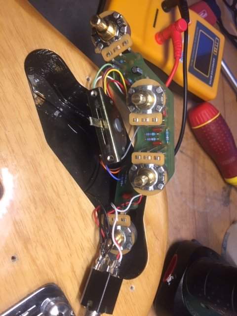
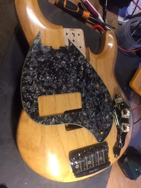
I have what I think is a 2000 Stingray 5 on my workbench, its not outputting any signal, but does make a thwacking noise as it should when you put a small screwdriver on the pickups magnet poles, which is confusing, I have been over most things.

Checked the battery circuit is good and voltage is getting to the board and IC
Earth continuity tests

output jack is soldered correctly

Pots seem ok although the middle two don't measure 50K on meter, maybe because they're in circuit?

I normally repair guitars not basses so excuse my ignorance.

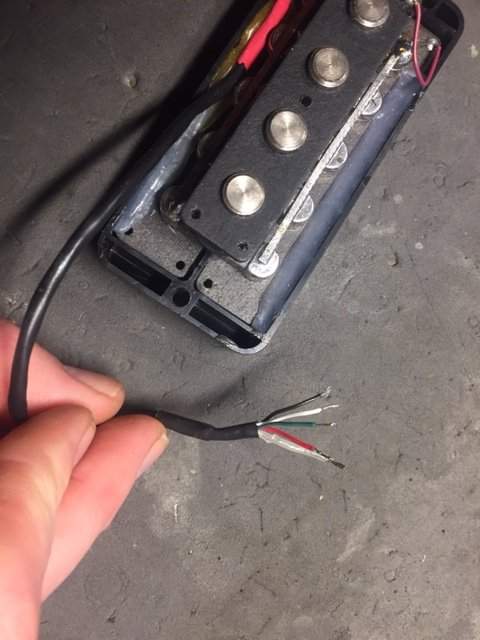
I want to test the pickup on its own without the circuit, the colours are red, green, black white and an earth, could someone tell me which cables to solder together to test the pickup on a mono output jack to an amp and see if it is working properly, or what meter readings should be from which combination of wires?
IMG_8403.JPG


IMG_8402.JPG


IMG_8401.JPG


IMG_8400.JPG


Any help or advice would be greatly appreciated, I am slightly baffled that tapping the pickup magnet makes a noise but playing the instrument strung up makes no noise, but its been a long day and I am willing to be told im an idiot!

I don't know how to test the IC chip is healthy, but one of the pins is getting 8.4V from the battery.
 
Last edited:
...I want to test the pickup on its own without the circuit, the colours are red, green, black white and an earth, could someone tell me which cables to solder together to test the pickup on a mono output jack to an amp and see if it is working properly, or what meter readings should be from which combination of wires?
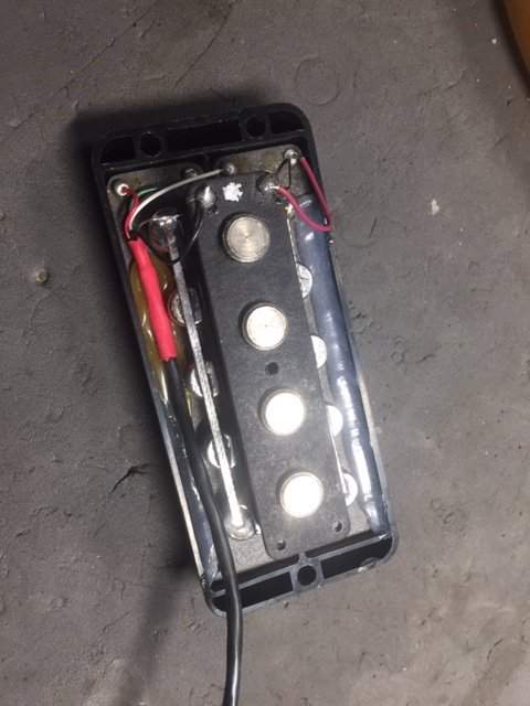
Instead of testing the whole pickup, by soldering together some wires, I recommend you to test each pickup half individually. As you can see there are 2 coils under the strings and a phontom coil (to cancel the hum on) under the pickup.
So, if we look at this photo (from Help me understand dummy coils in MM style pickups.):

post-12-1216738980-jpg.2227511


To test the neck coil alone: connect the red and green to your mono output.
To test the bridge coil alone: connect the white and bare wire (ground) to your mono output.
To test the bridge coil together with phantom coil: connect the white and black to your mono output.

ps: If you want to search for more info, you can search Sterling electronics, too. Because Stingray5 electronics are basically like Sterling H.
 
Hi , thanks for your reply, I finally solved the issue, there was a tech before me who was given this job before he left town, he had replaced the output jack, but maybe with the wrong one, I noticed that there was voltage on the board without a cable plugged in to the jack, so I plugged the cable in and the voltage disappeared from the board which is back to front.
So I joined both the red from the battery and the red from the board together leaving the black on sleeve and white on tip of the stereo jack and suddenly the whole bass worked.
I then tried putting the two red cables in various configurations on the jack but nothing worked. do MM use a very specific stereo jack for these basses?
I spent hours chasing different things before I got to this very basic discovery!!! , I did make a testing kit with alligator clips and a jack to test pickups out of circuit.

I resoldered lots of dodgy looking solder, all sorts of stuff so I guess it was a good learning curve, detective work, process of elimination!

So either I haven't worked out the jack wiring or the previous tech put in something that can't work?!
 
Red from battery always goes to the preamp board, never to the jack. Put the black from the battery on the output jack ring. All other grounds terminate at the output jack sleeve. That way the circuit is completed by the cable plug when it is inserted, by the sleeve of the plug connecting the ring and sleeve of the jack together, thus completing the ground to the battery and turning on the preamp.

Output from the preamp (the white wire) goes to the tip of the stereo jack as before.

Active bass wiring 101... You won't find stuff like this in your typical passive Strat or Les Paul, but it is very common in electric basses with preamps.
 
No special output jack used on the Stingrays, just standard TRS jacks.

From your discovery of “voltage at the board with no cable plugged in”, sounds like the output Jack was mis-wired. Did you have a wiring diagram to go by?

Sounds like you’ve solved the issue.
 
...do MM use a very specific stereo jack for these basses?
Yes, Musicman basses use a specific output jacks.

No special output jack used on the Stingrays, just standard TRS jacks.

Red from battery always goes to the preamp board, never to the jack.
...
Active bass wiring 101...
Please see the post I linked on post #3 here. This schematic is from that post:

sr5-20wiring-jpg.2227512
 
My bad - the schematic shows 4 contact points on the output jack, not 3. I have never had one of these open before, so it appears that they are using a TS jack with a switching mechanism in it to connect the battery + to the preamp board when a cable is plugged into the jack, not using the sleeve of the cable plug to complete the ground. If a std TRS is substituted for this, it could/would result in the bass appearing to have no output, and could/would short the battery to ground, with potential safety issues if the battery overheats due to the short.

The exact OEM fix would be to use the proper replacement jack. EBMM should be able to provide the part, or at least get you the model number for the (I believe) Switchcraft jack. However, IMHO the bass could be re-wired as in my previous post (#5) with a regular TRS jack as per the majority of the active basses on the planet, and it should work fine. The only real change would be switching battery - instead of switching battery + to get the preamp to power up.

Just my $.02 USD. Like the credits at the end of Brooklyn 99 say, "Not a Doctor"...
 
Thanks for all your help guys,
Luckily for me the outgoing tech on this job had left the original MM jack in the case, it was not working only due to corrosion and oxidisation , so I cleaned that sucker, soldered it back in and the bass works as it should!

I brushed up my skills on this one, on an 8 hour arc back to the beginning!!!
 
  • Like
Reactions: Inara
It appears that they may be using this type of jack, a Switchcraft 113 or 113X:

[Invalid or Expired Link Removed]
yep, and it's ridiculous

a common mod is to replace it with a standard (and much more robust) #12B TRS jack, but do it right :)

that means red from preamp goes straight to red from 9V and nowhere else, black from 9V gets separated out from all the other grounds and sent to ring, then all other grounds go to sleeve.

the only purpose i can see for music man's overly complicated +9V-interrupting jack is that after the mod to a more "normal" active setup you can get a momentary noise when you plug in from the pre powering up. thing is we all know to have the sound muted when we first plug in anyway, right?
 
  • Like
Reactions: Geri O
yep, and it's ridiculous

a common mod is to replace it with a standard (and much more robust) #12B TRS jack, but do it right :)

that means red from preamp goes straight to red from 9V and nowhere else, black from 9V gets separated out from all the other grounds and sent to ring, then all other grounds go to sleeve.

the only purpose i can see for music man's overly complicated +9V-interrupting jack is that after the mod to a more "normal" active setup you can get a momentary noise when you plug in from the pre powering up. thing is we all know to have the sound muted when we first plug in anyway, right?

Been waiting for this comment to arrive. Walter for the win!

I performed this mod on one of my past Stingrays when I got concerned about the low gripping power of the 1/4" jack. I saw Walter's post on this and I was able to use a Switchcraft output jack I had on hand (the one Walter listed above - we kept those on hand at the audio shop for various rack projects before the digital desks surfaced. Still have a couple of dozen of them in a desk drawer somewhere near by). Rewired the new output jack per Walter's instructions and bouyah, I was up and running again. And left wondering why the OEM switch was deemed a good idea in the first place.
 
  • Like
Reactions: walterw
Instead of testing the whole pickup, by soldering together some wires, I recommend you to test each pickup half individually. As you can see there are 2 coils under the strings and a phontom coil (to cancel the hum on) under the pickup.
So, if we look at this photo (from Help me understand dummy coils in MM style pickups.):

post-12-1216738980-jpg.jpg


To test the neck coil alone: connect the red and green to your mono output.
To test the bridge coil alone: connect the white and bare wire (ground) to your mono output.
To test the bridge coil together with phantom coil: connect the white and black to your mono output.

ps: If you want to search for more info, you can search Sterling electronics, too. Because Stingray5 electronics are basically like Sterling H.

If the green and bare wire were connected to ground and the red and white were connected to hot, would that place the bridge and neck coil in parallel together, while also excluding the phantom coil? Would that produce a "setting" similar to what the 3-way switch offers?