• TalkBass has been independent since 1998. Add your voice.
    Create a free account to reply to discussions, view embedded media, and browse with fewer display ads.
    Join freeLog in
    Want zero display ads or expanded classifieds tools? Compare plans.

fEarful 12/6 build by blakelock

Howdy folks,
Figured I’d tell my fEarful 12/6 build story for all the noobs (like me) out there. I chose to go with the simplest system. No tweeter and, although I was tempted by some of the other mid drivers (faital, 6ND410, etc.), I chose the alphalite 6A mid driver since it has the simplest crossover (here).

Main items I bought:
a cut kit from swift
3012LF speaker from speakerhardware.com (~$30 cheaper than most other places)
alphalite from partsexpress
crossover components from erseaudio.com (note: some items were listed as out of stock but still shipped to me immediately)


Initial box assembly

I printed out a few choice thread entries and diagrams from the fEarful wiki to get an idea about assembly order. Dry fitting the kit (clamping together without glue) was very necessary. It helped me understand how the kit fit together. It’ll also show if a little trimming is needed.

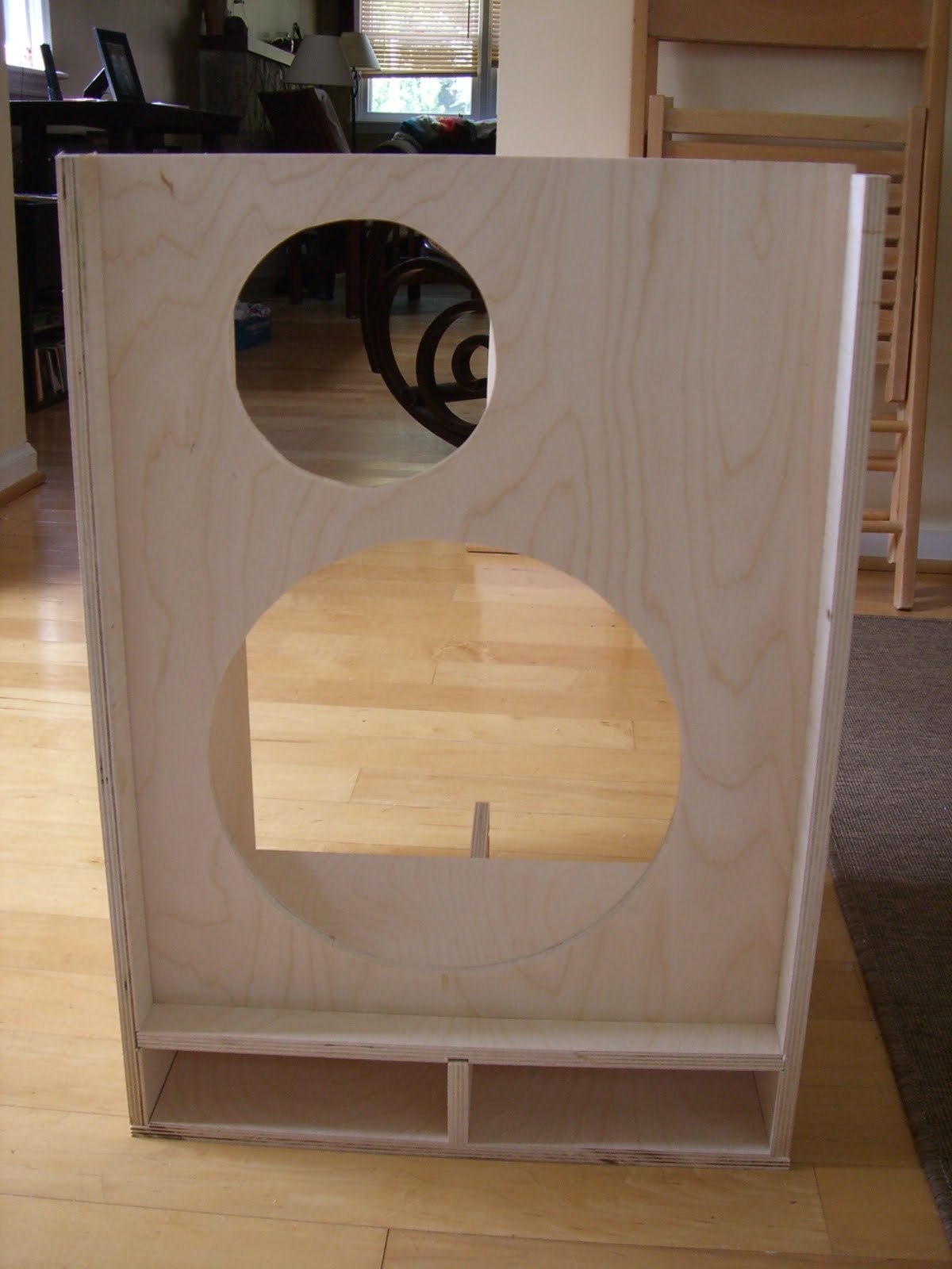
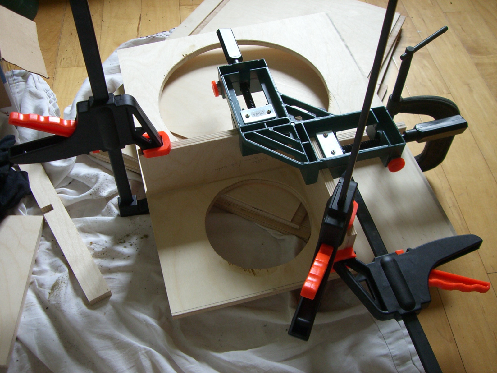
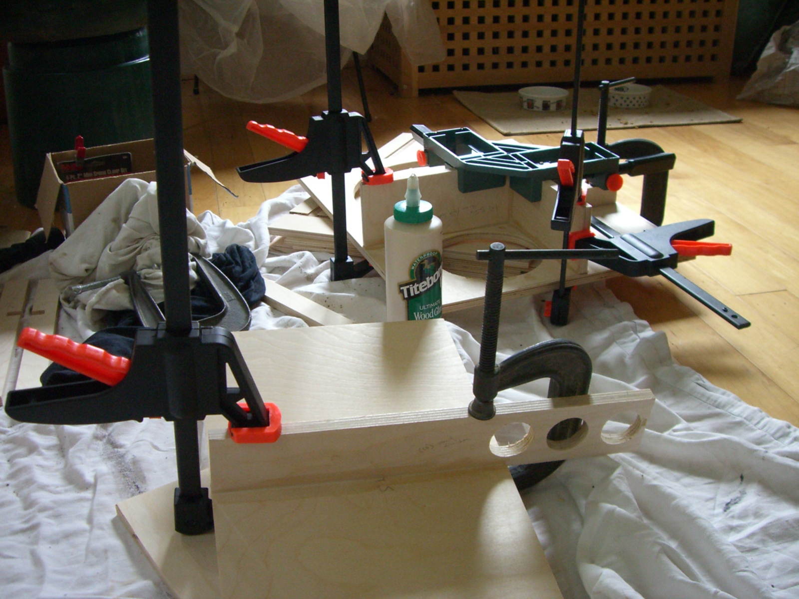
So, I started by gluing/clamping the mid-driver box (side and bottom only) onto the back of the baffle, the spine and sidewall supports on their respective walls, and the port divider to the port shelf. I used green label titebond ultimate ([Invalid or Expired Link Removed]) (NOTE: this glue dries pretty dark. i think the red or blue label varieties might dry a little lighter in color) . The mechanical drawing of the system (Link Removed) was very helpful. I thought about trying to shift the port shelf back a bit to accommodate a grill cover going all the way down to cover the port, but decided to stick with the standard plan this time.


Dry fit (aka, "oh, that's where that goes":confused:)
CIMG2285.jpg


thank you harbor freight :hiding:
CIMG2298.jpg


CIMG2301.jpg


I measured out the placement for the braces (rear and sides) as accurately as possible so they'd line up together when assembling the whole box (EDIT: there was still some misalignment which required trimming later). After laying them out and measuring, i drew a pencil outline for where the brace went. Then I glued and clamped.
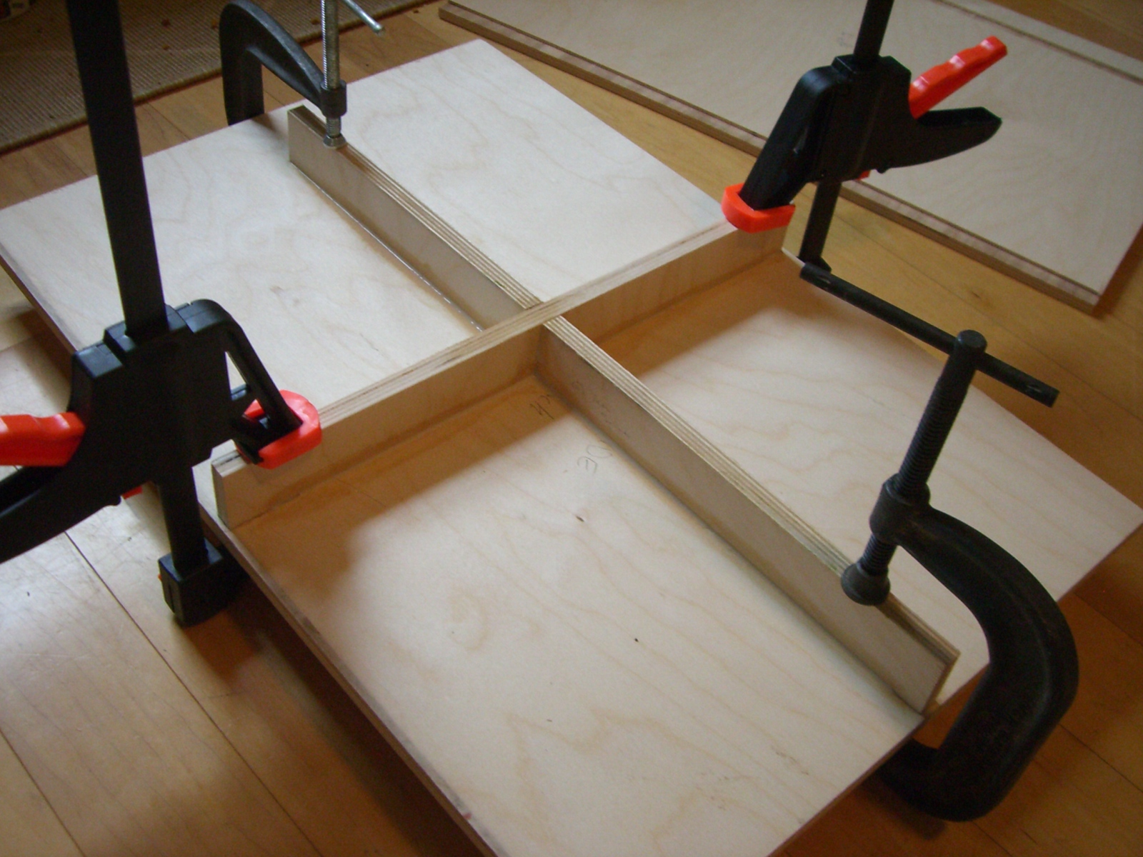
CIMG2309.jpg
 
cool. glad y'all are interested. hopefully you can avoid the mistakes i'm making...do'oh!

here's the next installment.

The crossover

While the first pieces of the box were drying, I got to work on the crossover. There are only 4 components in the "cheap but good" crossover but it still pays to really plan ahead. I guess mine turned out ok but some of the wires were a really tight fit. I mounted the components on ¼” thick pine and soldered them together using 12gauge speaker cable. This was probably way overkill and it was a little hard to bend the thick wires around the small board. I should’ve used smaller cable or had a larger board. erseaudio.com has a slick "2-way crossover" board (Link Removed) that probably would've made it a lot easier...but anyone building their own speaker cab probably isn't putting a premium on "easy".

By the way, does anyone dab a little superglue (or something else) on the terminals to keep them from unscrewing during slamtastic bass thumping?

laying out the crossover component positions

CIMG2306.jpg


strapping 'em in before soldering (pencil for scale)
CIMG2307.jpg


final product. ready to bolt into cab.
CIMG2314.jpg
 
By the way, does anyone dab a little superglue (or something else) on the terminals to keep them from unscrewing during slamtastic bass thumping?

I don't know about gluing, but you have a lot of exposed wire there ahead of your solder joints. If those make a contact you could short the circuit, depending on which wires we're talking about, that could be very bad.

It's always best to remove as little insulation as possible. You might try wrapping the exposed wires with electrical tape, or take the wires off and redo them.
 
I don't know about gluing, but you have a lot of exposed wire there ahead of your solder joints. If those make a contact you could short the circuit, depending on which wires we're talking about, that could be very bad.

It's always best to remove as little insulation as possible. You might try wrapping the exposed wires with electrical tape, or take the wires off and redo them.

The inside of a point-to-point wired amplifier is all exposed wires, even turret board amps have a good deal of exposed wire and those circuits see an awful high amount of voltage and work just fine for decades. The crossover should be ok, the wires on that cap are fairly stiff and I don't see any wires that look like they're in danger of shorting. I can't imagine any amount of vibration would have those wires move enough to do any damage.

The cable ties pass through holes drilled in the piece of wood so it looks like they are being held in place nicely between that and the glue.
 
By the way, does anyone dab a little superglue (or something else) on the terminals to keep them from unscrewing during slamtastic bass thumping?

I just started a Wiki article on the original Passinwind 12/6 crossover that you'll often see referred to in the earlier fEarful threads. Check it out if you want to see "overkill." ;)

I prefer solder (turret board) connections as pictured in the article, or crimp connectors if I happen to be using pre-made PC boards, but a little blue Loctite might be a good idea for yours if you can keep it out of the electrical connection to the wires. Silicone right on the screw heads might work pretty well too.
 
Assembling the box

I think I should’ve only installed the bracing members after putting the walls on. That way, you can clamp the sidewall brace member towards the baffle. This will align brace properly in this direction. It might also help you align the side braces with the rear brace…in other words, mine didn’t match up very well so I had to trim a couple. :atoz:

I’ve put a few more pics showing my clamping style (note the variable pressure application unit…aka, giant pot of water). I used a C-clamp to press in the t-nuts (one still turned on me and I had to replace it).

assembling sides to baffle (back panel is wedged in place but not glued yet)
CIMG2315.jpg


finishing the mid chamber box

CIMG2323.jpg


pressing in the t-nuts

CIMG2322.jpg
 
I'm digging the VPAU. Seriously ingenious rigging there. :D I've used books, bricks, weights, 1/2" steel plate...whatever is heavy and won't roll.

Your cab is looking great. Glad to see you're taking the time to glue all the pieces up one by one to ensure a tight, straight bond. For t-nuts I usually choose the BFH approach and install them before the baffle board is glued to anything else. Drill the holes, lay the board flat on the floor, center the t-nuts and with a 5-pound sledge give'em one good, flat whack. *wham!* and they're in.

Looking great, Blakelock!
 
Final assembly…testing!

I used spray adhesive to glue the polyfil to the chamber sides and back (2” thick on back and 1” thick on sides) then completed the assembly. Now I have some questions.

Question: is it ok that there are still a few unpadded areas in my box (see pics)?

Question: After building the crossover, my wife asked, “can you test that thing before hooking it up?” what a great question and good idea. So I used a function generator to send a 2V sine wave into the x-over, and measured the mid and woofer output signals with an oscilloscope. Then ramped the input frequency and plotted the output (see plot below). Although the signals cross over near the right place, there is a hump in both output signals near the x-over point. Is this normal? Is it because I didn’t have the actual speaker load attached?

my crossover (with no speaker load)
x-over.jpg


Final, and most important, question:
During my initial testing, the lows sound good but the higher notes sound “trilly” or “warbly”. When I play Bb or C (3rd and 5th fret on G string), the note sounds “warbly”. It’s like when you're tuning and you play two note together. when they are out of tune, it's warbly. But in this case, I'm only playing a single note! Is this warble because the back of the box wasn’t sealed on yet? (I tried it with the back completely removed and wedged in place and found no change) Could there be something wrong with mid chamber or crossover (the fundamental frequency of these notes is ~100Hz but maybe we hear higher harmonics)? Maybe it’s due to insufficient damping material. Any help?


gluing in the polyfil

CIMG2327.jpg


screwed x-over to the side bracing

CIMG2328.jpg


filling the mid chamber with pulled polyfil

CIMG2329.jpg


final hookup before letting her rip

CIMG2333.jpg
 
Question: After building the crossover, my wife asked, “can you test that thing before hooking it up?” what a great question and good idea. So I used a function generator to send a 2V sine wave into the x-over, and measured the mid and woofer output signals with an oscilloscope. Then ramped the input frequency and plotted the output (see plot below). Although the signals cross over near the right place, there is a hump in both output signals near the x-over point. Is this normal? Is it because I didn’t have the actual speaker load attached?

You must use either the actual speakers or dummy loads to effectively test the crossover's behavior. Some signal generators do not directly drive 8 ohm (or lower) loads gracefully either -- I use a power amp inline in those cases.
 
so, i think i may've figured out the warbling. i removed the mid speaker and ran just the 12". there was no warbling so i knew it was something related to the mid speaker or chamber. and i had forgotten to seal the cable hole :ninja: (thanks foz) i liquid-nails it up and let it dry overnight. this morning i reinstalled the mid speaker and it's much better. i only played it for ~60 seconds but i think it's fixed. i'll try to put some audio and final pics up soon.
 
Interesting, I don't recall sealing up the cable hole on my mid chamber but I don't have any warbling. How much juice are you running into that?

i don't think i was cranking it too much. i got the warbling sound while using my ~200W ampeg microVR and my big boy GB shuttle 9. the shuttle has lots of juice but like i said, i wan't cranking it much. i've continued testing and it sounds fracking fantastic now that i've plugged the hole. oh yeah, and i think i found the resonant frequency of my dining room:p