• TalkBass has been independent since 1998. Add your voice.
    Create a free account to reply to discussions, view embedded media, and browse with fewer display ads.
    Join freeLog in
    Want zero display ads or expanded classifieds tools? Compare plans.

GK rails in a pedal?

Another reason to buy one of these, is the cool factor of that faceplate. Very cool look. FWIW, if I'd had 300 bones, I'd have bought your 36o preamp. Just know that your work is appreciated and admired, even though it might not be purchased. Small consolation, I know, but it is what it is.
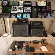
Just finished a batch pedals for some fellow TB'ers.

View attachment 591452
 
So this is probably the only time I'll say this. Is there anyway to top mount the jacks? The jacks being on the outside of a 125b (I'm assuming that's the size?) seems incredibly pedal board awkward. With pancakes I guess it wouldn't be that bad, but just curious.


Also who is selling these? I'm confused about the fuss of "you should buy this only from this person".
 
So this is probably the only time I'll say this. Is there anyway to top mount the jacks? The jacks being on the outside of a 125b (I'm assuming that's the size?) seems incredibly pedal board awkward. With pancakes I guess it wouldn't be that bad, but just curious.

it's in a 1590B, not a 125B, and there's barely enough room to fit everything in it as it is, so top jacks is not an option.
 
Many thanks for this, completely missed that.
Again, apologies if I've missed this, but what does the Distortion Detector part of the Schem refer to?

Many thanks
Si

The distortion detector is an optional circuit that lights an LED to indicate the onset of clipping on the output drivers. It isn't needed for the pedal to function properly.

dist-detector-jpg.jpg

-Frank
 
The distortion detector is an optional circuit that lights an LED to indicate the onset of clipping on the output drivers. It isn't needed for the pedal to function properly.

dist-detector-jpg.jpg

-Frank

Perfect, thanks so much!
So that trace effectively travels from the R13 junction down to the boost circuit (or C3) if the detector isn't implemented?!

Great stuff, popping this into Eagle when I'm back from NYC next week :)

Thanks
Si
 
If it weren't for John prototyping on the west coast, while I was making his life difficult with circuit changes from the east coast, this would have never made it to V5. I have to give huge props to John or anyone else that is willing to play and go the distance with me!

-Frank
 
Perfect, thanks so much!
So that trace effectively travels from the R13 junction down to the boost circuit (or C3) if the detector isn't implemented?!

Great stuff, popping this into Eagle when I'm back from NYC next week :)

Thanks
Si

No. If you do not use the detector, just leave the "Y" and "Z" connections open. Think of the detector as a crude voltage meter...

-Frank
 
I have a few questions...

I've scanned through this thread but haven't seen a sound clip of the effect. Did I just miss it? I'm wondering if it does pretty much simulate the power amp signal hitting the supply rails? My concern is if it would allow a MB amp get that classic GK hard driven sound.

I'm also wondering about kit versions. Are kits with empty circuit boards, all necessary components, cases with artwork, knobs and such available or is anyone considering making them available? I'm thinking like a kit version requiring the assembly and soldering work.
 
No. If you do not use the detector, just leave the "Y" and "Z" connections open. Think of the detector as a crude voltage meter...

-Frank

Sorry Frank, I'm going to ask for you to elaborate here, I'm still early in my electronics knowledge :).
By 'leave Z & Y open', do you instead mean that the output of the boost goes straight to R10s junction and the R13 junction simply straight to pin 3 of the IC?

Again, sorry if I'm missing something basic here

Thanks
Si