

Enjoy the benefits of a premium membership!
Upgrade Account
-
TalkBass has been independent since 1998. Add your voice.
Create a free account to reply to discussions, view embedded media, and browse with fewer display ads.
Join free Log in
Want zero display ads or expanded classifieds tools? Compare plans.
You are using an out of date browser. It may not display this or other websites correctly.
You should upgrade or use an alternative browser.
You should upgrade or use an alternative browser.
Double Bass Homebuilt EUB build thread
- Thread starter Videojunkie
- Start date
-
- Tags
- build a bass diy bass eub
More options
Who Replied?
I am not an electronics expert by any stretch, but I have seen some folks on here that are. Having heard the bass through the guitar preamp, I think I need to get serious about what kind of electronics I want to put into this thing to make the best effect of what I am constructing.
I am strongly considering the Richter PPX5 for this, but at $140 I am wondering if I can get someone to custom make a board based on this A 5-channel mixer / preamplifier for piezo disks by Godfried-Willem Raes wiring diagram with 2.5mm jacks for inputs (so I can just plug in the fishman style piezos) and add a trim pot to blend the 5 channels of piezos.
Or is it possible to "blend" the piezos before the pre-amp and just have a single preamp with the mixed signal going into it?
Then I'd really like to run that output through an at least 2 band boost/cut tone circuit.
I am strongly considering the Richter PPX5 for this, but at $140 I am wondering if I can get someone to custom make a board based on this A 5-channel mixer / preamplifier for piezo disks by Godfried-Willem Raes wiring diagram with 2.5mm jacks for inputs (so I can just plug in the fishman style piezos) and add a trim pot to blend the 5 channels of piezos.
Or is it possible to "blend" the piezos before the pre-amp and just have a single preamp with the mixed signal going into it?
Then I'd really like to run that output through an at least 2 band boost/cut tone circuit.
Last edited:


I don't even know enough to know the difference
 How is this better or different than the circuit above?
I don't even know enough to know the difference
There is a reasonable description of the circuits in each section of that article, but it may not be what you need. Specifically, the bootstrap and charge amplifier designs reduce hum sensitivity, which may not be an issue for you.
Not working on the bass, but marking the cut lines for the bridge and body lines.
I have also decided that one of the vertical bars is likely superfluous and I am going to cut it out. There will be a brace there for the sides and top, plus it is very close to the oversized bridge support.
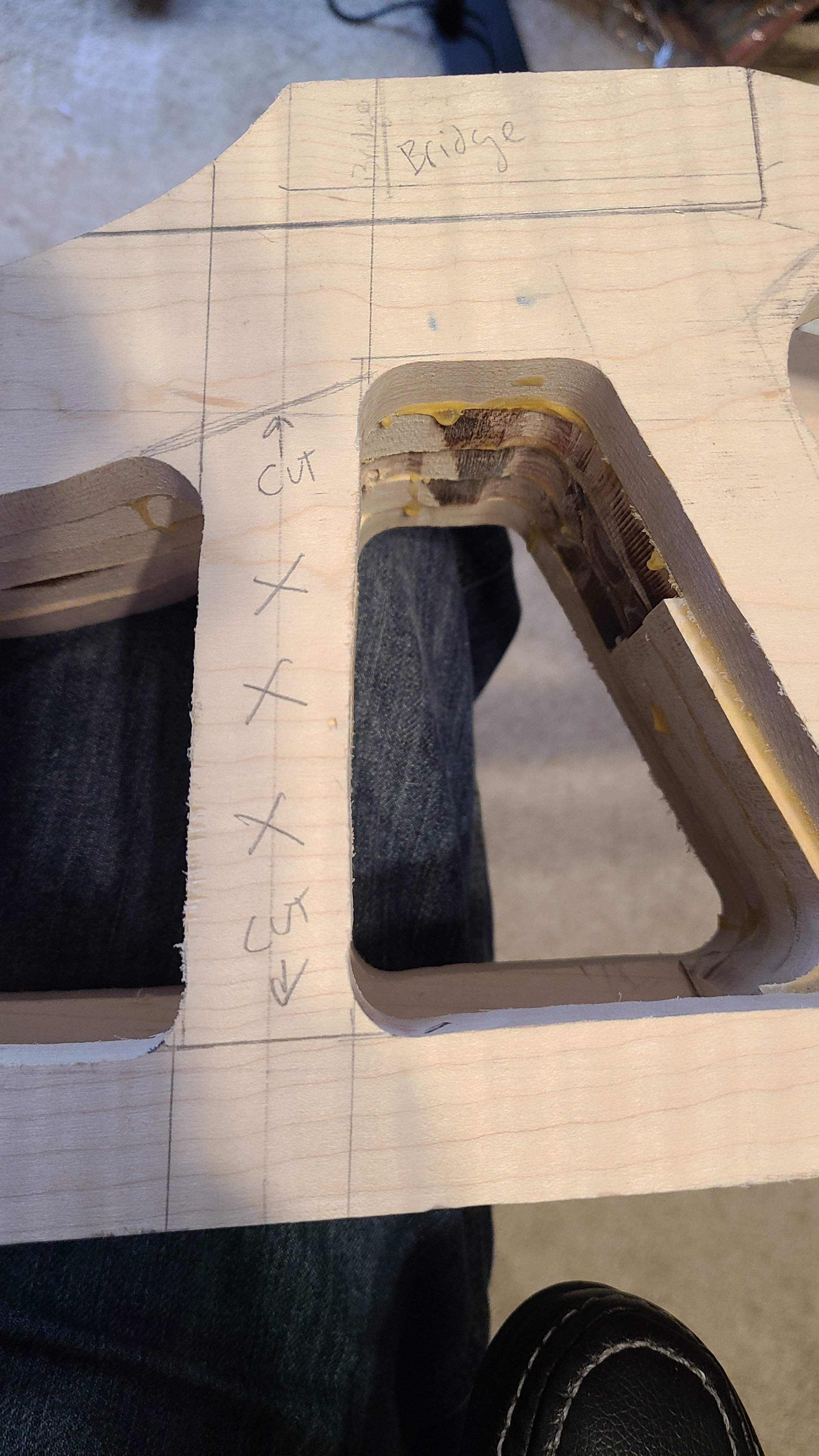
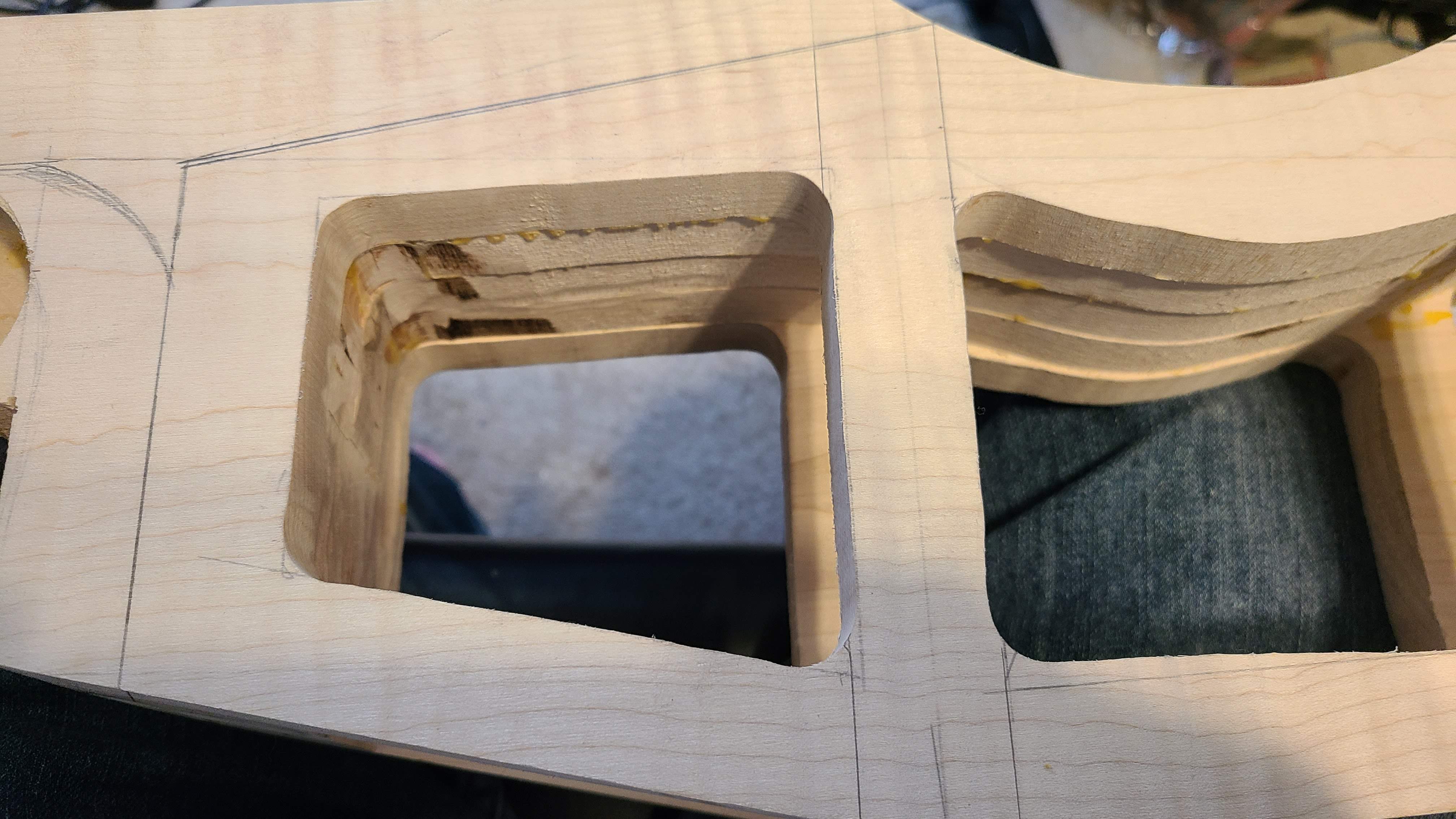
I have also decided that one of the vertical bars is likely superfluous and I am going to cut it out. There will be a brace there for the sides and top, plus it is very close to the oversized bridge support.

Better buffer each string individually and mix afterwards. A buffer only needs a few components and parts are cheap (if you can get a suitable JFET).
Still working on the floor, so no real progress, but I had a few minutes to mess around in the shop.
Test fitting the tuners. I think that's going to work!


Test fitting the tuners. I think that's going to work!
Started cutting out the the side braces. These will get more shaping as I work towards getting the body sorted out.


It's taken a couple of weeks to get the flooring project finished, but I am pleased with the results.
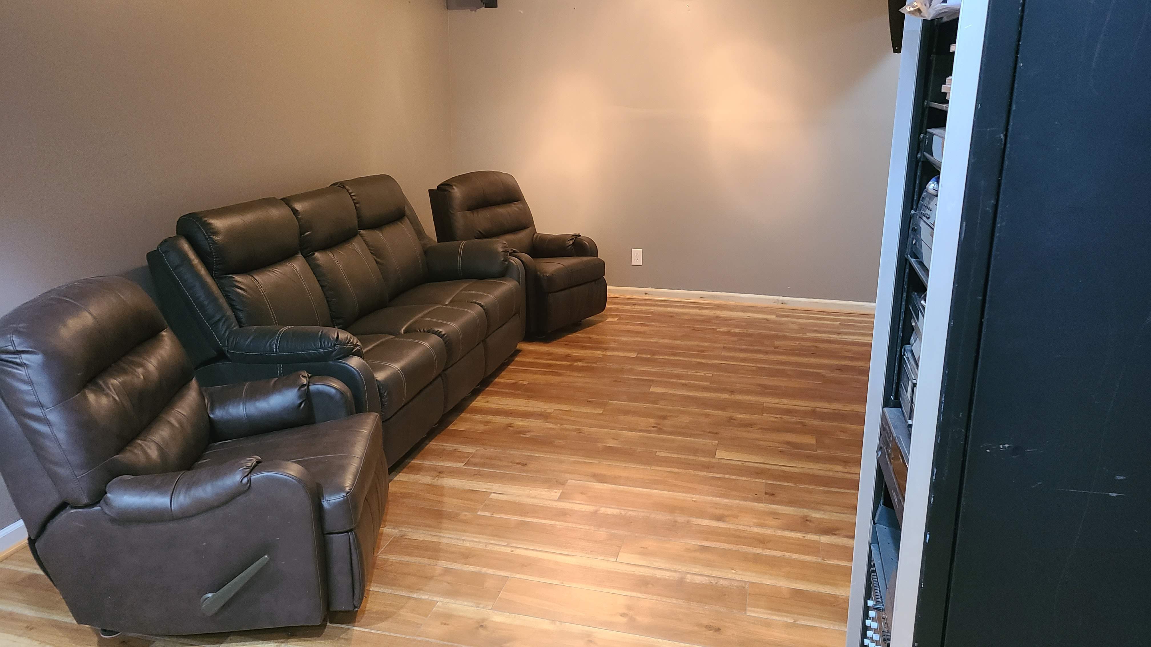
Got a few other things to take care of before I can get back to the bass, but I might work on the electronics a bit more in detail.
Got a few other things to take care of before I can get back to the bass, but I might work on the electronics a bit more in detail.
So, while I haven't been able to make much progress on the bass, I am doing a lot of thinking and reading about how to make the body of this come together.
Originally I was planning on making a skeleton of roughly 3/4" square pieces around all the edges, bevelling the pieces to match all the oddball angles in the design, and then plank the sides with roughly 3/16 - 1/4" thick panels.
While probably the strongest and potentially easiest method to build this, It would certainly compromise the semi acoustic nature of the instrument.
I am wondering if using kerf strips, I might achieve the same goal, and wind up with a livelier acoustic sound. Which is moderately important, as I will not only have the piezo pickup under the saddles, I am also planning a microphone inside the instrument.
In other news, breadboards and components have been ordered for the preamp, and I will start building a 5 channel piezo buffer / preamp system for the bass. First on breadboard and then on pcb. Never attempted any component wiring this complicated before, so I am both excited and a bit nervous. So. Many. Little. Parts!
Originally I was planning on making a skeleton of roughly 3/4" square pieces around all the edges, bevelling the pieces to match all the oddball angles in the design, and then plank the sides with roughly 3/16 - 1/4" thick panels.
While probably the strongest and potentially easiest method to build this, It would certainly compromise the semi acoustic nature of the instrument.
I am wondering if using kerf strips, I might achieve the same goal, and wind up with a livelier acoustic sound. Which is moderately important, as I will not only have the piezo pickup under the saddles, I am also planning a microphone inside the instrument.
In other news, breadboards and components have been ordered for the preamp, and I will start building a 5 channel piezo buffer / preamp system for the bass. First on breadboard and then on pcb. Never attempted any component wiring this complicated before, so I am both excited and a bit nervous. So. Many. Little. Parts!
What the heck was I thinking?!?!
I am hoping this makes more sense when the diodes and op amps show up.
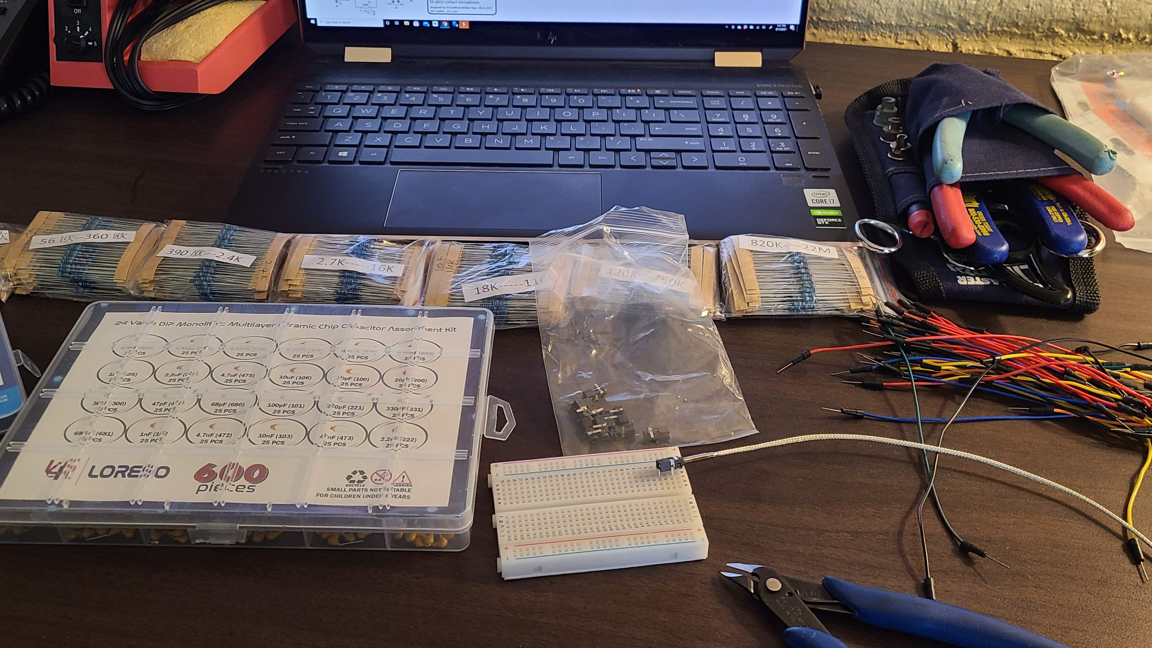
I am hoping this makes more sense when the diodes and op amps show up.
Missing the op amp and some diodes, but it's starting to make sense.
I'm glad I did the breadboard before trying to solder this all on the first go.
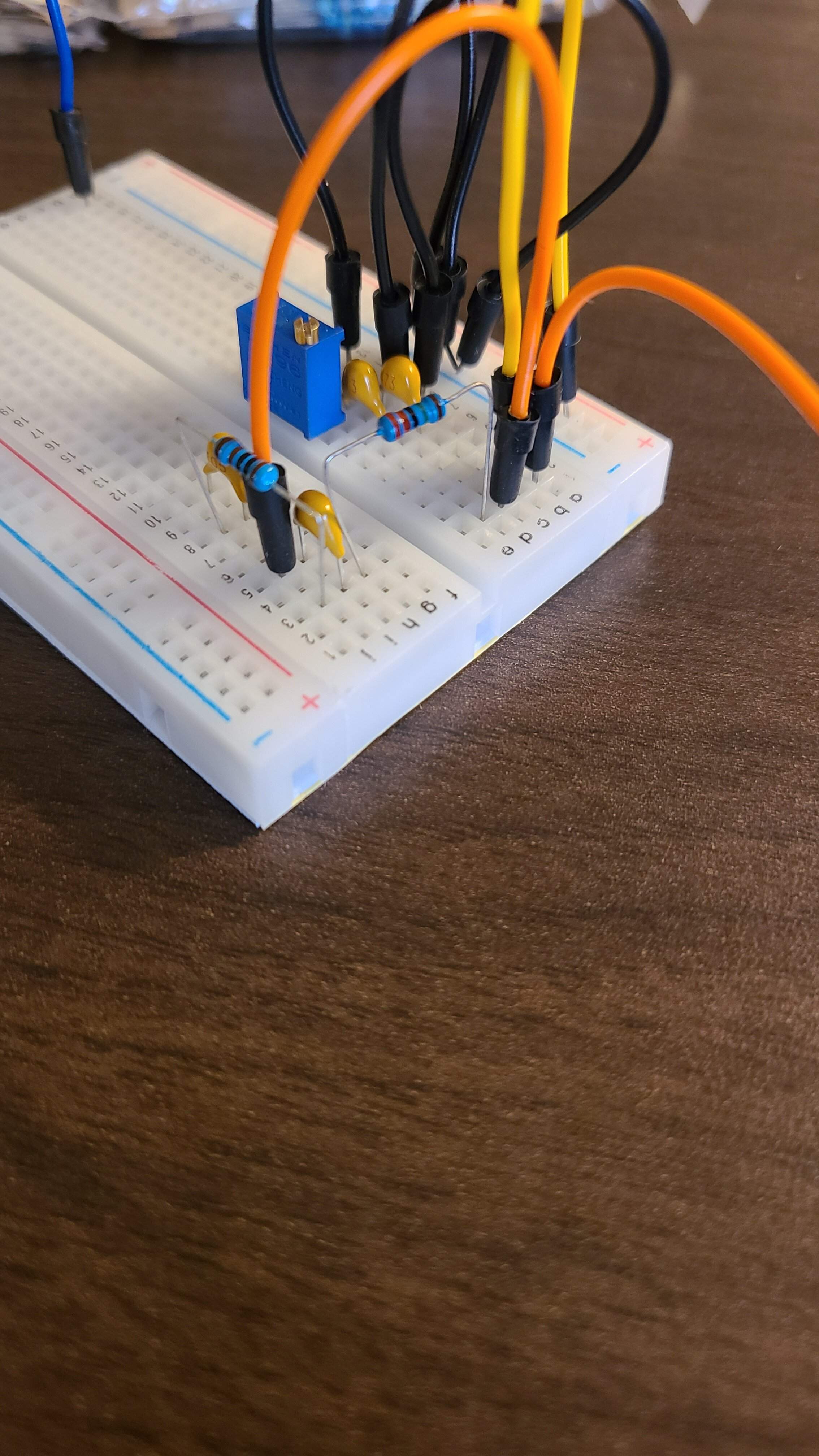
I'm glad I did the breadboard before trying to solder this all on the first go.
Good to see you are doing this on a breadboard because it gives you the chance to see if you like the performance.
About that... I don't want to be the bearer of bad news, but the capacitors you are using (ceramic) are generally not recommended for audio applications. Their capacitance changes with voltage and frequency (i.e.: distortion) and they are somewhat microphonic. This may not matter to your application, and if not you are in luck as MLCC are much cheaper and smaller than film capacitors. Otherwise, replace the capacitors in the audio path with film capacitors.
About that... I don't want to be the bearer of bad news, but the capacitors you are using (ceramic) are generally not recommended for audio applications. Their capacitance changes with voltage and frequency (i.e.: distortion) and they are somewhat microphonic. This may not matter to your application, and if not you are in luck as MLCC are much cheaper and smaller than film capacitors. Otherwise, replace the capacitors in the audio path with film capacitors.
I am not 100% sure I understand which capacitors are the ones in the audio path. Should I replace all of them, or just the ones along what i think is the positive side of the piezo?
Some of them seem like power buffers, and others I honestly don't understand what they are for, as there is a whole series of points that seem to randomly connect capacitors and resistors to ground.
This is the circuit I am working from:
A 5-channel mixer / preamplifier for piezo disks by Godfried-Willem Raes
Some of them seem like power buffers, and others I honestly don't understand what they are for, as there is a whole series of points that seem to randomly connect capacitors and resistors to ground.
This is the circuit I am working from:
A 5-channel mixer / preamplifier for piezo disks by Godfried-Willem Raes
good news, there a limited number of values that I would need. bad news, there's a lot of them!
The best news would be to not need any of them so definitely try what you have first. If you are building the version with the clamping circuit you can probably use MLCC there also.
If you do have to switch some to film, it looks like the 47 uF, 100 nF and 47 nF caps could stay MLCC.
If you do have to switch some to film, it looks like the 47 uF, 100 nF and 47 nF caps could stay MLCC.
Last edited:
The best news would be to not need any of them so definitely try what you have first. If you are building the version with the clamping circuit you can probably use MLCC there also.
If you do have to switch some to film, it looks like the 47 uF, 100 nF and 47 nF caps could stay MLCC.
I am building the 5 channel version. I think that one has the circuit that you are referring to?
Latest posts
-

-

-
 Eden Nemesis vs World Tour tone - Why did I like the Nemesis better?
- Latest: staccatogrowl
-

