
I do not think they had a cover over the power amp circuit board.
As far as I know, they didn't have the cover initially. Same with the chassis back bottom plate.

TalkBass has been independent since 1998. Add your voice.
Create a free account to reply to discussions, view embedded media, and browse with fewer display ads.
Join free Log in
Want zero display ads or expanded classifieds tools? Compare plans.
I do not think they had a cover over the power amp circuit board.

As far as I know, they didn't have the cover initially. Same with the chassis back bottom plate.

I'll third it. Mine doesn't have the cover and it used to not have the back plate till Fliptops did a run of replicas and I bought one thinking it belonged thereI'll second this. I have two '69 SVT's and neither has either.

Yeah older aluminum chassis ones usually have the screws holding the standoffs in from the top so don’t look like they had covers originally.
I have several pics from old ones I’ll go through and see.
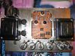
I'll third it. Mine doesn't have the cover and it used to not have the back plate till Fliptops did a run of replicas and I bought one thinking it belonged there
Can't say it's ever been an issue for me.It's a little frustrating that one of the earmarks of an early SVT is the missing back plate.
Serial numbers on the chassis? Long gone.To those who have the unpainted chassis with the TDR (or without), what are your serial numbers on the chassis itself? Just curious.
To those who have the unpainted chassis with the TDR (or without), what are your serial numbers on the chassis itself? Just curious.
Made it about 90% of the way through the preamp boards this weekend. Found someone changed to a 12ax7 circuit so I switched that back to stock values. Changed out the electrolytics and any resistors that were out of spec. Left in all of the Tropical Fish caps. Deoxit the pots. switches, sockets and rockers as well as used it to clean the boards. Looked over all remaining solder joints that I did not touch as well. Have one resistor on order that I thought I had, but did not so that is the last item to replace as it tested low on the resistance totem pole. Once I get that replaced I will start the reassembly back in the faceplate/preamp enclosure. The tube sockets all look to be in good shape with the shields intact (no shield on the 7 pin), but if need be I have new belton replacements. Need to find something thinner than what I currently use to retension the sockets as the space in these are tight. The switches are not stock on the preamp so they will be swapped out for the correct and matching switches. After this process is done and reassembled I will start on the power section.
Also ordered the PEC boards from OshPark and will see how I like them. Think I mis-ordered so I may have extras lol. It's really cool that the PEC boards in mine are hand labeled in pencil marking "SVT #1" and "SVT #2", I love finding stuff like this in old amps. They will be tucked away for safe keeping.
Have NOS or test as new vintage tubes for the preamp and power section. A variety of RCA, Mullard, GE and a Telefunken will be part of a tube rolling process in the future. Will probably leave the 6550 set-up and decide which way to go with those. Maybe Sovteks or Tung Sols as NOS Tung Sols or GE's are way too expensive. That is still a long way off.
Regarding the power section cover, I picked one up from Fliptops. It feels to be a slightly thinner gauge than the plate for the preamp and power plates for my V4b. However I could be wrong on the feel. Most pics I see of early models dont have them, but for $15ish we'll see if it goes in.
What do you plan to do about the screen voltage so the 6550s will make good power; is there already a mod built into the amp? 265W at 5% THD is a common bench test for an amp designed to run 6550s, with a PT putting out ~350V at Node E. Power will likely be much lower with only 220V at Node E.
To those who have the unpainted chassis with the TDR (or without), what are your serial numbers on the chassis itself? Just curious.
Made it about 90% of the way through the preamp boards this weekend. Found someone changed to a 12ax7 circuit so I switched that back to stock values. Changed out the electrolytics and any resistors that were out of spec. Left in all of the Tropical Fish caps. Deoxit the pots. switches, sockets and rockers as well as used it to clean the boards. Looked over all remaining solder joints that I did not touch as well. Have one resistor on order that I thought I had, but did not so that is the last item to replace as it tested low on the resistance totem pole. Once I get that replaced I will start the reassembly back in the faceplate/preamp enclosure. The tube sockets all look to be in good shape with the shields intact (no shield on the 7 pin), but if need be I have new belton replacements. Need to find something thinner than what I currently use to retension the sockets as the space in these are tight. The switches are not stock on the preamp so they will be swapped out for the correct and matching switches. After this process is done and reassembled I will start on the power section.
Also ordered the PEC boards from OshPark and will see how I like them. Think I mis-ordered so I may have extras lol. It's really cool that the PEC boards in mine are hand labeled in pencil marking "SVT #1" and "SVT #2", I love finding stuff like this in old amps. They will be tucked away for safe keeping.
Have NOS or test as new vintage tubes for the preamp and power section. A variety of RCA, Mullard, GE and a Telefunken will be part of a tube rolling process in the future. Will probably leave the 6550 set-up and decide which way to go with those. Maybe Sovteks or Tung Sols as NOS Tung Sols or GE's are way too expensive. That is still a long way off.
Regarding the power section cover, I picked one up from Fliptops. It feels to be a slightly thinner gauge than the plate for the preamp and power plates for my V4b. However I could be wrong on the feel. Most pics I see of early models dont have them, but for $15ish we'll see if it goes in.
Does anyone happen to have the Molex pin part #'s or dimensions? Purchased a new fan from Fliptops and they sent a new wire/connector.
Working through the connector wires to see what goes where and mine is a little diff than the schematic, but I am reading some may be... #3 and #7 show for F, but my 3 is empty (although mine looks to be in #8.. blueish wire) and #7 is yellow which looks correct.
After this I have the switches to go and the preamp will be done...
The umbilical was wired a couple of different ways. My 70 power amp schematic (Rev C) shows pin 3 was NC and the heaters were wired between pins 7 and 8. My 6550 schematic ( Rev D dated 75 I believe) shows the heaters are wired between pins 7 and 3.
If you are careful you can extract pins from the connector and reuse them.
Those pin assignments were moved around. The ‘71 is the only one that I’ve kept a record of.
View attachment 3255704
Pulled the two fan connectors and was able to pry the two prongs that held the wire jacket in place, but the soldered end is pretty tight and wasnt able to pry thme up yet..
Thank you Beans, this forum is such a great wealth of information! Going to have to look at the power amp side as well to see how they correspond with the preamp side for connector alignment before anything gets powered up on the preamp. Was referencing the connector of a linden, nj schematic and a few pins were off and this confirms it as well. While these types of projects are fun to bring back something like this to a working state, sometimes you want to start pulling your hair figuring out what they did and why they did it.. lol




