

Enjoy the benefits of a premium membership!
Upgrade Account
-
TalkBass has been independent since 1998. Add your voice.
Create a free account to reply to discussions, view embedded media, and browse with fewer display ads.
Join free Log in
Want zero display ads or expanded classifieds tools? Compare plans.
You are using an out of date browser. It may not display this or other websites correctly.
You should upgrade or use an alternative browser.
You should upgrade or use an alternative browser.
Neck for Bass-Adrenaline
- Thread starter Rickett Customs
- Start date
More options
Who Replied?
I'll focus on the cavity again.... Fit and finish work, if you will......
Seems like everything fits, but wait..... some don't. Had to tweak it a bit....
The 6 way rotary switch, is not fitting very well with the new edges, had to dremel it a bit.
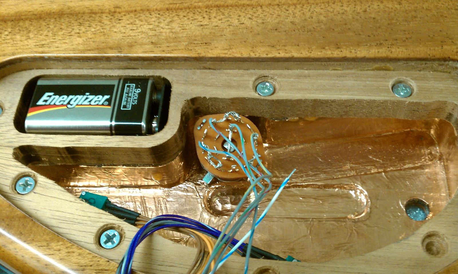
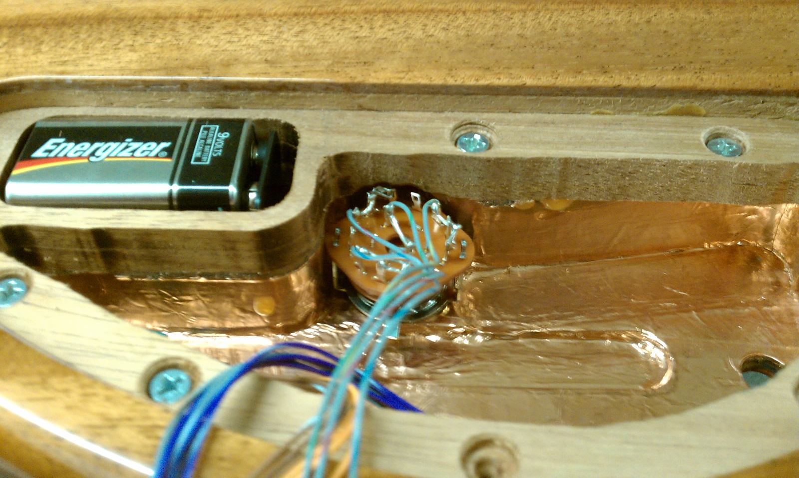
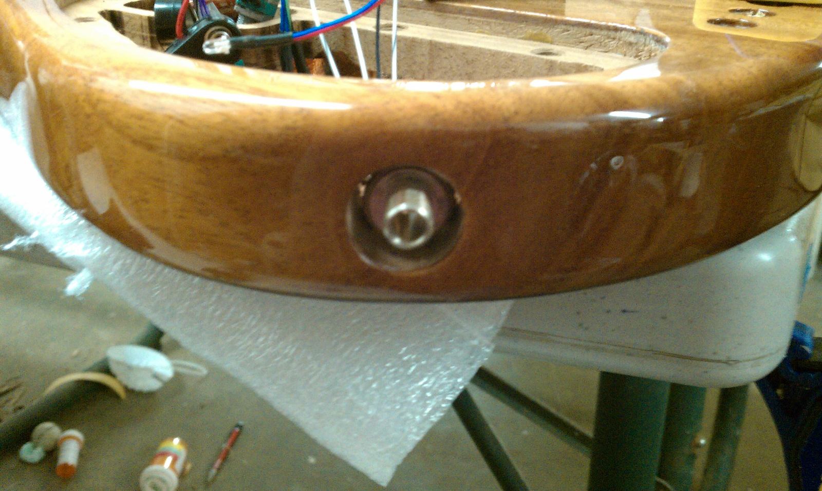
Had to make some more space in the hole for the jack (tele style jack).
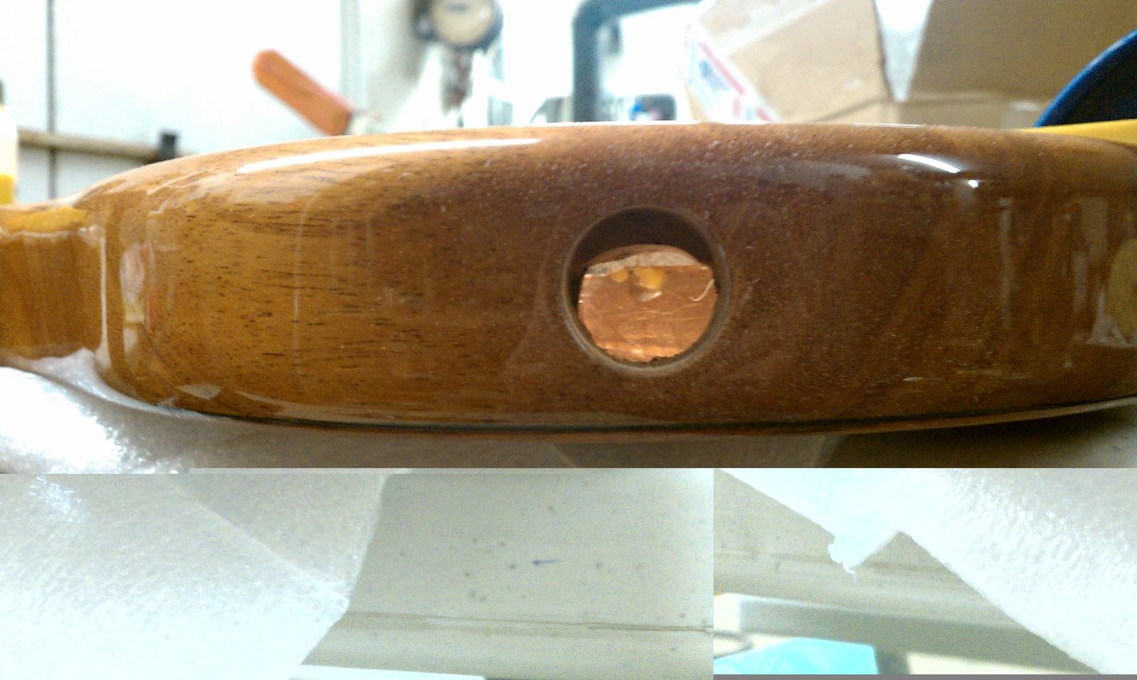
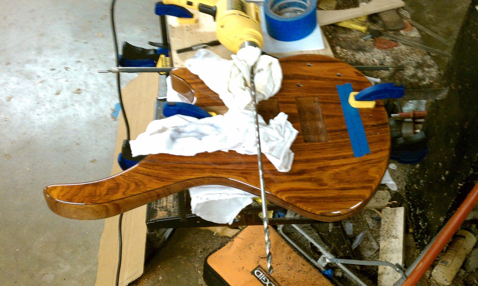
Wanted to re-drill the neck pickup wiring hole, moved it up further in the cavity, so it doesn't have any issues with the rotary switch area. (original location).
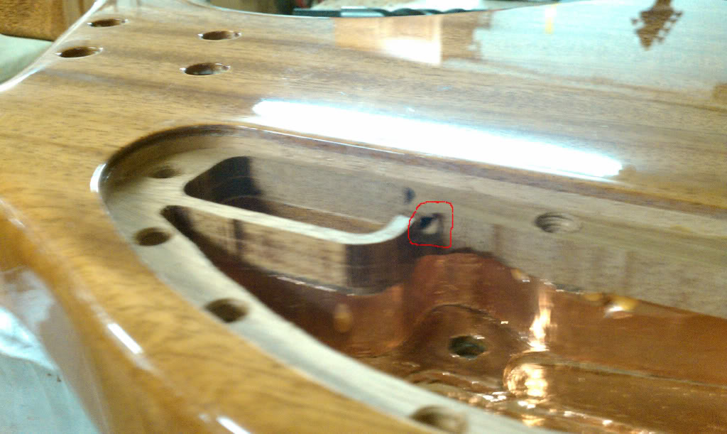
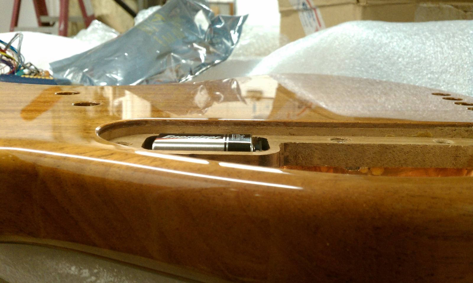
Since this will be 18v electronics, it will obviously be (2) 9v..... Cleaned out the finish overspray, then marked and routed out a little, so that the cover sits flush.
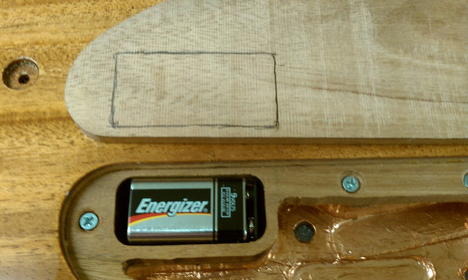
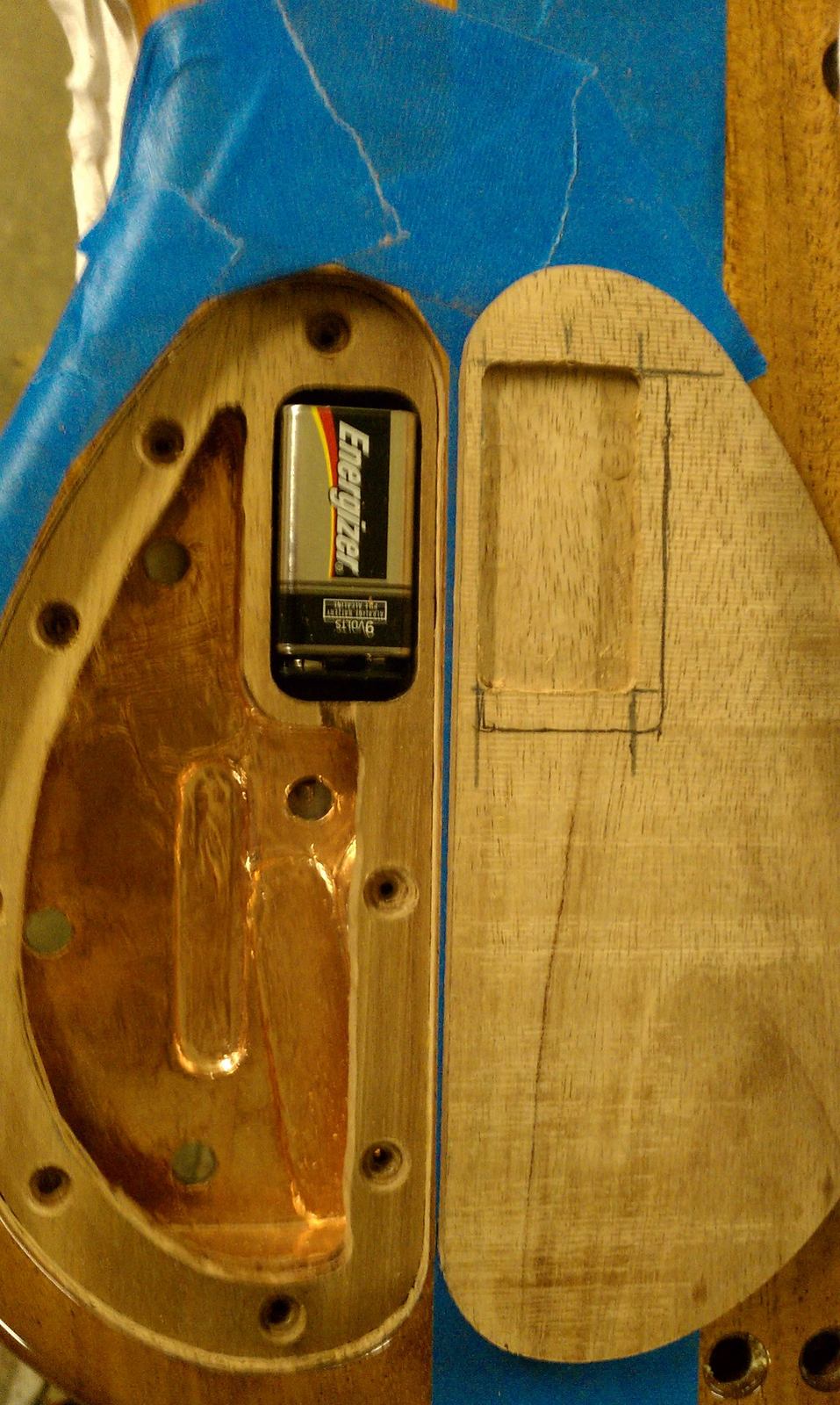
Foiled the lip and edges. put the set screws in.
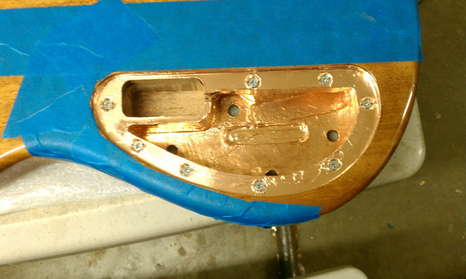
Seems like everything fits, but wait..... some don't. Had to tweak it a bit....
The 6 way rotary switch, is not fitting very well with the new edges, had to dremel it a bit.
Had to make some more space in the hole for the jack (tele style jack).
Wanted to re-drill the neck pickup wiring hole, moved it up further in the cavity, so it doesn't have any issues with the rotary switch area. (original location).
Since this will be 18v electronics, it will obviously be (2) 9v..... Cleaned out the finish overspray, then marked and routed out a little, so that the cover sits flush.
Foiled the lip and edges. put the set screws in.
Looking great! I knew if anything would cause problems in that area it would be that rotoray switch. The pots for that pre amp are so small so that switch seems so out of place. lol
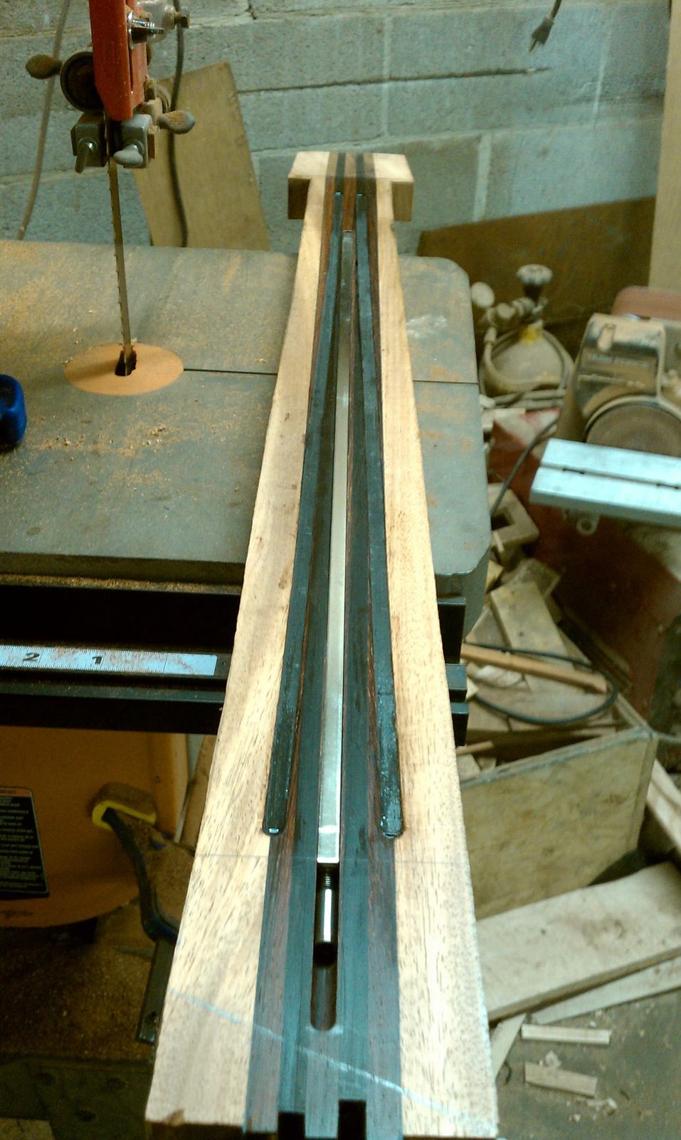
CF rods came in.
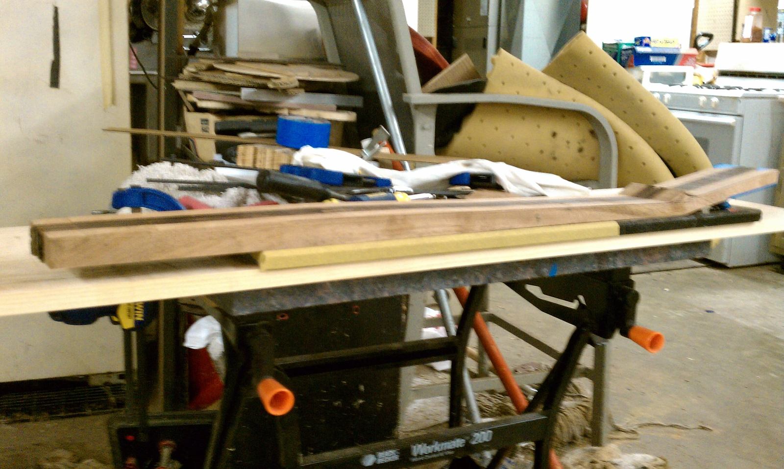
First, I level the the "top" of the neck, I use a piece of granite, with stick-it sand paper and run the neck across it, until we're 100% level.
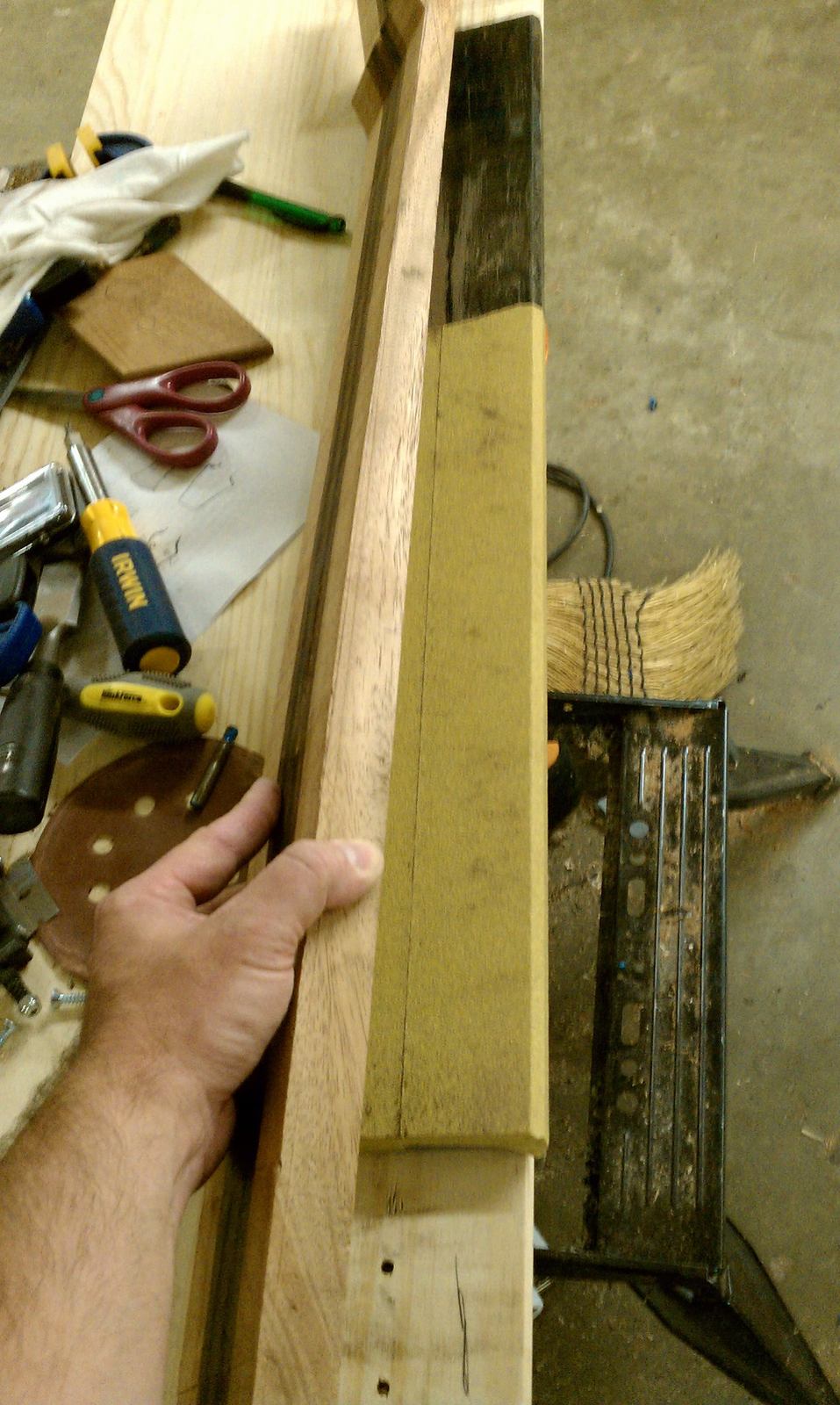
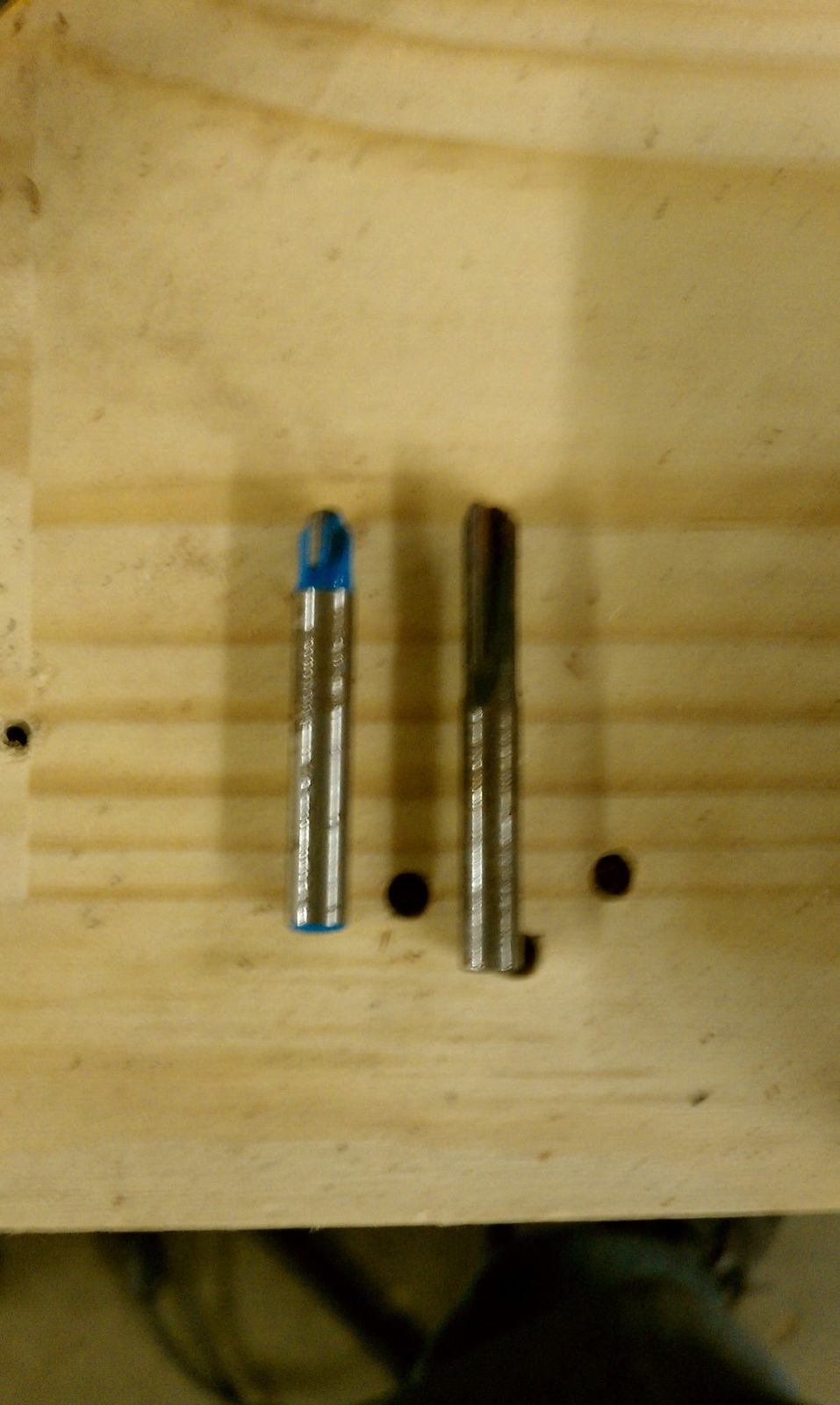
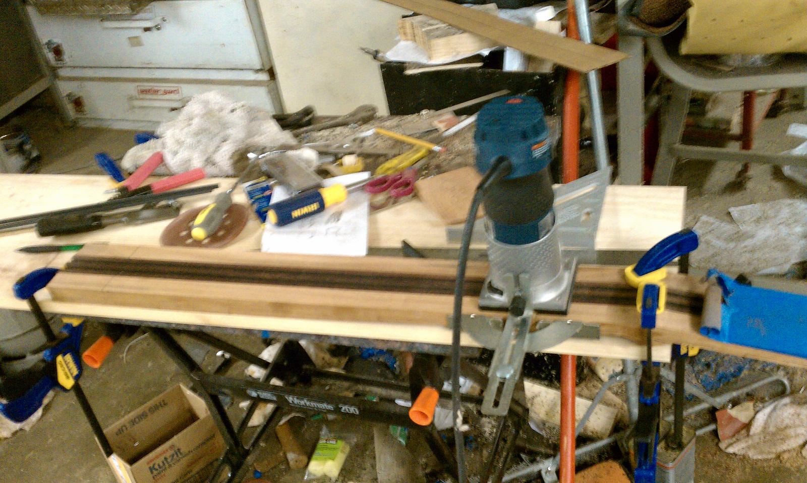
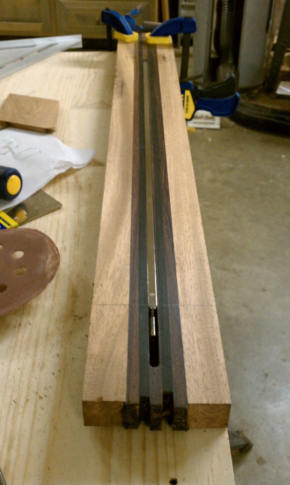
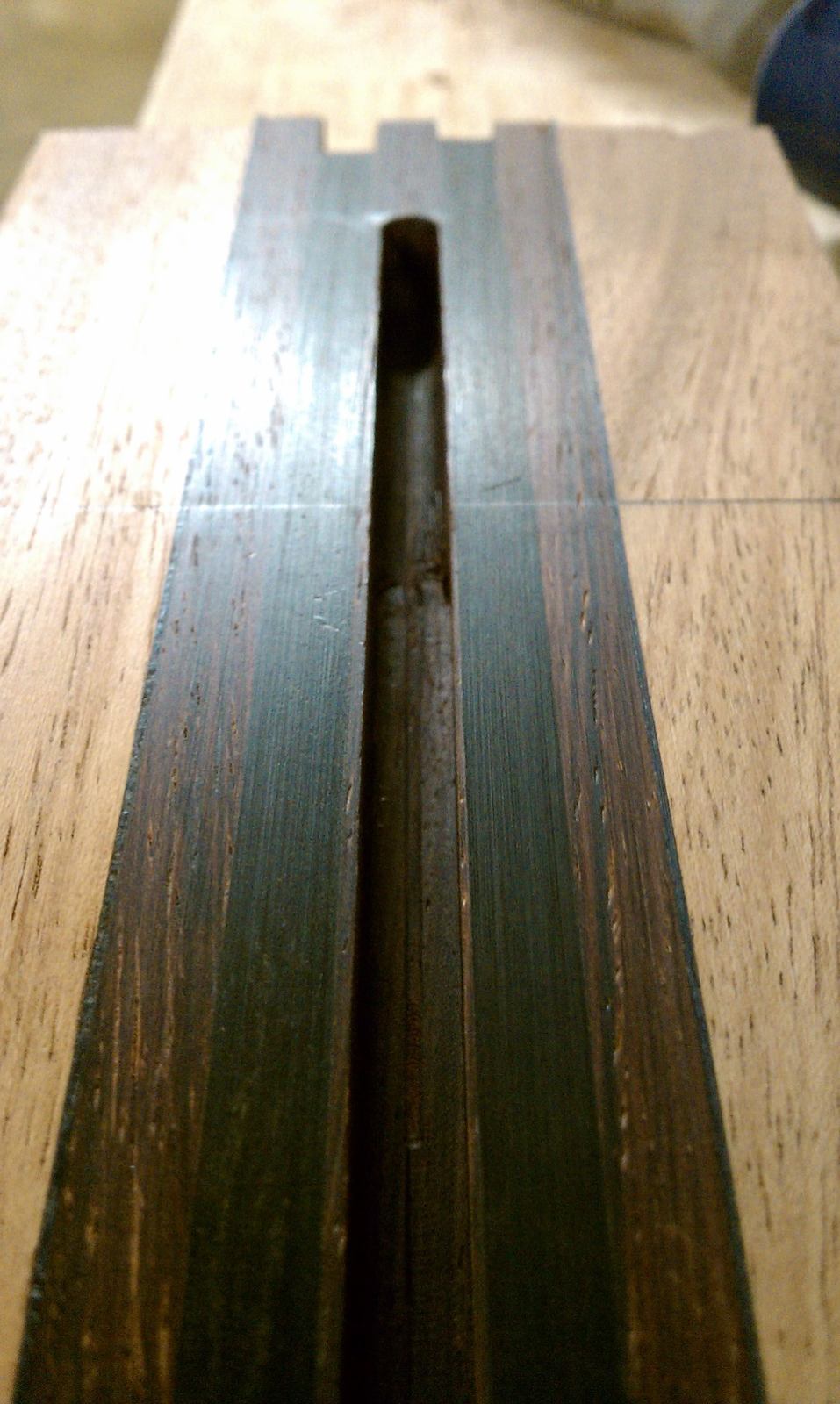
Then I route the trussrod channel..... I use the square 1/4" bit and a 1/4" cove bit, for the rod access.
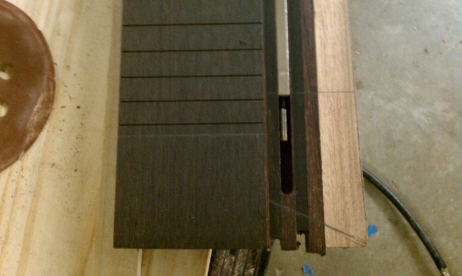
Rough tapered the neck.
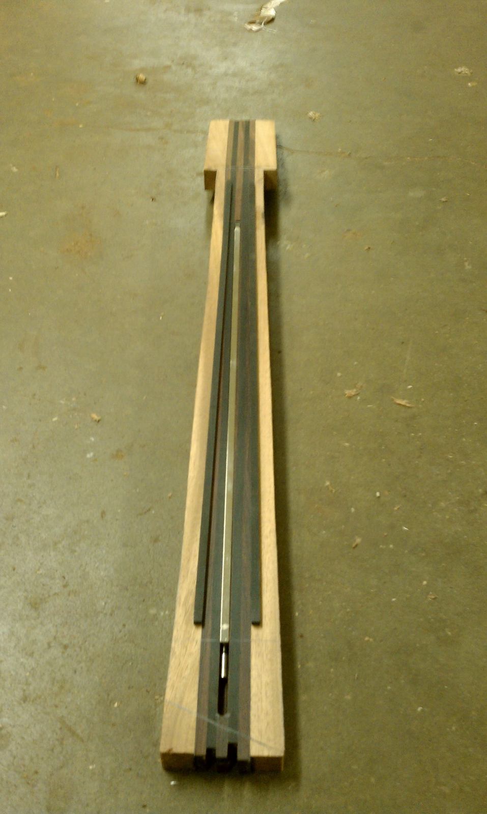
First, I level the the "top" of the neck, I use a piece of granite, with stick-it sand paper and run the neck across it, until we're 100% level.
Then I route the trussrod channel..... I use the square 1/4" bit and a 1/4" cove bit, for the rod access.
Rough tapered the neck.
Took care of the CF rods and epoxied them in the slots...
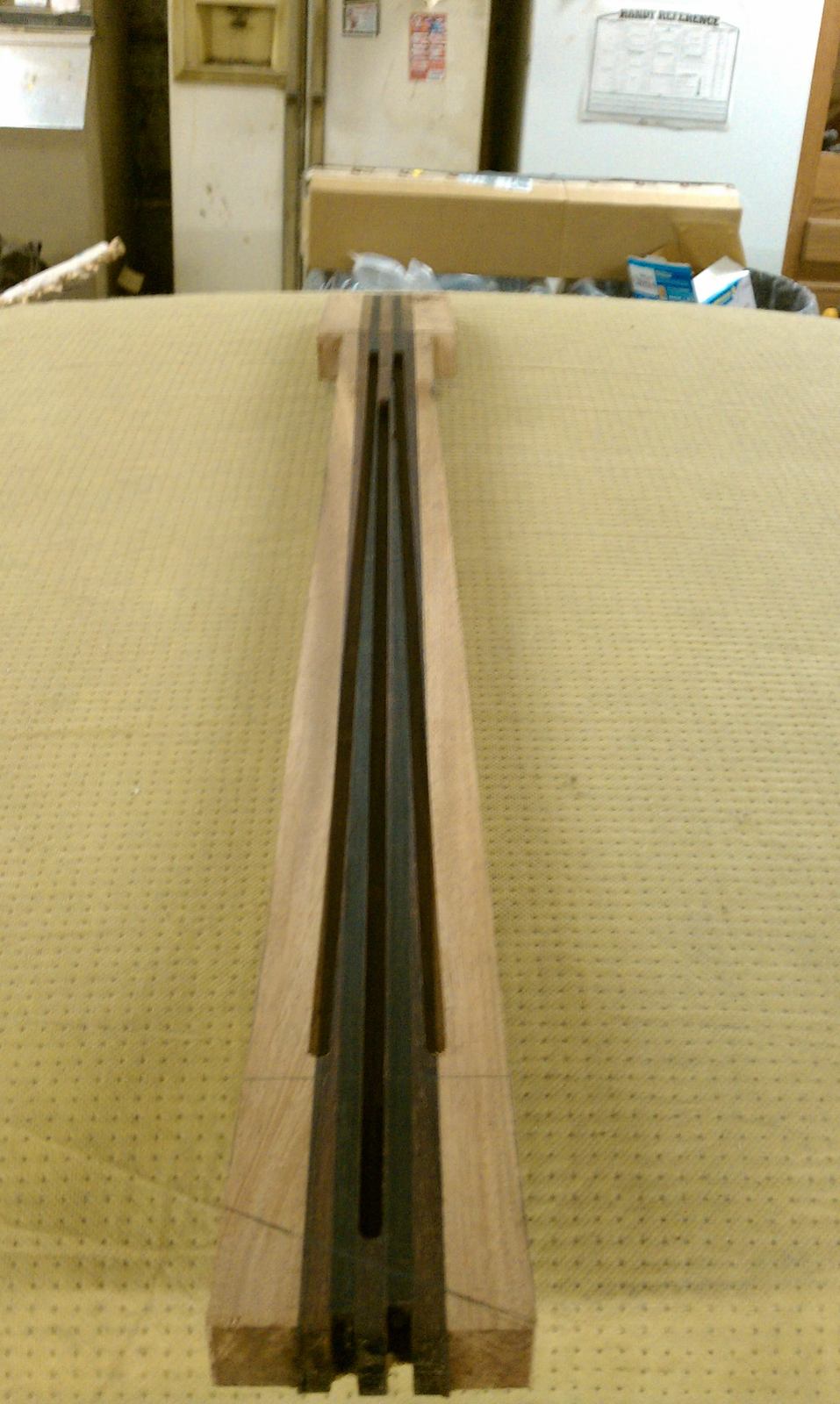
Then got the slot done for the cavity access, the magnets and foiled the cover.
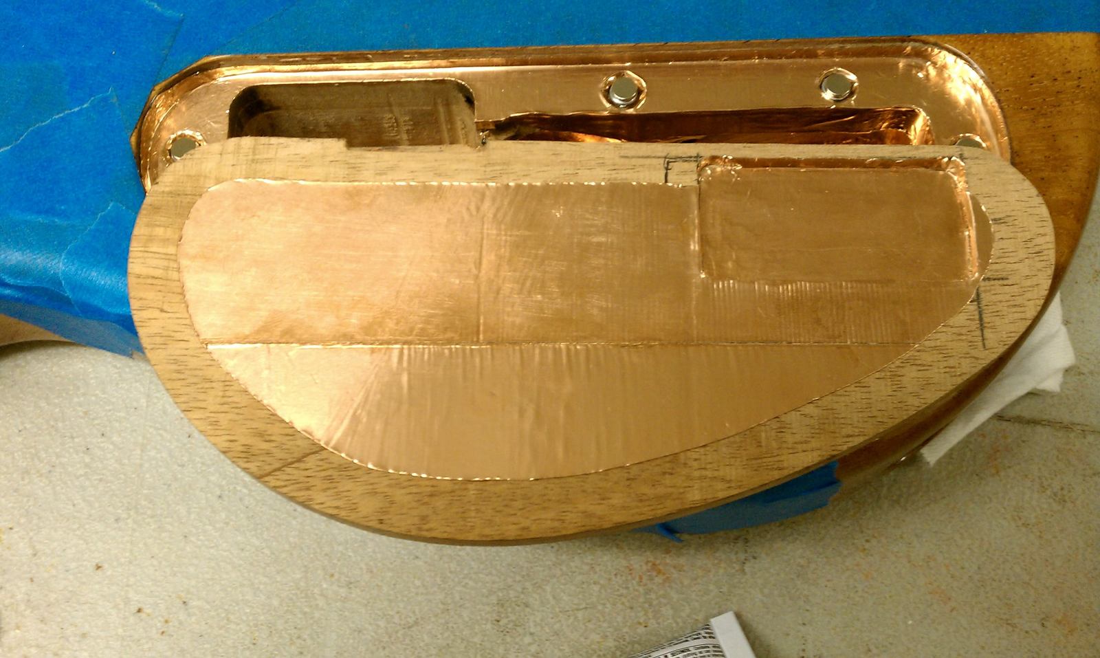
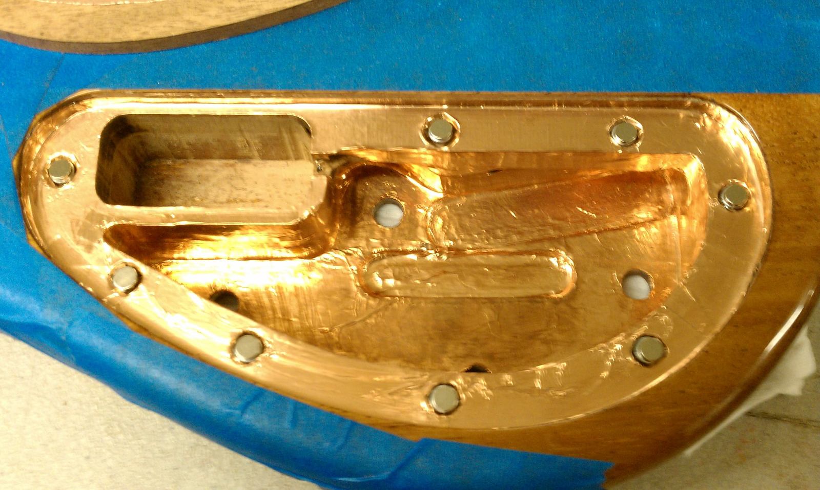
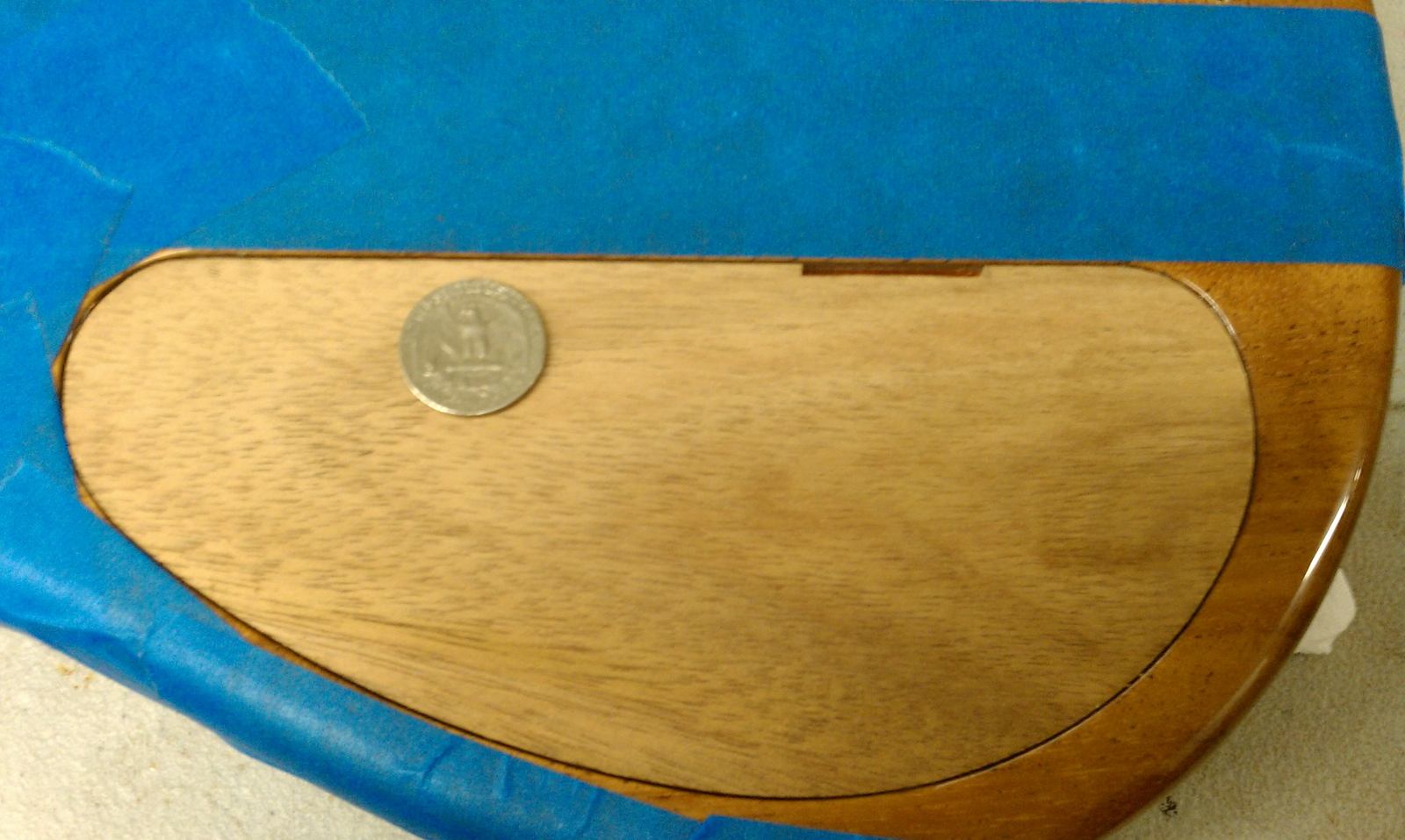
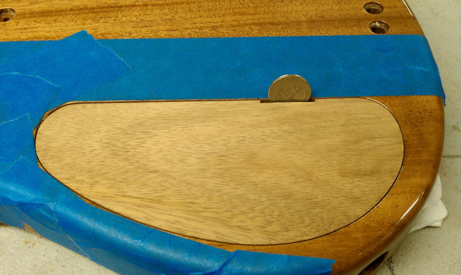
Then got the slot done for the cavity access, the magnets and foiled the cover.

Well, that's certainly both a novel way to hide a battery and a novel way to pop the electronics compartment. Cool stuff there. 

What?? So you need money to change the battery?? That's an expensive bass to own.
Coin operated, if you will....... except you won't get a bag of chips here
More fun.......
Since the cavity cover is getting closer to done, I darkened it up slightly with tru-oil and the next destination for the cover is my finish man. It'll deepen the color with some finish on it.....
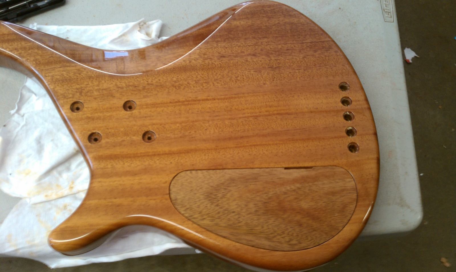
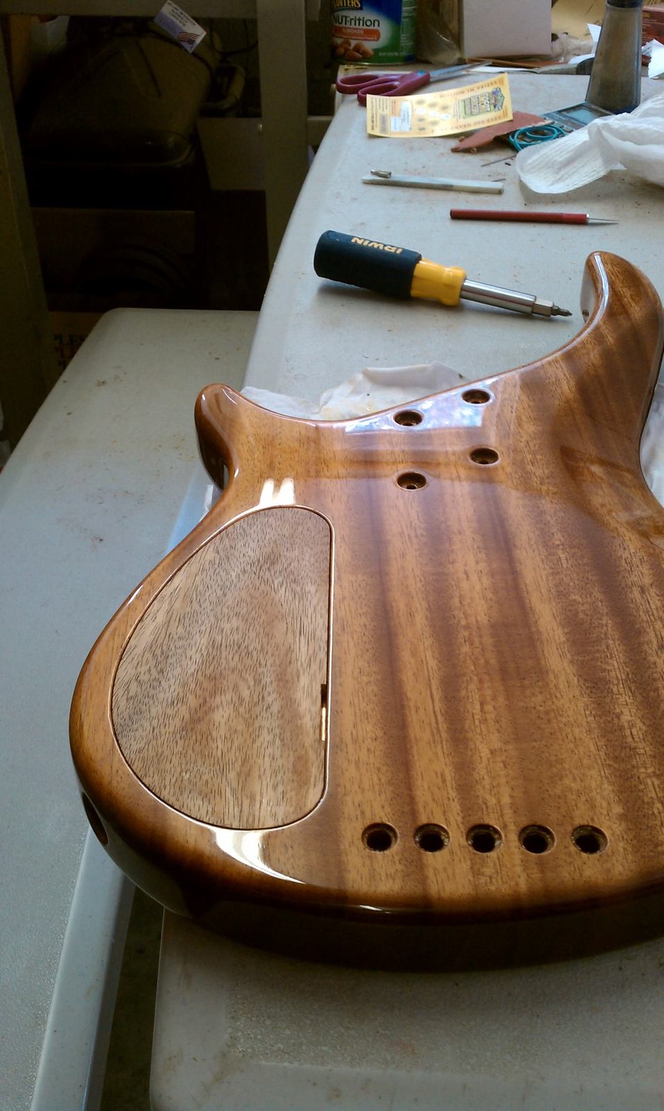
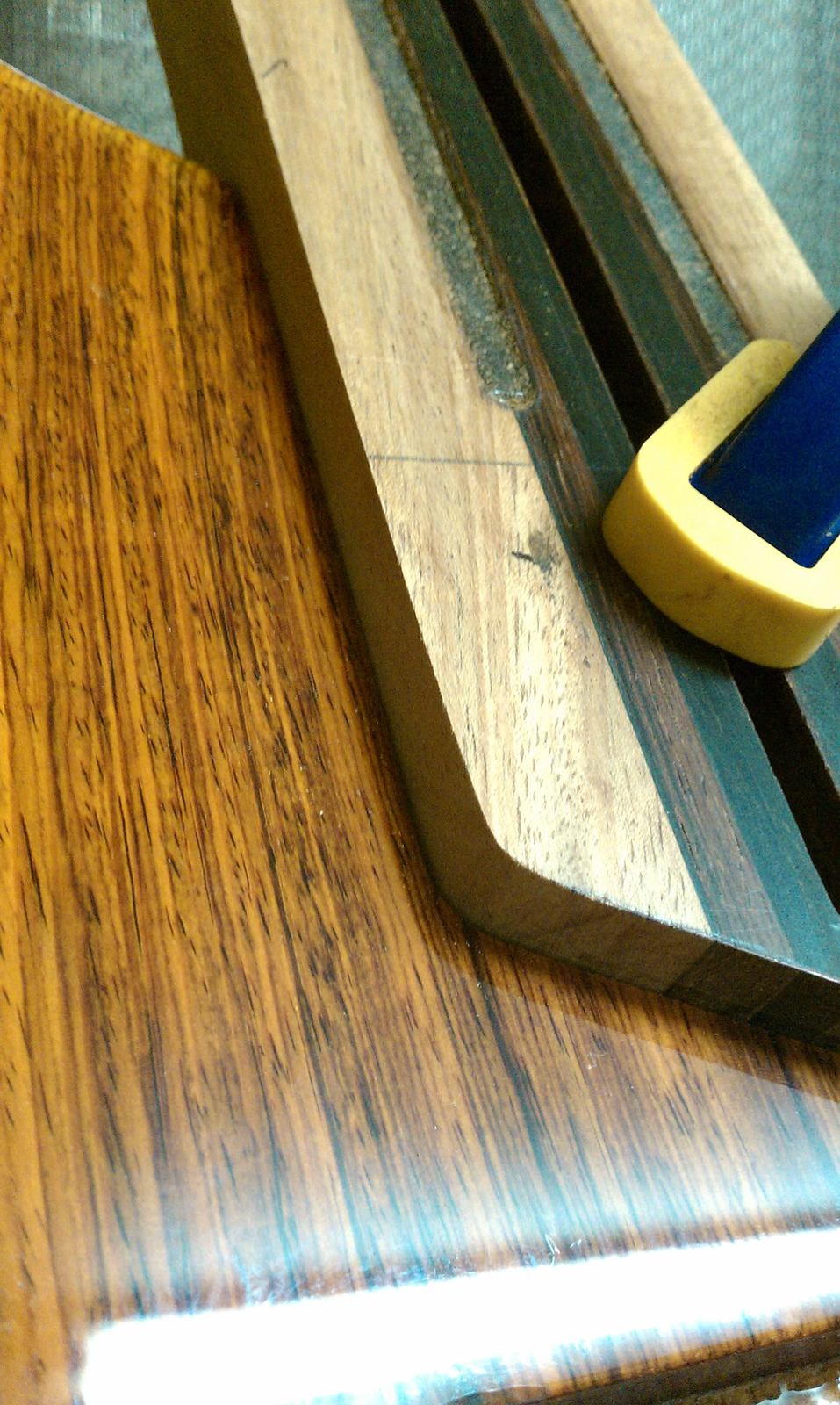
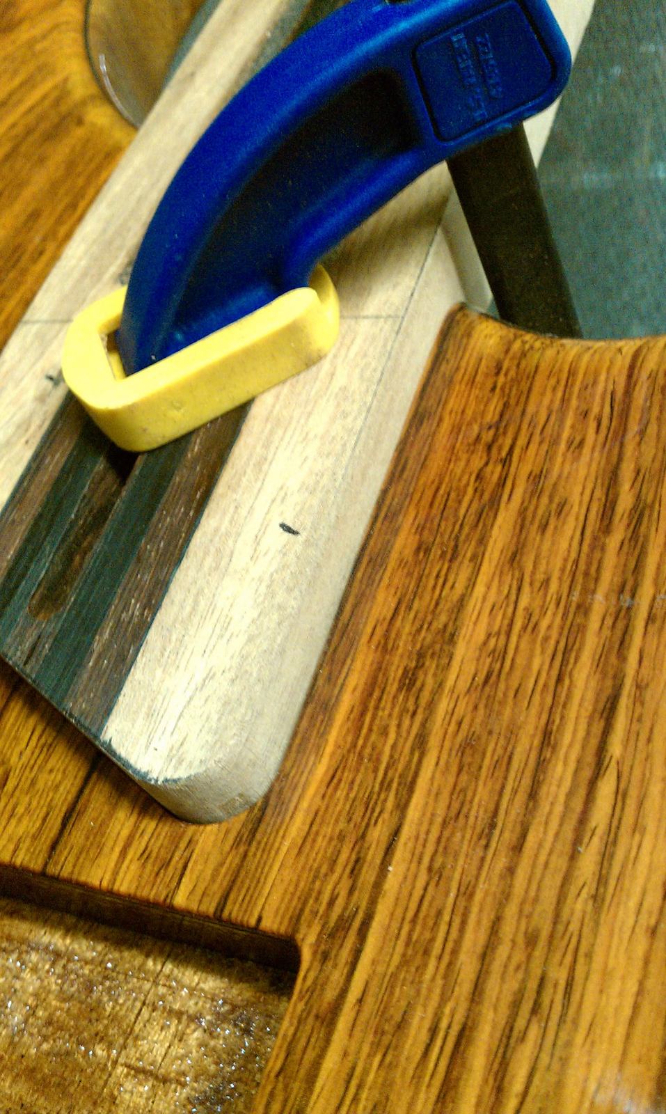
I trimmed up the edges of the neck and fitted it to the pocket.
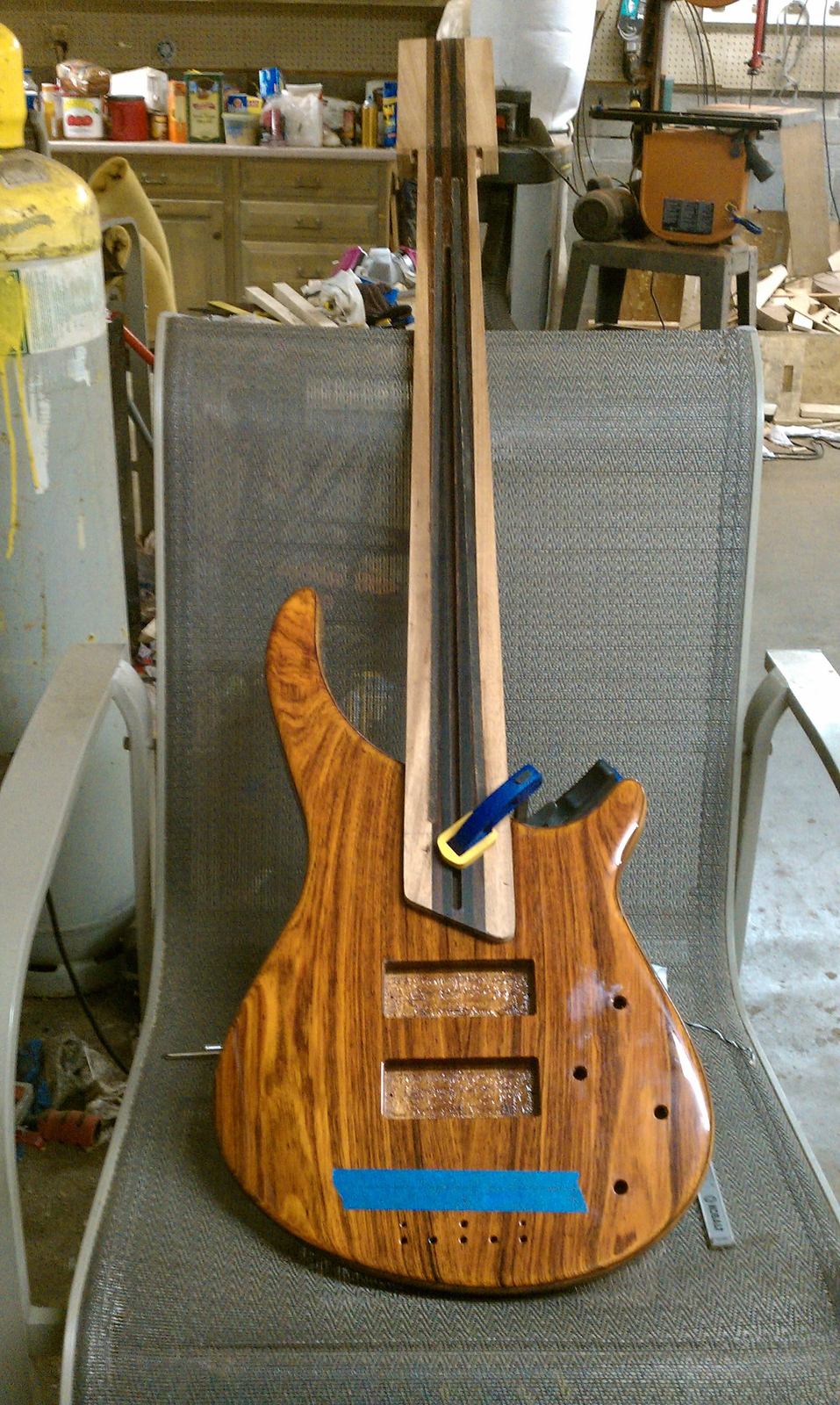
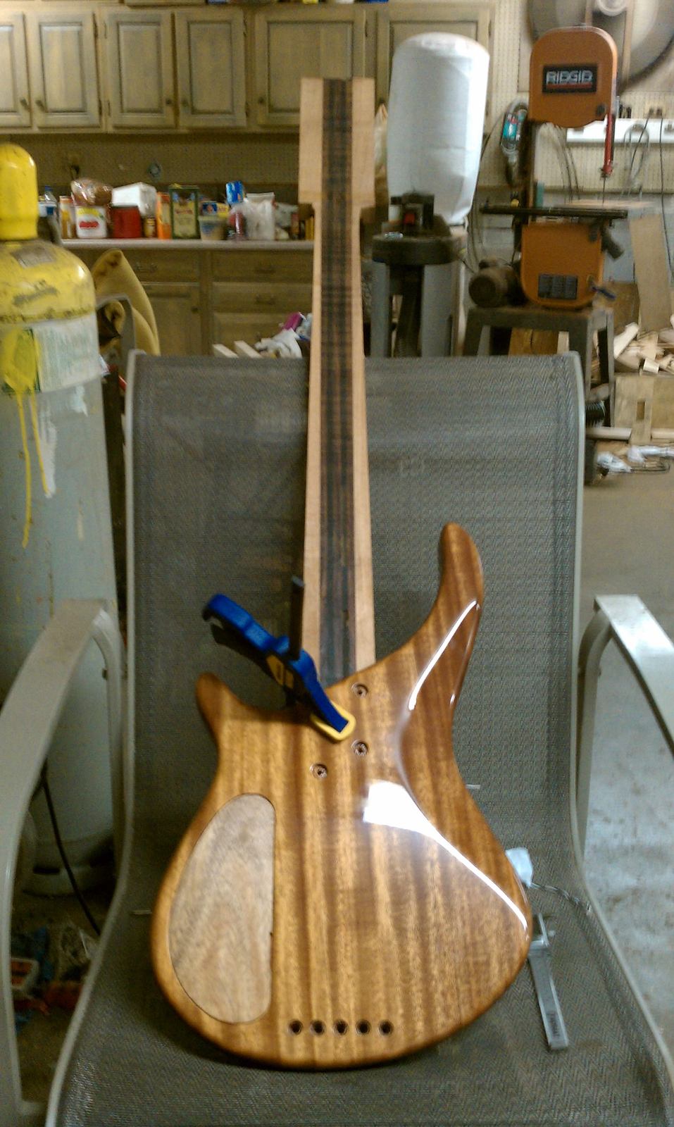
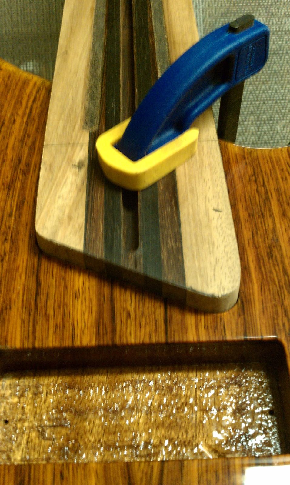
Yessir, we're at 35" now. It looks off, but it's actually dead on.
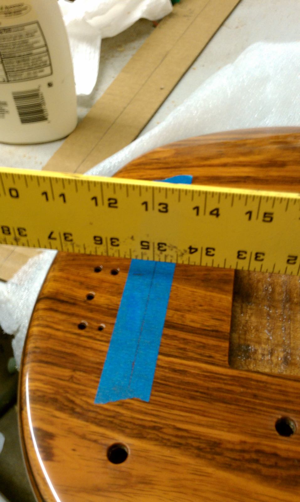
Next will be re-drilling the neck screw holes, to accommodate the machine screws and compression washers.
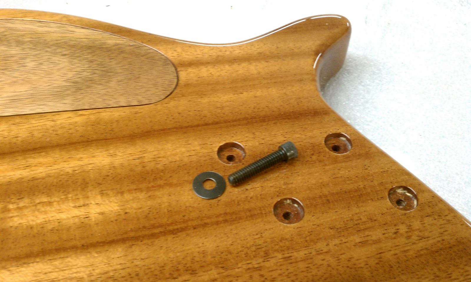
Since the cavity cover is getting closer to done, I darkened it up slightly with tru-oil and the next destination for the cover is my finish man. It'll deepen the color with some finish on it.....
I trimmed up the edges of the neck and fitted it to the pocket.
Yessir, we're at 35" now. It looks off, but it's actually dead on.
Next will be re-drilling the neck screw holes, to accommodate the machine screws and compression washers.
Now, the machine bolts..
Had to make the neck screw hole, a little larger.
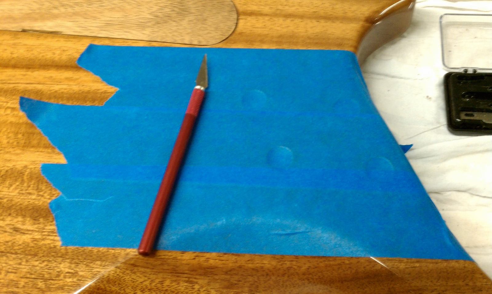
Taped the area off, so I could trace out the compression washers..
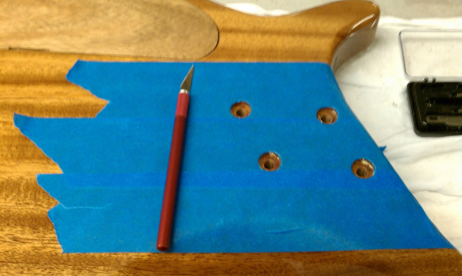
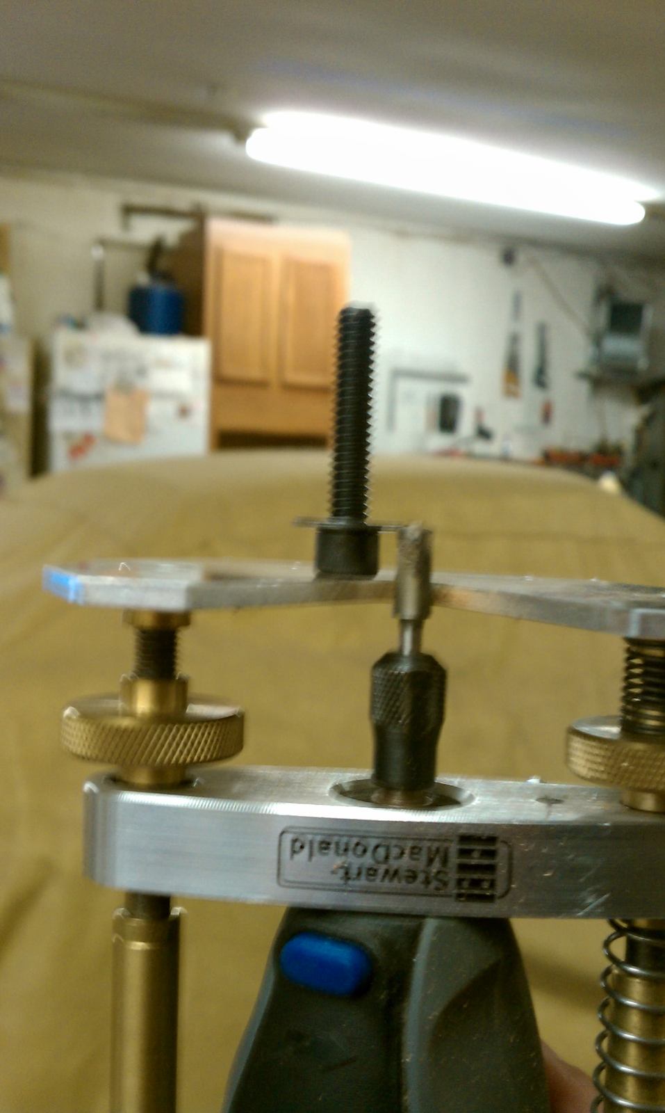
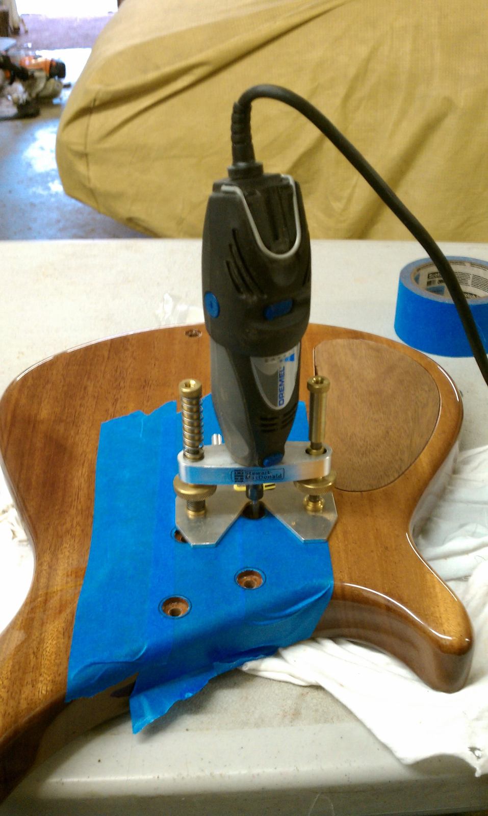
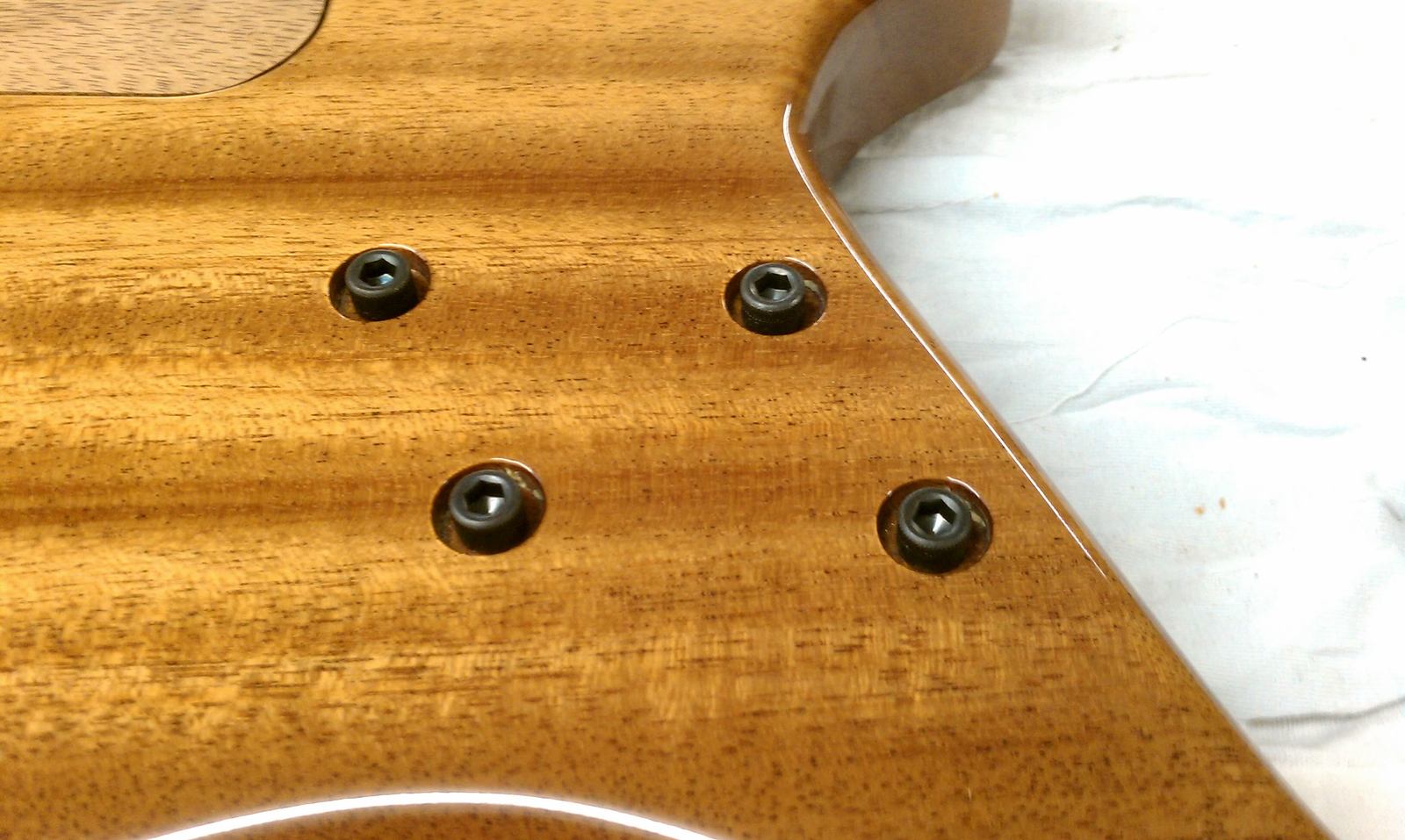
Sizing part done, the larger holes are the right size for the washer to stay in permanent ..
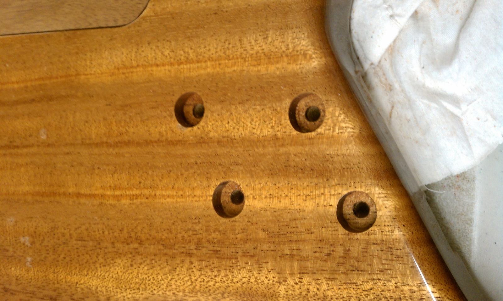
Looks like when I pulled the washer from the first hole (checking the fit), it chipped a tiny piece off... oh well, i'll drop fill it later..
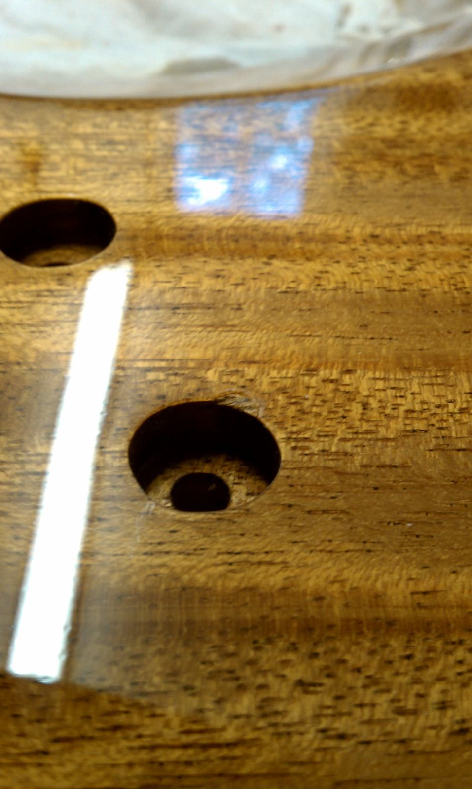
Had to make the neck screw hole, a little larger.
Taped the area off, so I could trace out the compression washers..
Sizing part done, the larger holes are the right size for the washer to stay in permanent ..
Looks like when I pulled the washer from the first hole (checking the fit), it chipped a tiny piece off... oh well, i'll drop fill it later..
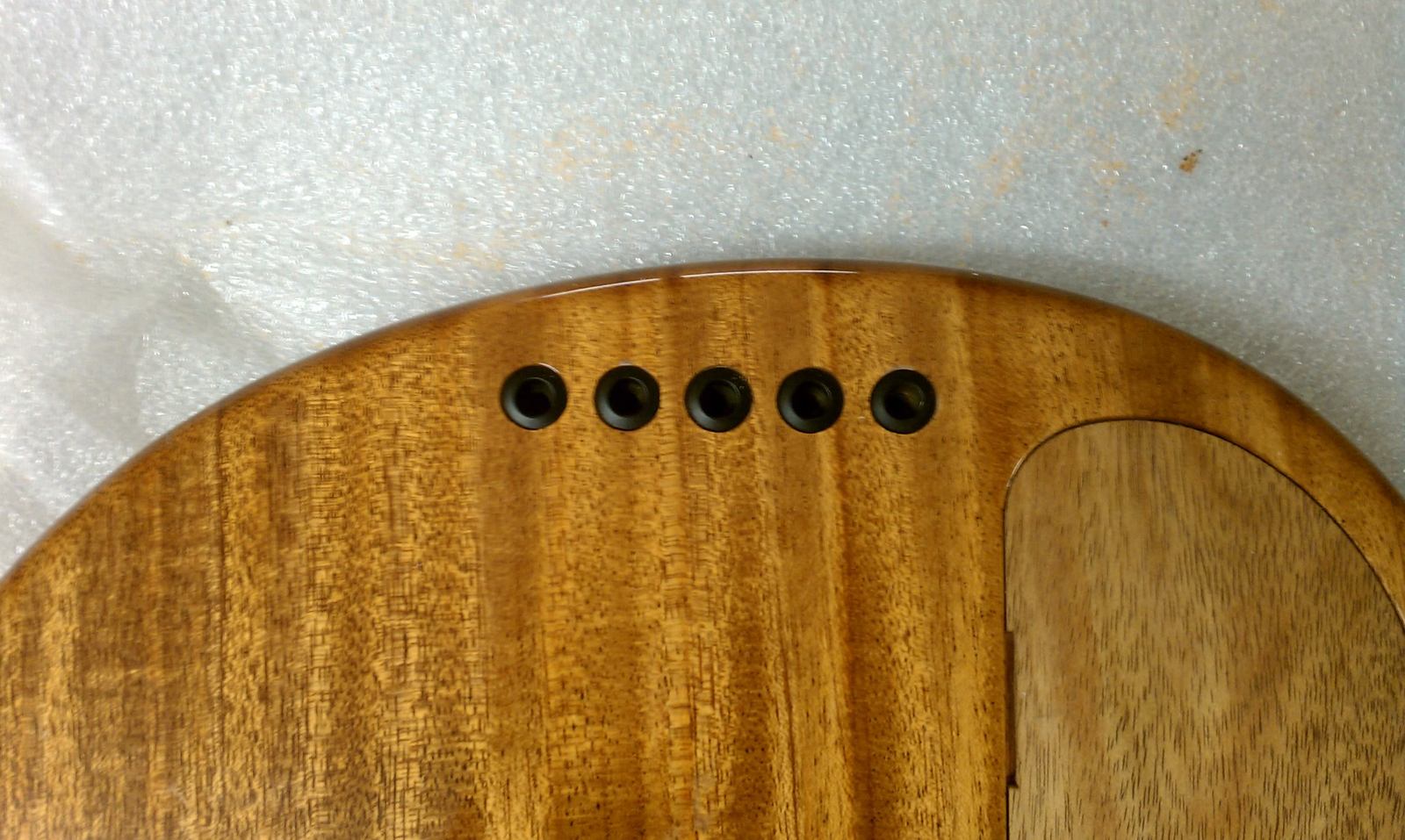
Turns out that the supplied string ferrules are slightly larger than than the warmoth holes, no problem though.
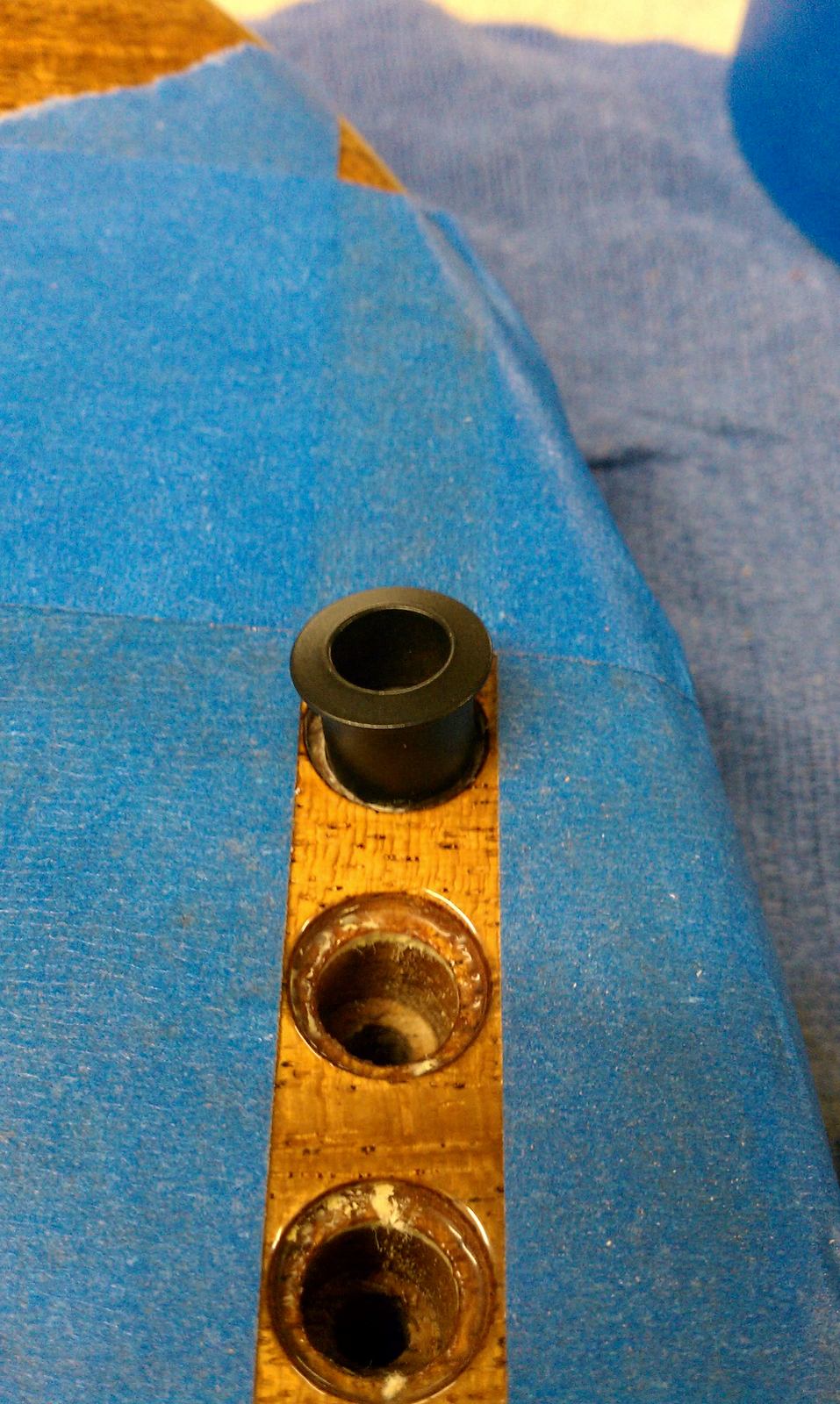
.....Gotta resize with the dremel
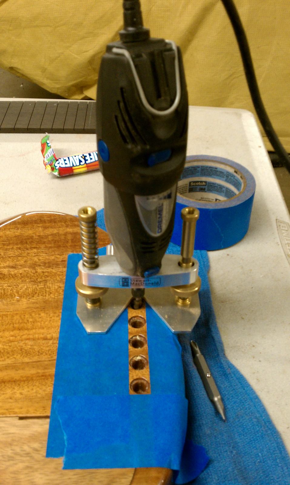
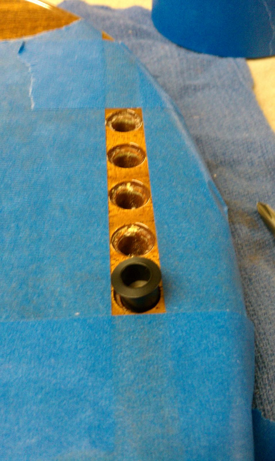
I'll also need to make the top part bigger too...
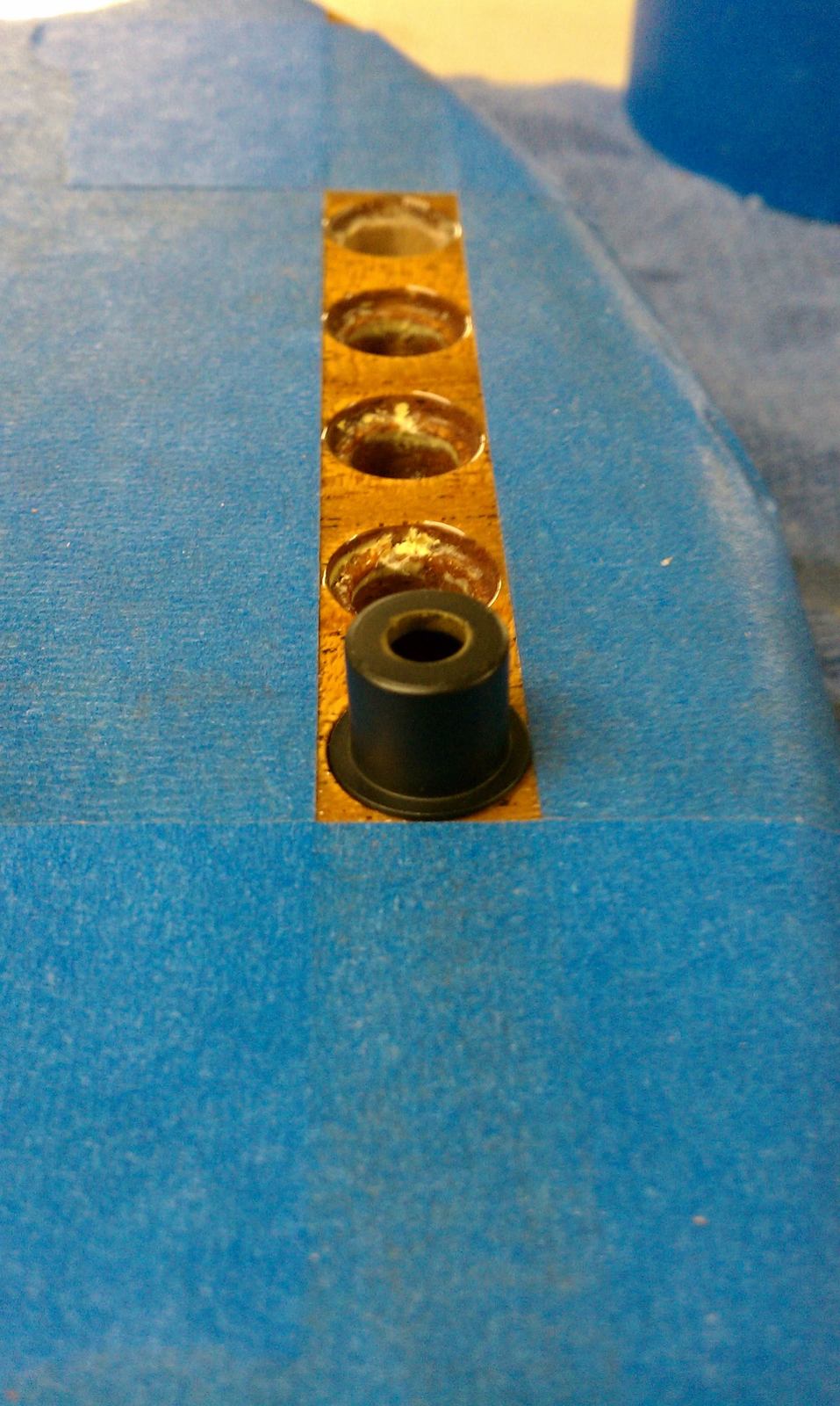
.....Gotta resize with the dremel
I'll also need to make the top part bigger too...
I told you nearly all of the holes on that body were small. lol
Thanks for doing the extra stuff, i appreciate it!
Thanks for doing the extra stuff, i appreciate it!
Now to fit them and Insert the ferrules....
Made a template for the correct diameter or the top side.
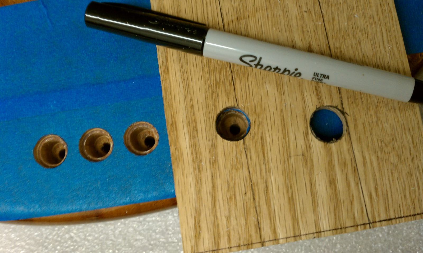
Used the dremel and then.......we're here?
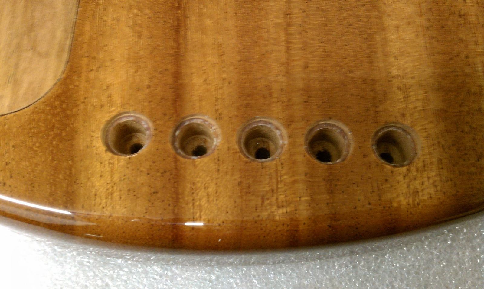
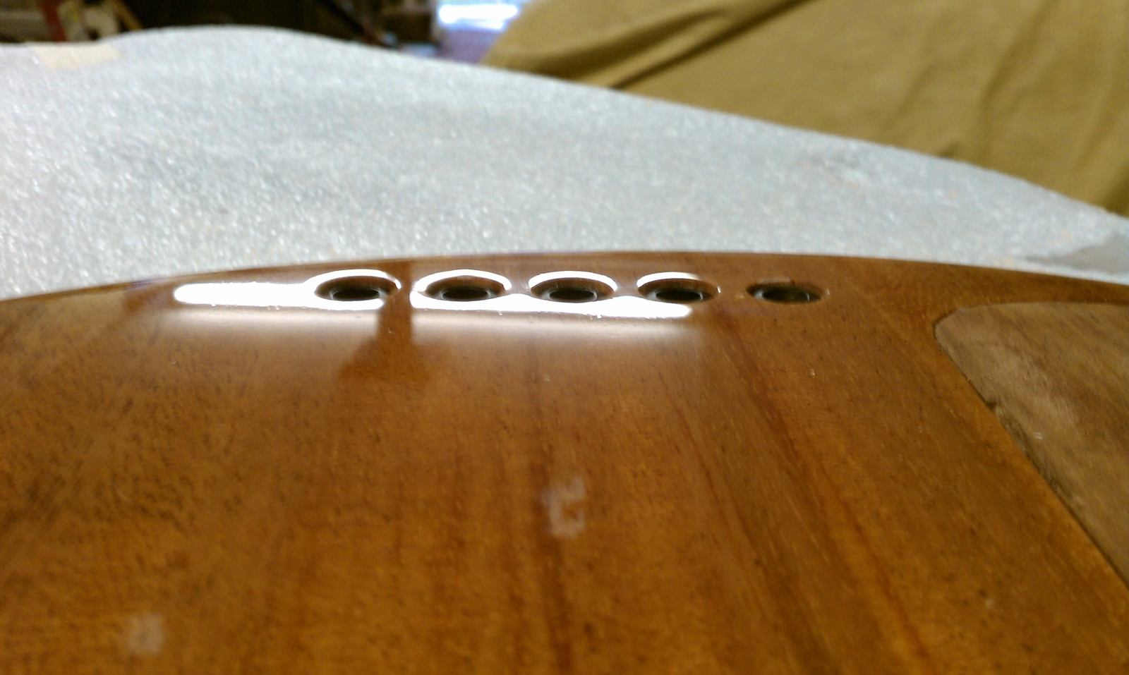
Well now they fit...
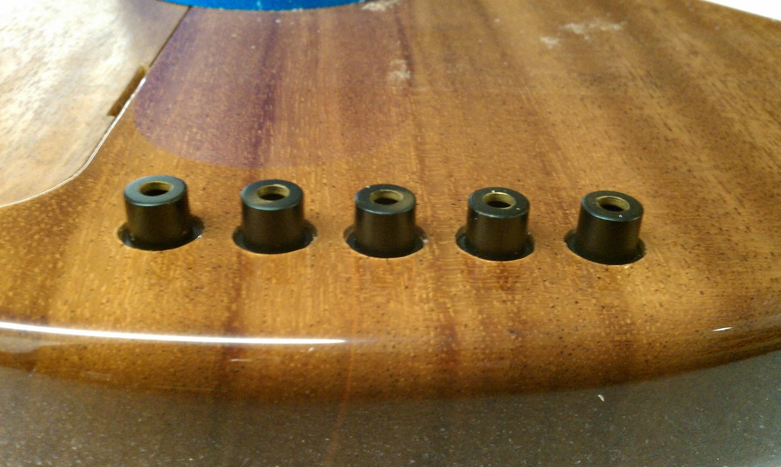
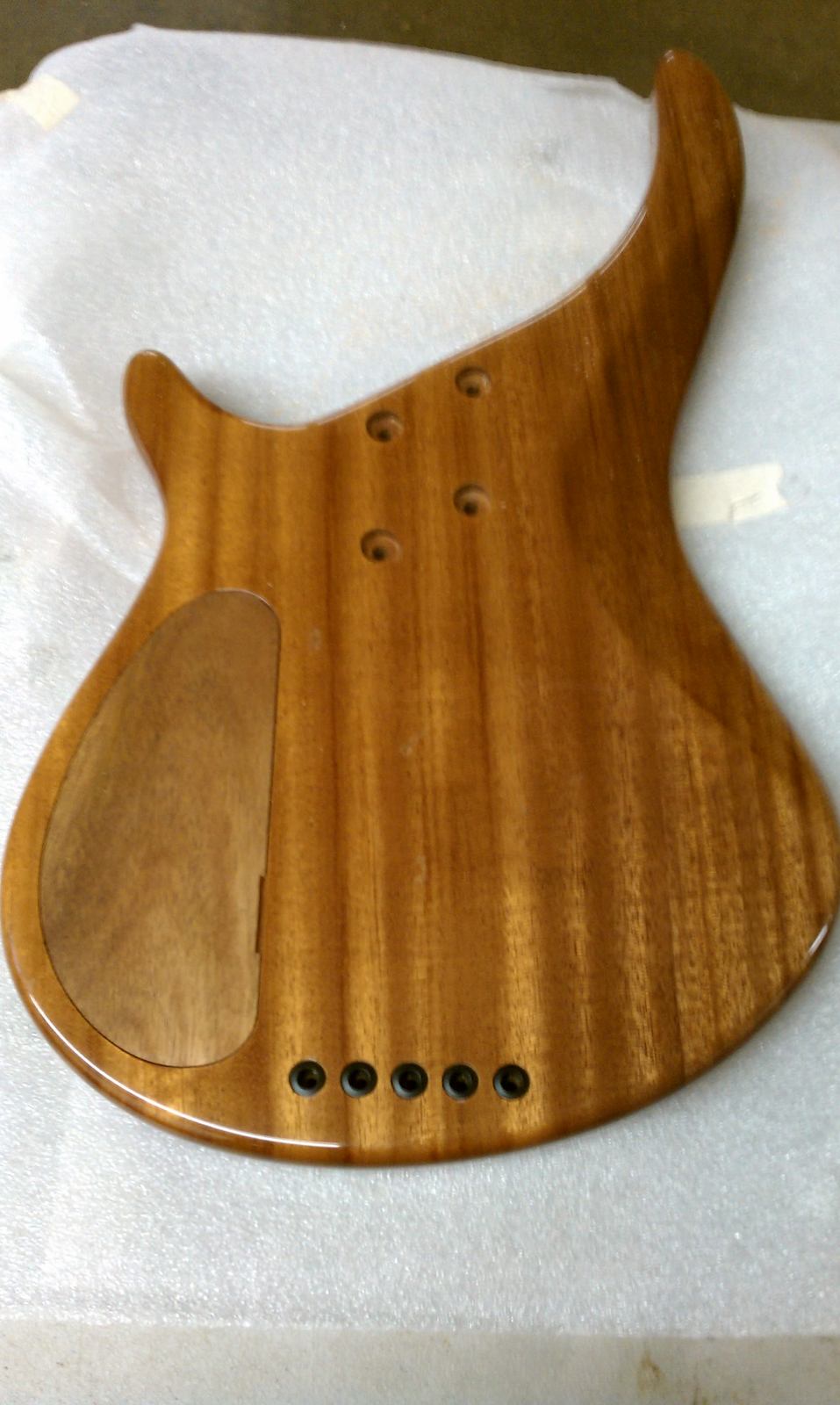
And now they're in..
Next up, headstock shape....
Made a template for the correct diameter or the top side.
Used the dremel and then.......we're here?
Well now they fit...
And now they're in..
Next up, headstock shape....


