• TalkBass has been independent since 1998. Add your voice.
    Create a free account to reply to discussions, view embedded media, and browse with fewer display ads.
    Join freeLog in
    Want zero display ads or expanded classifieds tools? Compare plans.

Roberto-Venn: The Dream Starts...

Hello all!!

Today was yet another productive day!

First, I started with the vertical strips. Here is a shot of kerfing, which has been cut out, leaving room for the vertical strips.
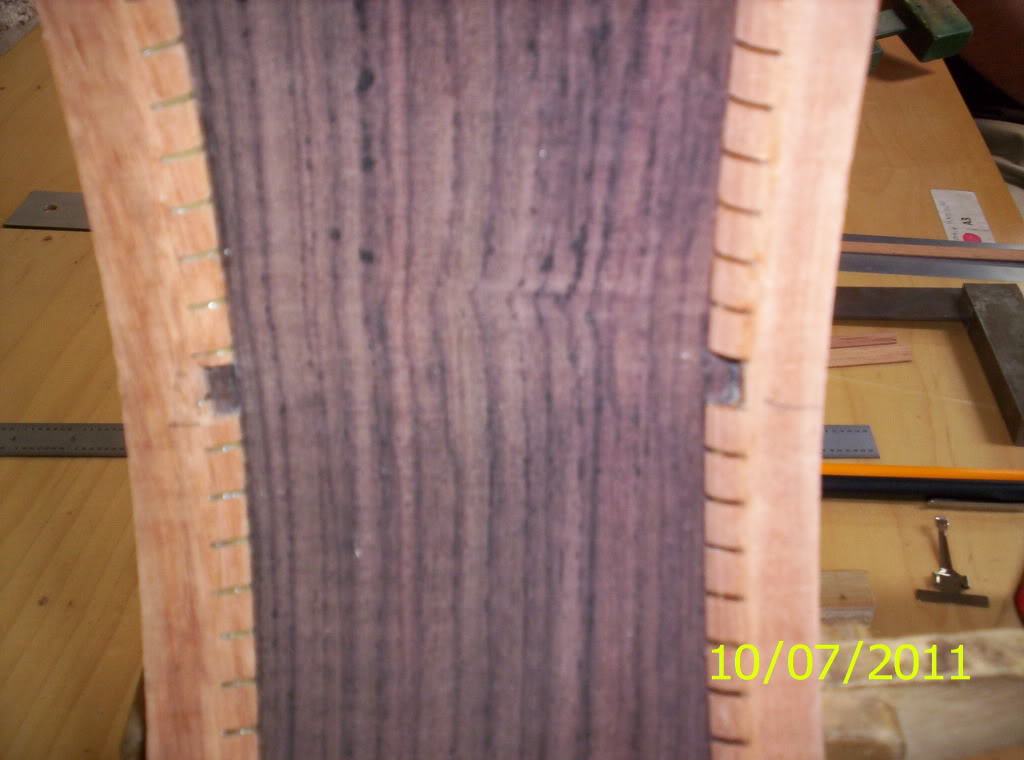
105_7496.jpg


And here, you can see the strips in place.
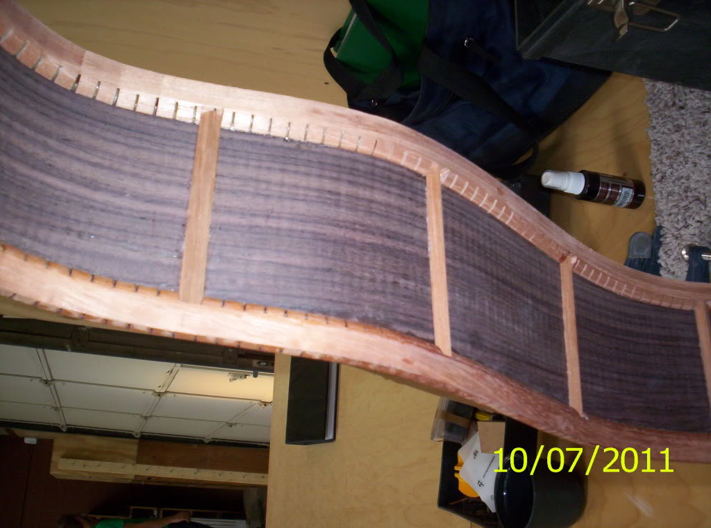
105_7494.jpg


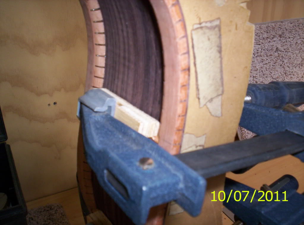
after a dry fit, I glue the strips, place a caul over the strips, and clamp them in place.
105_7495.jpg


But I try not to glue just one...

105_7498.jpg


and the end result...

105_7493.jpg

well, I like it!

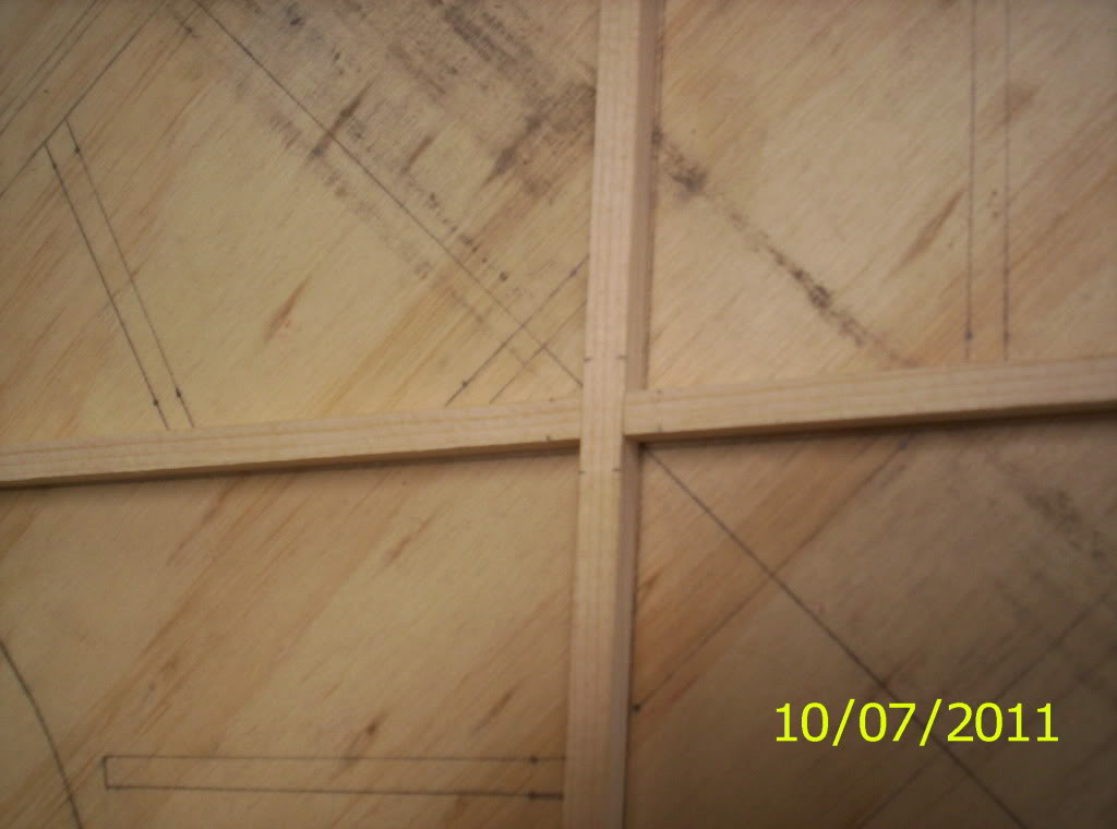
Next was on to the beloved "x-brace"
105_7502.jpg


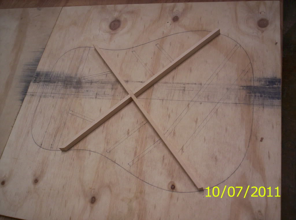
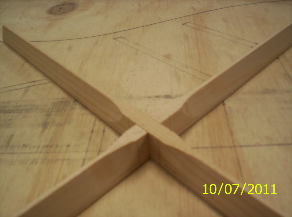
After a tight fit..the braces had to be cut to the shape of the mold (which is drawn out on my work board).
105_7499.jpg


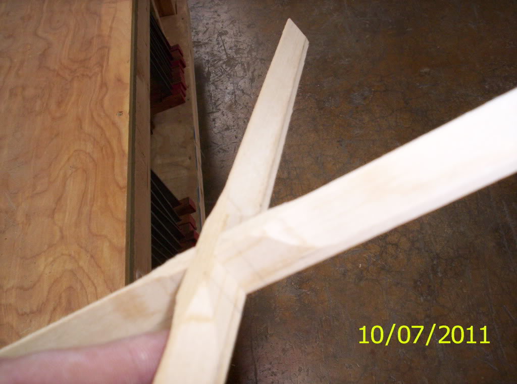
And then, it is thickness sanded using a specialized jig. John Reuter has offered to answer questions regarding making this jig, but, he said it involves lots of trig., which I really don't feel like learning. Any way, here are some shots of the tapered braces
105_7504.jpg


Now they are getting close to familiar...
105_7503.jpg


I will say that, when I took these pictures, I didn't have all of my sides even. I did go back and fix that. The taper now stops 1/4" from the joint lines, on all sides. I then continued by radiusing the braces to a 30' radius...which was tedious, but worth it!

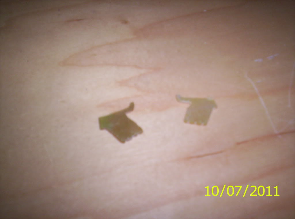
Next was a request from several people....
105_7507.jpg


I have a right-handed slapper's thumb!

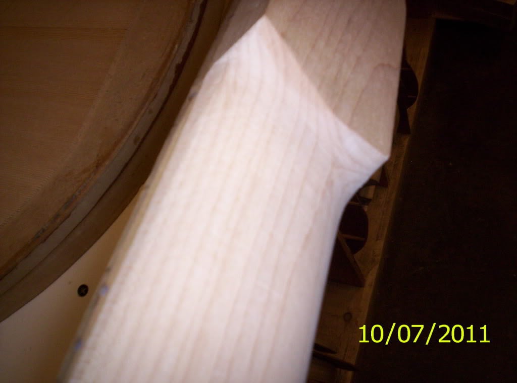
and finally, I took some sandpaper and sweetened the spot, right below the headstock and right above the heel, on the bass neck.
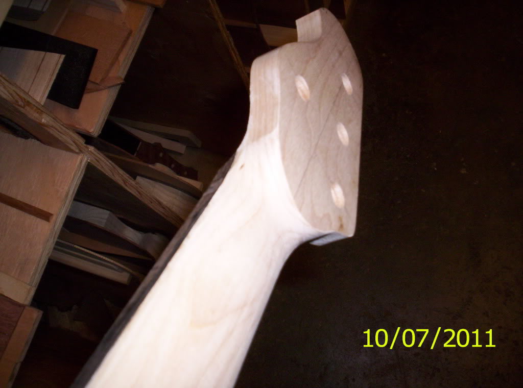
105_7509.jpg


105_7511.jpg


I did not take any away from the actual thickness of the neck, just from the spot separating the headstock from the neck. I did see something that I would like to ask Kris about, and you can see it in this picture. There is the line of the headstock, and then a semi-circle, which are two completely different shapes. I would like to see if he will let me streamline the shapes together, make it one shape. I would photoshop this, but I don't have the means.
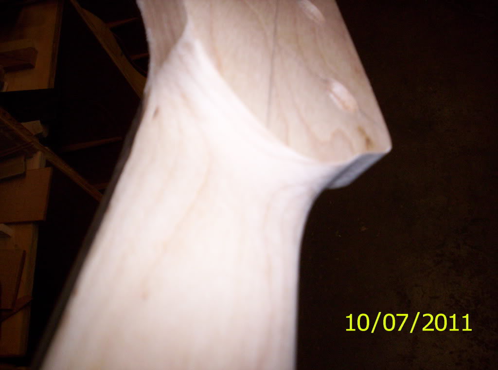
105_7510.jpg


One final proposition; I will be using a SD 3 band preamp, suited for the MM pickup. My questions are... 9v or 18 and, if 9v, should I route for battery box, or take up some real estate in this massive cavity?
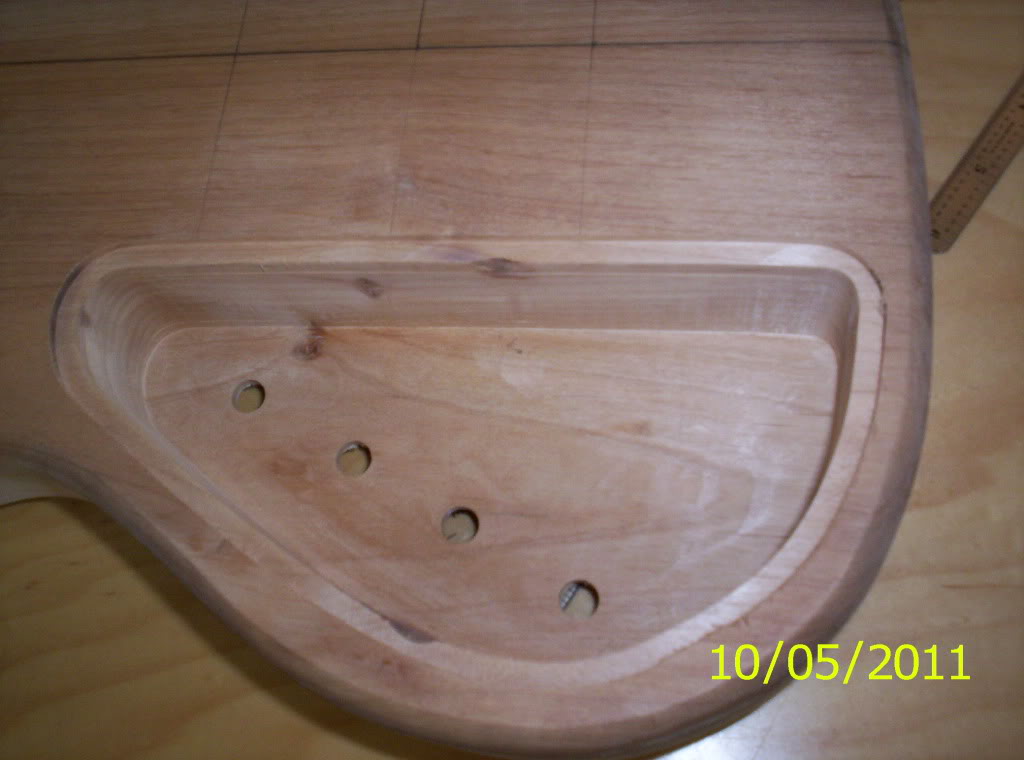
105_7470.jpg


Take your time, remember some of my previous posts about routers, use you own experience, and give me your honest opinion. I can't say that I will act one way or another, but, I am seeking advice. Thank you very much.

Well, the weekend is here! Have a safe one and.., see you guys Monday night!

As always, thanks for the comments, compliments, and thanks for watching!

Thumpin_P

 
That's a nice big cavity, and the Duncan preamp board is *tiny*, so I'd pop a battery clip or two in there, and save routing again. I'm sure you have room for two batteries in there, though the Duncan pre is fine at 9v.

Can you get some wee machine screws for the cover, so when you do need to change the battery you won't be stripping the wood. I have a Cort like that, and the battery compartments on my Roscoes, very handy.
 
Knucklehead, those are called "blurbs", and yes, you can do that, but that would require two individual templates. Doing it this way is a more streamlined approach. We will see if it works out for me. if not, I will glue some in. Thanks, BTW, I like the flipped thumb, too...
 
Maybe cut a few screwheads off and epoxy them into the holes, I saw a guy do that with a pickguard he wanted to be able to take on and off without drilling, but didn't want the holes showing.
 
It's certainly a possibility. I suppose if you used thick-ish plastic, or re-inforced it with sheet aluminum (in lieu of copper foil for shielding), it would be rigid enough to stand up to the weight of a battery.
 
Okay!

Another fairly productive day!

First, I didn't like the way the back of the bass headstock looked. The transition was simply unprofessional looking. I asked Kris ( lead electric instructor) if I could do some sanding, to smooth out the transition. He said "sure" so...,

105_7512.jpg


I like this better...

105_7515.jpg


I also realized that I did even more sanding after this photo...No, I didn't screw that up. Ha Ha!

I also sanded the transition between the round-over and the comfort carve..sorry, I forgot to get a photo. I will get one tomorrow. Needless to say, that turned out better than i thought it would.

A separate note, I have made my decision about the battery box. I am not really a gigging musician, so I won't need to constantly open the cover. I am not quitting or giving up, just being realistic. I have lots of work to do to really clean up all of my mistakes on the bass, so, adding another variable, which could end badly (not saying that it would, but that it could) doesn't make much sense. I am okay with this decision. I do appreciate all the help that I got over weekend. It did not go unnoticed.

Next, I needed to get the X-braces glued in. That was pretty good, but, right after all of the go-bars were in place, the brace shifted. I got off of my center line, just a little, and Matt Baker, another instructor, basically told me "it's fine". That's not exactly what he said, but we have a repoir, that wouldn't convey well over the internet.

Anyway, I also got the bridge plate made and glued in, this took several attempts to size. It took me five attempts, which would have really upset me before, but, because of the support of you guys in this forum, I realize now, that this small stuff. No big deal. So, Thanks!

With that being said, here is a pretty good picture...

105_7517.jpg


I also got the lower face braces tapered, and pretty much, ready for gluing. Here they are, in place, just not glued.

105_7516.jpg


I also made some progress with the soundhole braces and the finger braces. I thickness sanded all of them, they are identical in size and taper, so I figured that I would shape both of them at the same time. They ended up 1/4" x 1/4", which what they are supposed to be. I then started tapering them, using another jig. I sanded way too much off of the first stick, so i adjusted the sander and did the second one correctly. This just means that I have to redo one stick..again, no big deal.

The last thing on the agenda today, was a demo on using threaded inserts for the bolt-on necks. I can get more into this tomorrow, suffice it to say..., I have six holes in my neck pocket... It's a start!

105_7519.jpg


And..., yes, there aren't any holes in this picture. I will document everything tomorrow, step by step.

Tune in for more tomorrow and again, thanks for all you guys do!

Thumpin_P
 
Hello everybody!

WOW!!! I didn't realize just how productive today was, until I looked at all the photos.

First off, the neck joint. I could explain, but, I will save bandwidth for pictures...

First, aligning the neck to the body...

105_7520.jpg


I thought that I had a picture of just the starter holes, but I did not. The alignment was good with 1 13/32" on either side of the center line, so... on to drilling pilot hole in the neck!

105_7521.jpg


After that, drilling the holes for the inserts...

105_7525.jpg


and this picture might show the chamfer created with a countersink bit.

105_7524.jpg


with this,

105_7523.jpg


Next was cutting a recess in the back of the heel, for the heads of the bolts...

105_7526.jpg


The last drilling was to use a 17/64" to make a hole for the shaft of the bolts.

105_7527.jpg


we used these bolts...

105_7528.jpg


and here they are in place.

105_7529.jpg


Next, installing the inserts. Kris created an installation jig, to help with alignment. You thread the insert onto the bolt, set the bottom flat on the neck heel, and tighten down. This sure beats installing with a screwdriver...

105_7531.jpg


105_7532.jpg


Success!
Here are several shots of the installed inserts. After installation, we needed to wick CA glue in between the insert and the neck.

105_7533.jpg


After the glue dried, we used a tap, to clean any glue off of the interior threads, if any leaked out. from there, there was only one thing to do...

105_7537.jpg


105_7536.jpg


Thank you, Michael. Not a bad photographer...

I still look forward to lopping the excess off of the neck pocket on the treble side. That time is not far away...

The only other progress on the bass was to drill the wiring channel. I am glad that I only have one pickup.

105_7538.jpg


I did get pretty close to the edge of the pickup cavity, but, I think it will work.

105_7539.jpg


Moving on to the acoustic, most of the accomplished work was involving braces. At this point, though, there are a lot of braces.

I continued working on the lower face braces, tapering the edges. Here are a couple of shots. I don't know why I took two pictures...

105_7540.jpg


105_7541.jpg


After those get glued in tomorrow, the next will be a series of much smaller braces. the soundhole braces, and the finger braces. Here are all of them clustered together, my linkin' logs...

105_7542.jpg


I got the majority of the radiusing, shaping and fitting done with all the braces. I will finish up with the tapering of the soundhole braces in the morning, then, on to gluing! Here are a couple of shots. The first is the big picture...figuratively speaking...

105_7543.jpg


and a closeup of the soundhole braces. All are in place, but none are glued yet.

105_7544.jpg


After all the braces are glued in and cleaned up, then we start tapering and scalloping. Fun!

A whole lot of progress today, even though there were some small stumbling blocks. I did have to remake one stick of spruce, which became the finger braces. No big deal, I am learning very quickly to actually learn from the mistakes, and not get all frustrated. It is a great feeling.
Thanks to all of you for the support.

Tune in tomorrow, as I am sure there will still be progress...

Thanks for watching...

Thumpin_P
 

Latest posts