• TalkBass has been independent since 1998. Add your voice.
    Create a free account to reply to discussions, view embedded media, and browse with fewer display ads.
    Join freeLog in
    Want zero display ads or expanded classifieds tools? Compare plans.

Spækerbœx: 27.2Hz High-pass filter

So I've still got this thing laying around. Lost interest in it a while back as I moved on to other projects. Got an idea of what to do with it.

I built a single opamp buffer recently, and had the idea to use the circuit and add the second half of dual opamp to give this thing a buffer, as some recommended. It will only take a few changes to the original board, so this is will be cake.

Since I clearly suck at engineering these things, would anybody care to validate this?
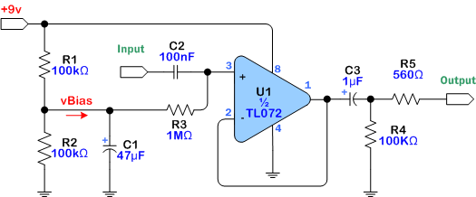

^^adding the second half^^
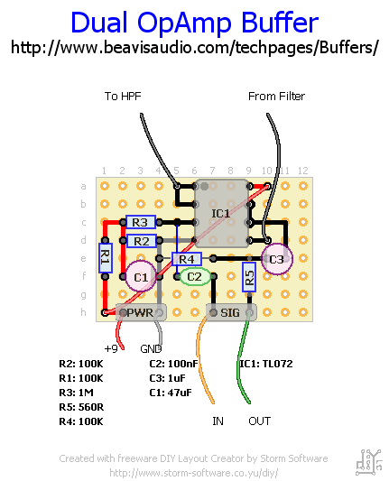
bKb9Wr9.gif

Pin: 5, input
Pin: 6/7, bridged output, right?
 
The filter was already inherently a buffer - not sure you're adding anything to it except some extra noise.

In response, this is the whole reason for this mod:

From my quick calculations it looks like the input impedance at 1kHz is max 68k. It may work if you use the unit in the send/return loop but I wouldn't use it connected to a bass.

The whole point is to defeat the low input impedance by adding a buffer at the beginning.
 
I just read thru the thread and I am a bit confused.

Your filter schematic in the first post shows positive and negative 15V supplies. Your pictures of your build show a two conductor power jack… how are you getting positive AND negative voltage? Did you build something different than the schematic you have posted?

-Frank
 
What's not pictured is a rail splitter section where you split a unipolar (e.g. 9V/GND) power supply into a bipolar (+4.5V/virtual GND/-4.5V) power supply. This can be done either by making a passive voltage divider or (much better) using a rail-splitting IC.

Also, re-read the first post - +15V/-15V would be way too much.
 
What's not pictured is a rail splitter section where you split a unipolar (e.g. 9V/GND) power supply into a bipolar (+4.5V/virtual GND/-4.5V) power supply. This can be done either by making a passive voltage divider or (much better) using a rail-splitting IC.

Also, re-read the first post - +15V/-15V would be way too much.

I am still not seeing or reading where he is using a rail splitter for a virtual ground.

Also, +/-15V supplies would not be too much for that opamp.

-Frank
 
I just read thru the thread and I am a bit confused.

Your filter schematic in the first post shows positive and negative 15V supplies. Your pictures of your build show a two conductor power jack… how are you getting positive AND negative voltage? Did you build something different than the schematic you have posted?

-Frank

What's not pictured is a rail splitter section where you split a unipolar (e.g. 9V/GND) power supply into a bipolar (+4.5V/virtual GND/-4.5V) power supply. This can be done either by making a passive voltage divider or (much better) using a rail-splitting IC.

Also, re-read the first post - +15V/-15V would be way too much.

I am still not seeing or reading where he is using a rail splitter for a virtual ground.

Also, +/-15V supplies would not be too much for that opamp.

-Frank

I'll concede that my original drawings were a bit goofy, as I didn't utilize standard terminology.

It should be +V and ground, like you'd use with a wall wart or battery. I'll update that if my request is approved.
 
Thanks. Where are you getting +15v and -15V from? Your build picture shows a 2 conductor power jack.

-Frank

I run my pedals with 9V or 12V power supplies, just standard stuff DC jack stuff. It's not +/-15V. So yeah, I deviate a bit. From my previous readings on TLXXX datasheets, they're tolerant to those voltages, but I don't necessarily use them.
 
I run my pedals with 9V or 12V power supplies, just standard stuff DC jack stuff. It's not +/-15V. So yeah, I deviate a bit. From my previous readings on TLXXX datasheets, they're tolerant to those voltages, but I don't necessarily use them.

This is where your problems are. It is perfectly OK to convert a dual-rail powered circuit to a single ended supply, but you need to bias the active components (in this case, opamps) to operate with the single ended supply. But, when you “deviate a bit” and ask for help you need to include ALL of the circuit and information.

I am assuming that you connected the -15V connections to ground. When you do that, the opamp has to be biased somewhere between the positive supply voltage and ground. You can not just modify the circuit by removing the negative supply and expect it to work properly. This is why you are hearing noise and distortion that you posted about on the first page of this thread.

Here is a very simple general rule of thumb for opamps:

If the circuit is operated from a single supply voltage, then the output of each opamp should have a DC voltage of approx half of the supply voltage to ground for maximum headroom.

If the opamp is powered by split-rail power (+V AND –V) then the outputs of the opamp(s) should have a DC voltage somewhere near the halfway point of the + and – supplies.

Examples: +15V and -15V supplies = opamp output biased to 0V (ground)
+15V and -9V supplies = opamp output biased to approx 3V

-Frank
 
His filter circuit is nearly 100% there already. It will also be noise/distortion free when he makes a couple of modifications.

To make your filter operate properly with the negative supply grounded, you will need to apply a Vbias to the grounded ends of R3 and R6 on the above filter schematic.

Use the Vbias circuit from the opamp buffer circuit in post #41 (R1 R2 and C1). Then lift the grounded ends of the resistors of R3 and R6 in the filter schematic in post #53 and connect them to the Vbias divider.

Then measure the DC voltage of each opamp output to ground for one half of the supply voltage.

-Frank