• TalkBass has been independent since 1998. Add your voice.
    Create a free account to reply to discussions, view embedded media, and browse with fewer display ads.
    Join freeLog in
    Want zero display ads or expanded classifieds tools? Compare plans.

Spækerbœx: 27.2Hz High-pass filter

Apr 5, 2011
1,287
630
CO
Updated to Revision 1.1, to include C10.

Caught a thread a while back about the [sfx] Thumpinator. Seemed like a great always-on add to an effects chain, but I can't afford it. Did some research and put together a high-pass filter that cuts off anything below approximately 27Hz, protecting the speaker and running the amp more efficiently. Look into it if you want.

Seems to work as advertised. I can't determine if it's adding to or enhancing the buzz from the Jazz that I had nearby, or perhaps buffering the signal to pass through the next 15' of cable to the amp more betterer; try a different bass later.

Accidentally shorted the signal to the -15VDC with just a hairline of extra solder, burnt out the IC. Luckily they cost a quarter and I had ordered ten of them. :crying:

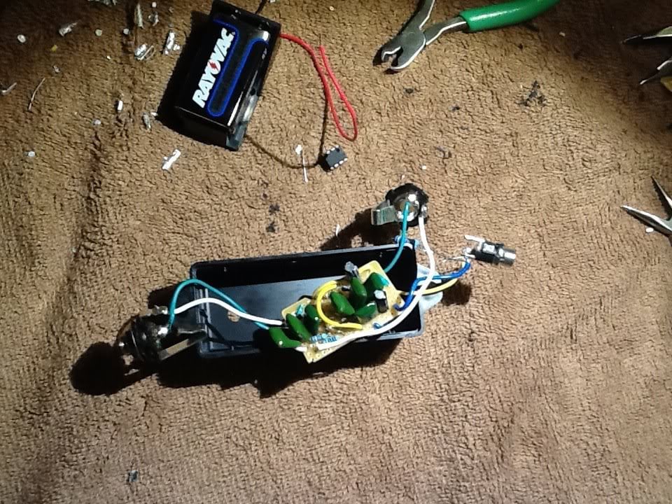
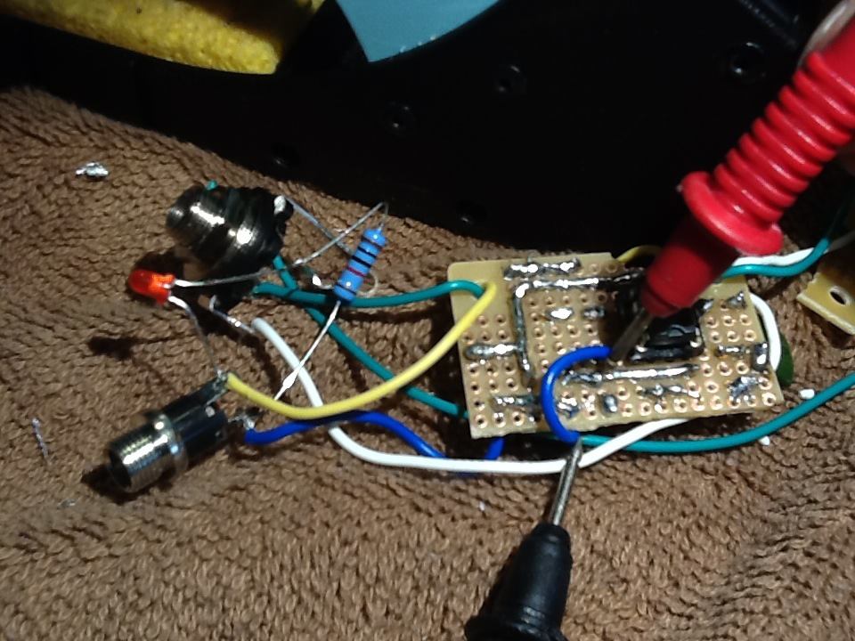
Nearly did a mirror-image and installed the IC backwards, that's why it's mounted on the underside. Oops.

It's sorta ugly, but it's the first thing I've built that wasn't an Altoids box stuff with LEDs or an FX loop pedal. I could have made the schematics more eye-friendly, but I did them nearly identical to how I arranged everything on the board.

Feel free to critique and suggest improvements for when I build a few of these for friends.
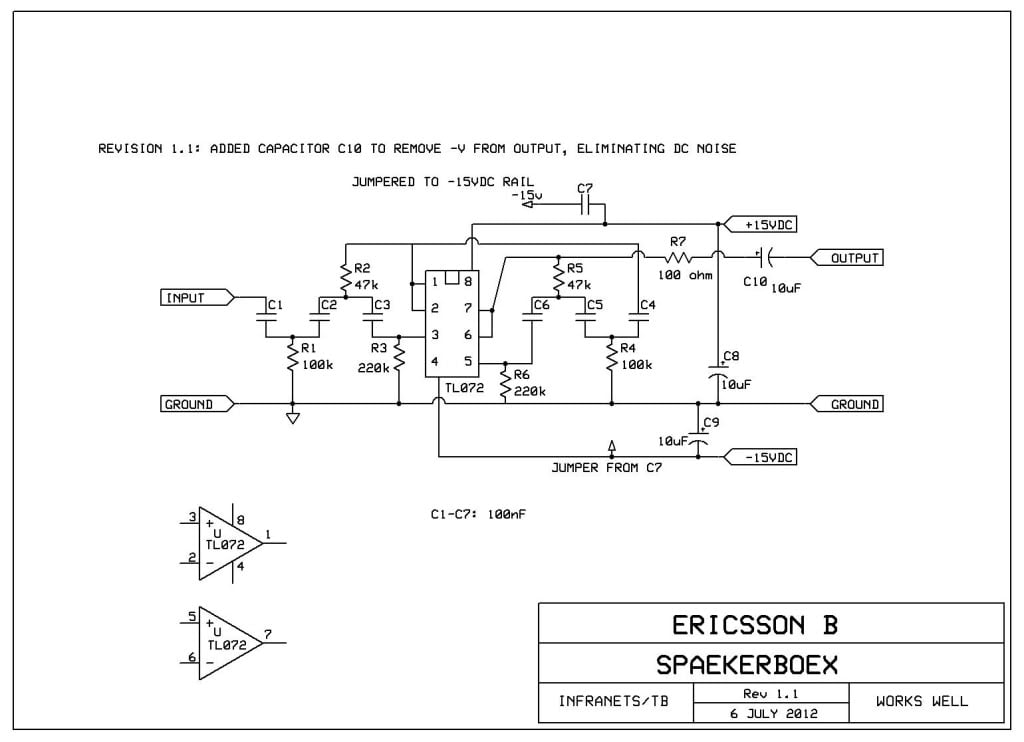
SPAEKERBOEX11.jpg

Do not use a ~30V power supply. Use a 15V at the most. +/-15V is erroneous, but not worth the effort to update the image.
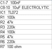
SPEAKERBOEXXLIST11.jpg

SpaekerboexTopside.jpg

SpaekerboexUnderside.jpg


Recommend these in case you jack up an IC:
8_pin_DIP_IC_Sockets_Adaptor_Solder_Type_Socket_2.jpg
 
Put it in my 5er ESP that has two soapbars; noise may be inherent to this IC. May try a different one. Seems to boost the signal a bit, too.

My power supply is pushing 13.8VDC, rather than 15. Perhaps that affects noise and signal. Any people, cyborgs or droids around here know about this stuff?

Should probably take the amp, bass and filter to work and use the o-scope there to mark specific levels, rather than go by ear.
 
This, along with the exchange rate, is why the [sfx] unit costs what it does. It has zero noise, zero hum, does not amplify them; it is built tight and proper; it runs on 9v.

Edit: (deleted some grumpy language)
On re-reading your post I may have reacted too strongly; it's just that I've seen a few too many posts here saying the Thump should cost much less than it does since a filter is so easy to make.
 
Put it in my 5er ESP that has two soapbars; noise may be inherent to this IC. May try a different one. Seems to boost the signal a bit, too.

My power supply is pushing 13.8VDC, rather than 15. Perhaps that affects noise and signal. Any people, cyborgs or droids around here know about this stuff?

Should probably take the amp, bass and filter to work and use the o-scope there to mark specific levels, rather than go by ear.

It isn't quite clear, how you achieve the +/- 15v and a clean ground from a 15vDC supply. I see tree pins for power, but the DC-jack only has two. If you are running a single-ended supply, you need to take good care of, how you get a clean virtual ground (on some schematics noted vb), This might very well be source to the hum, and perhaps some of the noise too.
Another ting to notice, is that you have put it in an uninsulated box... Noise and hum could be picked up from the universe and the mains in your house.

This, along with the exchange rate, is why the [sfx] unit costs what it does. It has zero noise, zero hum, does not amplify them; it is built tight and proper; it runs on 9v.

Edit: (deleted some grumpy language)
On re-reading your post I may have reacted too strongly; it's just that I've seen a few too many posts here saying the Thump should cost much less than it does since a filter is so easy to make.

I too am thinking a bit about slamming together one of these. Not to disrespect [sfx] in any way, or to say that their products are too expensive - I know how prices are in Europe - but if I can get something similar, cheaper, plus I get an afternoon of fun designing it and another one, just as fun, building it; there really isn't much of a choice. :)
 
As Skrogh said, you could try using an aluminium enclosure just to see if part of the hum disappears.
For me at least, it's usually worth trying to DIY something even if your end product is slightly inferior to the commercial product and you spent more money if you factor in your time.

Nice caps, do they add mojo? ;)
 
As Skrogh said, you could try using an aluminium enclosure just to see if part of the hum disappears.
For me at least, it's usually worth trying to DIY something even if your end product is slightly inferior to the commercial product and you spent more money if you factor in your time.

Nice caps, do they add mojo? ;)

Be aware, if you use a metal-box, that the DC jack doesn't short out against it.
 
Interesting. Would love to see a 9v version of this.

I'll plug in a 9V and let you know. Should work. TI says:
Total Supply Voltage (Min) (+5V=5, +/-5V=10) 7
Total Supply Voltage (Max) (+5V=5, +/-5V=10) 36


This, along with the exchange rate, is why the [sfx] unit costs what it does. It has zero noise, zero hum, does not amplify them; it is built tight and proper; it runs on 9v.

Edit: (deleted some grumpy language)
On re-reading your post I may have reacted too strongly; it's just that I've seen a few too many posts here saying the Thump should cost much less than it does since a filter is so easy to make.
I too am thinking a bit about slamming together one of these. Not to disrespect [sfx] in any way, or to say that their products are too expensive - I know how prices are in Europe - but if I can get something similar, cheaper, plus I get an afternoon of fun designing it and another one, just as fun, building it; there really isn't much of a choice. :)

Wasn't intending to knock on [sfx] at all, just that I can't afford it. You can't complain an unmatched high quality product. The idea was bassically to get something that does the job, and get the experience of making it myself.

This is the first active circuit that I've ever put together, so I'm pretty happy with it so far. :bassist:

As Skrogh said, you could try using an aluminium enclosure just to see if part of the hum disappears.
For me at least, it's usually worth trying to DIY something even if your end product is slightly inferior to the commercial product and you spent more money if you factor in your time.

Nice caps, do they add mojo? ;)

Exactly! In a morning-after review, the noise is only really noticeable when run at full volume. You know, master set to full and gain set at noon -- the kind that blows up the entire downstairs of my house, which is what this thing is supposed to protect my amp from. So far, the positive outweighs the negative exponentially. Can not hear it when anything else in the room is making noise.

When I opened and closed the circuit on that red LED that's on the power supply, I noticed an apparent increase in noise with it closed/on. Pretty much going to change out two carbon filters (also a decent chance that I got them too hot during the build, thus making them noisier) that made it on to the circuit for some metal films, then find a power supply that's not one-I-just-found-in-the-garage-the-other-day.

I dig the caps and how they're arranged -- probably could have spaced them out a little more, but then I'd have to put them on a bigger circuit!

Be aware, if you use a metal-box, that the DC jack doesn't short out against it.

Roger that. Center-positive!

Now, if someone who owns the [sfx] model has one an coincidentally opens it and takes pictures and sends them to me... :ninja:
 
Hi EricssonB

The diagram uses the IC layout instead of the usual op-amp triangular symbols and I find difficult following it. I’ll try to re-draw it later.

There is something I can’t understand though. The TL072 is a dual op-amp (i.e. 2 op-amps in the same IC). The symbol in the lower left side of your drawing shows a single op-amp.

With a clearer diagram it would be easier for me to give you some suggestions but it looks like the input impedance is very low (100k // 220k). You may want to address that. It might also be useful to add a capacitor to the output, just in case some DC is present.

Regarding the photos of the inside of the micro-Thumpinator, I run out of micro-Thumpinators and to take a photo I’d have to take my micro-Thumpinator out of the pedalboard. Perhaps someone else can give you a hand. Having said that, I am not sure it would help you to improve your design. From a first look to your schematic I don’t see many similarities but I may be wrong.
 
Hi EricssonB

The diagram uses the IC layout instead of the usual op-amp triangular symbols and I find difficult following it. I’ll try to re-draw it later.

There is something I can’t understand though. The TL072 is a dual op-amp (i.e. 2 op-amps in the same IC). The symbol in the lower left side of your drawing shows a single op-amp.

With a clearer diagram it would be easier for me to give you some suggestions but it looks like the input impedance is very low (100k // 220k // 47k). You may want to address that. It might also be useful to add a capacitor to the output, just in case some DC is present.

Regarding the photos of the inside of the micro-Thumpinator, I run out of micro-Thumpinators and to take a photo I’d have to take my micro-Thumpinator out of the pedalboard. Perhaps someone else can give you a hand. Having said that, I am not sure it would help you to improve your design. From a first look to your schematic I don’t see many similarities but I may be wrong.

Hey there, Silent Fly! Probably can't find a better person to talk to about this. :humbled:

Just got back from doing an on/off comparison using my loop pedal. Pretty happy it it. Gonna rate this project as a success: 95%, with possibility to make it to 99%.

Good point on the funky schematic. Since I was documenting it with the intent of showing signal flow, I threw the 1-8 rectangle in there. I simply left the single op-amp symbol over there so that when I exported the parts list, the TL072 shows up; could probably do well by showing the correct part.

What would you suggest about changing the impedance? The capacitor for DC? Would these two things be related to the ever-so-faint signal that this puts on when its power is removed?

Edit: None of the other rumble filter schematics that I've looked around at have a resistor before the output; is R7 unnecessary and just adding noise?
 
Gonna rate this project as a success: 95%, with possibility to make it to 99%.

I am glad to hear that you're happy with the result. :bassist:

What would you suggest about changing the impedance?
From my quick calculations it looks like the input impedance at 1kHz is max 68k. It may work if you use the unit in the send/return loop but I wouldn't use it connected to a bass.

To increase the input impedance you have two choices: redesign the filter or add a buffer.

The capacitor for DC?
You need stop the DC present on the out of the op-amp to go out of the unit.

Would these two things be related to the ever-so-faint signal that this puts on when its power is removed?

I doubt it. If you re-draw the diagram with standard symbols, you'll see where the signal comes from. :eek:

Edit: None of the other rumble filter schematics that I've looked around at have a resistor before the output; is R7 unnecessary and just adding noise?
R7 is not part of the filter. In practical terms a 100R resistor adds zero noise. The circuit would work without R7 but it is more robust with R7.

I hope the above helps.
 
I am glad to hear that you're happy with the result. :bassist:


From my quick calculations it looks like the input impedance at 1kHz is max 68k. It may work if you use the unit in the send/return loop but I wouldn't use it connected to a bass.

To increase the input impedance you have two choices: redesign the filter or add a buffer.


You need stop the DC present on the out of the op-amp to go out of the unit.


I doubt it. If you re-draw the diagram with standard symbols, you'll see where the signal comes from. :eek:


R7 is not part of the filter. In practical terms a 100R resistor adds zero noise. The circuit would work without R7 but it is more robust with R7.

I hope the above helps.

Thanks. Luckily for me, I've got an effects loop on my amp. Never needed it. I'll try it next time I plug in.

Next step is to look into the capacitor for the DC.

I truly appreciate your input. I'll stop back in when I make these changes. :cool:
 
This is cool stuff and could help out a lot of speakers with amps that either don't have built in filters (SWR, some pre/power rigs), or not enough filtering for lower excursion speakers.

I don't have the chops to help you with the electronics bit, but, Tber fdeck works on similair things. He has a free design out there for an hpf for upright peizo pickups and is working on another cost, but affordable, design that would work in an effects loop. I take it this design does the filtering before the signal hits the amp?

I would say you can get away with moving your filter frequency a bit north, like 35-40hz. That would offer even more protection and in most bass rigs, you couldn't hear a difference with the filter in there. They just don't have the output down there, regardless of whatever rediculous claims some of the ad pages say. Live sound concert subwoofers are usually highpassed around 40hz and we all know how that sounds. Most bass rigs aside from some of the 30xxLF designs just don't have it down there. Your filter would do a nice job of stopping cones from flapping about killing themselves teying to make sound they can't make as well as using the amp power up where it can be better used.

Cool stuff.
 
Seemed adequate. I'll pick up some 74s and do a hot swap. Glad I used that DIP socket.

TL072 and TL074 are the same op-amp, the 074 is a bigger chip and houses four op-amps, instead of 2 (you can't fit a 074 in a dip8 socket.). The 072 is a perfectly fine op-amp for must applications. As long as you don't hit the rails, it's fine.

I'm still a bit confused about, how you got a +/-15V supply as the schematic says, from a 15VDC supply (13.5V, but that doesn't matter)
 
TL072 and TL074 are the same op-amp, the 074 is a bigger chip and houses four op-amps, instead of 2 (you can't fit a 074 in a dip8 socket.). The 072 is a perfectly fine op-amp for must applications. As long as you don't hit the rails, it's fine.

I'm still a bit confused about, how you got a +/-15V supply as the schematic says, from a 15VDC supply (13.5V, but that doesn't matter)

Just what I pulled from the Internet. Since the IC will run a fairly decent range of voltages, I'll change the schematic accordingly.
 
You need stop the DC present on the out of the op-amp to go out of the unit.

Checked the voltage this morning. There's definitely some current flowing between the output and -V.

Guess that'd explain C1, the 10uF capacitor on the output of this preamp that I'm going to copy: (it's a link, if you want to click on it)
parts.jpg

Meanwhile, there community college down the street offers "EIC 105 BASICS OF AC & DC ELECTRICITY" so I could stop bugging people with these things that I should know.