
For those who are wondering and didn't ask via PM, the bonus headphone amp pcb I included is the one from
http://www.talkbass.com/forum/showthread.php?t=641917.
http://www.talkbass.com/forum/showthread.php?t=641917.

TalkBass has been independent since 1998. Add your voice.
Create a free account to reply to discussions, view embedded media, and browse with fewer display ads.
Join free Log in
Want zero display ads or expanded classifieds tools? Compare plans.

Now THAT is beautiful work!
You say that you are planning on using cloth covered wire? Where do you find it small enough to fit through the strain relief holes?
Now THAT is beautiful work!
You say that you are planning on using cloth covered wire? Where do you find it small enough to fit through the strain relief holes?
I thought there would be enough room to drill out the holes to 7/64th to just pass the inner insulation of the cloth wire through, but there just isn't enough material to drill them out that far on the one side..
Just opened up the board file and there should be enough clearance to open them up to 0.1" (just under 7/64). Is that too tight?
Is this the hole/pad pair that's giving problems?

That is part of it, but I started two adjacent holes at 7/64 (just went past the bevel on the bit) and the two holes overlapped.
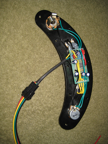
Here it is with the quick disconnect and everything ready to go:
That is part of it, but I started two adjacent holes at 7/64 (just went past the bevel on the bit) and the two holes overlapped.
Here it is with the quick disconnect and everything ready to go:
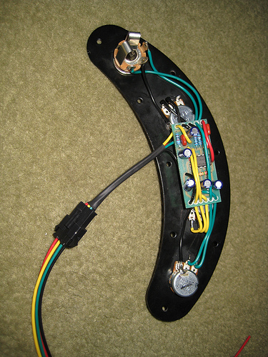

That'll be a stereo jack. The circuit is only complete when a jack is installed. This connects the "ring and sleeve" connections of the stereo socket, which completes the circuit that powers the preamp.
But I'll admit I'm not entirely sure of how the "regular" EB MM jack with the 4 connectors works.
Got paid, so going to get the rest of the bits ordered up today

Wonder why they went with that black boxed socket as opposed to a stereo open one.

So, initially they just used a standard mono jack socket?
Wonder why they went with that black boxed socket as opposed to a stereo open one.
Also, tantalum or aluminum electrolytic for the polarized caps?
It has PC-mount terminals, which might be a reason. They'd have the option of PC or wiring to the jack.
Either that, or it was the one readily available, at the right price, at the time they switched.
tantalum or electrolytic is a matter of personal preference. I think either one will sound great in the circuit. I went went electrolytics because Leo Fender liked them. I would try both and choose the best sounding, the caps are pretty cheap. I just learned ceramics aren't really that bad after all if they stay in spec. they have their own tone character and their slightly microphonic effect gives slight feedback that I like
Wasn't there an original problem with the standard type jack? Something about draining the battery I recall was the reason they went to another type jack.
Oh, and where did you get the wire? I'm assuming it's stranded wire?
I think the second one I build is going into my Warmoth P, I just need to find the right type of rebuildable stacked pots that will let me swap discs to have a treble/bass stack.
Ah, good shout.
I was just wondering what differences there were really. I've always used the electrolytics in circuits, just seeing a few people here using tants and some of the original ones used tants too.
And aye, the only problem I have with ceramics is the huge tolerance range you get with the cheaper ones!
The 1977 Stingray I once owned had ceramic caps and the tone was incredible