• TalkBass has been independent since 1998. Add your voice.
    Create a free account to reply to discussions, view embedded media, and browse with fewer display ads.
    Join freeLog in
    Want zero display ads or expanded classifieds tools? Compare plans.

The Hossenfeffer II Build

Fantastic!

When I put a new plastic/bone nut on one of my basses, I just filed the grooves to the right depth and did not file any off of the top (lazy). The strings sit within canyons and I have had no issues. However, I can see how they may bind in the groove during string removal and cause the nut to crack.
 
  • Like
Reactions: Gilmourisgod
Details........
pc7ww6p.jpg

XgeNO6e.jpg
 
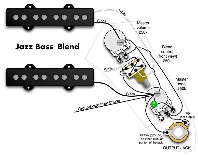
I'm using this wiring diagram for a Master Volume/Blend/Master Tone setup. I used the Bourns Blend pot, which has a minimal exterior metal case. The diagram shows what looks like a solder blob and ground wire on the side of the blend pot, anybody do this on one of these little pots? pretty nervous about trashing it with too much heat. It doesn't look like the case is tinned at all, so I guess I'll have to sand a bright spot and hope it takes solder? Any other way to wire that?
S6nYNBc.jpg


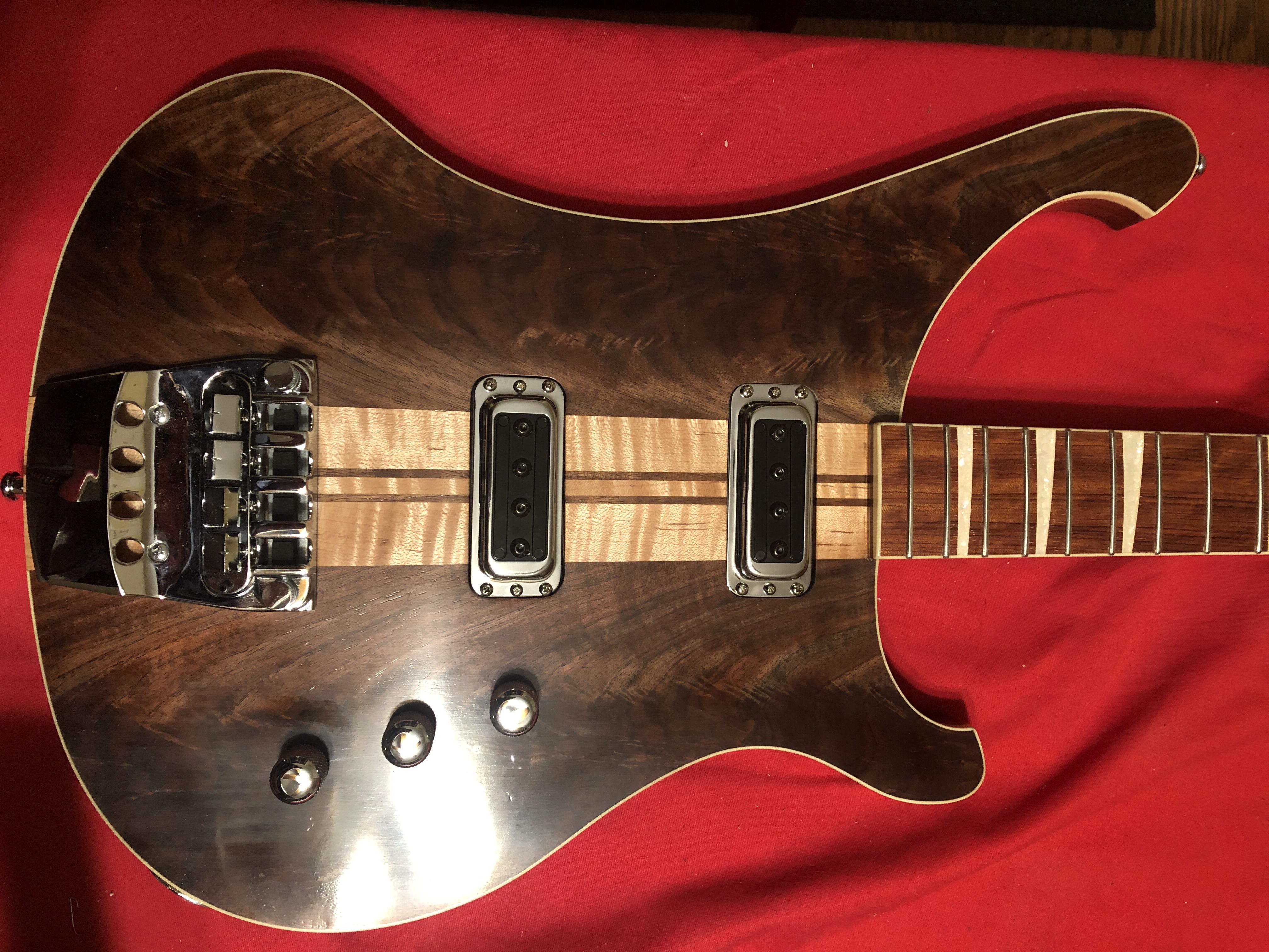
Pups in after some last-minute pain. I used the chrome pup covers to make a template, turns out the raw metal pup bases the chrome cover screws to are every so slightly bigger than the cover footprint, had to file them a little to fit my super-tight pup routes. Might want to leave a hair more leeway next time! I used foam weatherstripping insulation (1/2" thick) instead of springs, and drilled out the pup bases to use Fender style chrome pickup height screws, which I had to shorten to 1" length. I'm a little unhappy with this setup, you can "squish" the pups down by finger pressure, and they don't seem to spring back as nicely as I'd hoped. Add actual springs? How is it done on a real 4004?
FGiGUtP.jpg


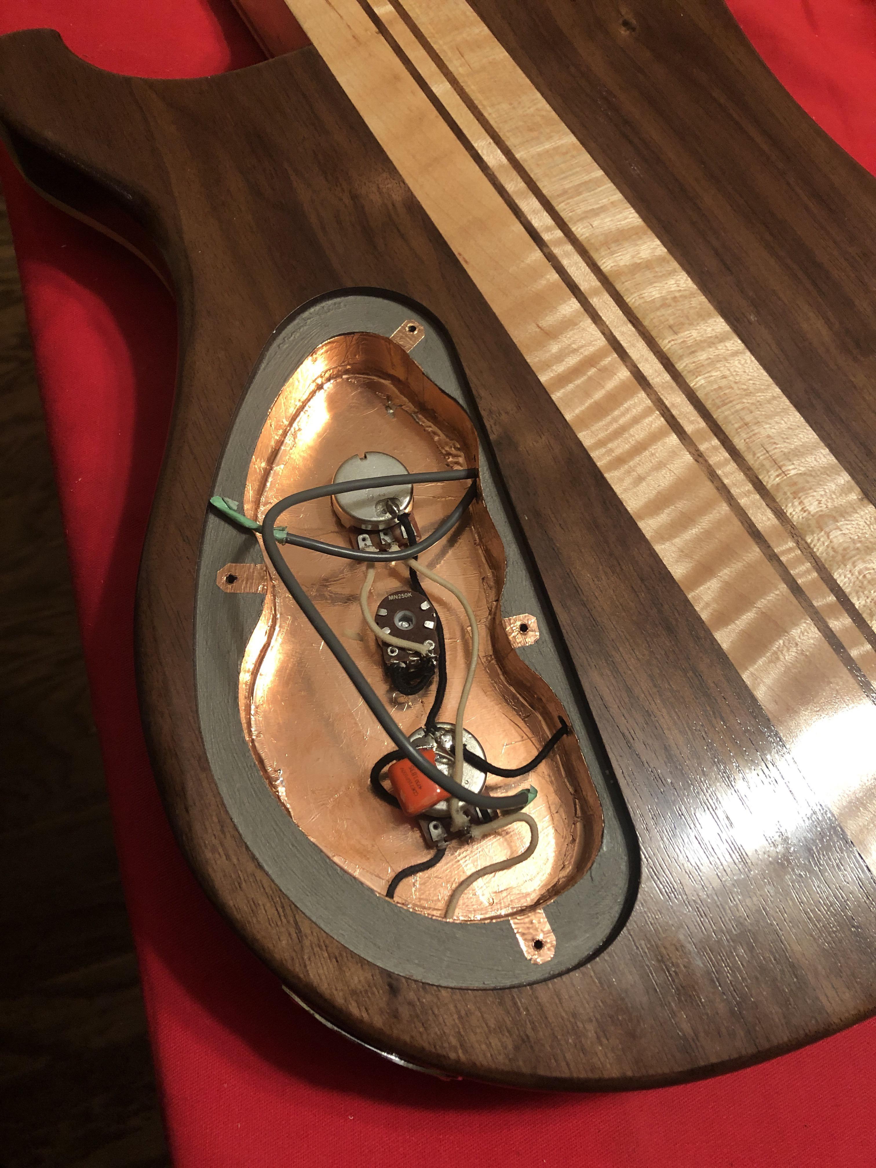
Electronics cavity, in retrospect kinda oversized, but I already had a Stewmac cavity cover routing template so......
2YqvhoB.jpg


The pup wires are hot and ground in one grey sheath. I could just splice a piece of wire to pup ground and solder to pot backs as shown (notice how I chickened out on the Star ground!), or split the gray wire cover up a bit to reveal a length of bare ground wire. Advice?
 
Last edited:
That's the same blend pot I use in 4004 harnesses. I solder the ground wire to the side of the pot. I always have pots zeroed out when I solder on them so that I'm not hitting the plastic stop cam inside with direct heat from the soldering iron. I always solder jumper wires onto the blend pot terminals to solder my pickup wires to since the pot terminals are so close together.
 
Is the ground of your output jack in contact with your shielding? If so I wouldn’t bother with soldering a wire on, tightening the pot down onto the shield will ground it.
Given the (slight) possibility of contact oxidization years into the future, I'd suggest soldering a ground wire to the jack, just to make sure there are no surprises later on....
 
Looking at the photo, you have already grounded the other 2 pots, so they will be grounding the shield through their cases, so you are already ok.

Stick a meter between the case of your little central pot and the ground of your output, I bet you have continuity
 
It’s only necessary for people who don’t know what the heck they are doing electronically, like me! It’s disgraceful, I know. Nothing much intimidates me about Luthiery any more, I know I can hack and fake my way through just about any woodworking task, but electronics still feels like smoke and mirrors to me. At the moment, the copper shielding is only connected to the output jack ground incidentally, so to speak, by the pots touching it. I should add a wire soldered to copper foil going to the ground on the output jack?
 
  • Like
Reactions: Rôckhewer
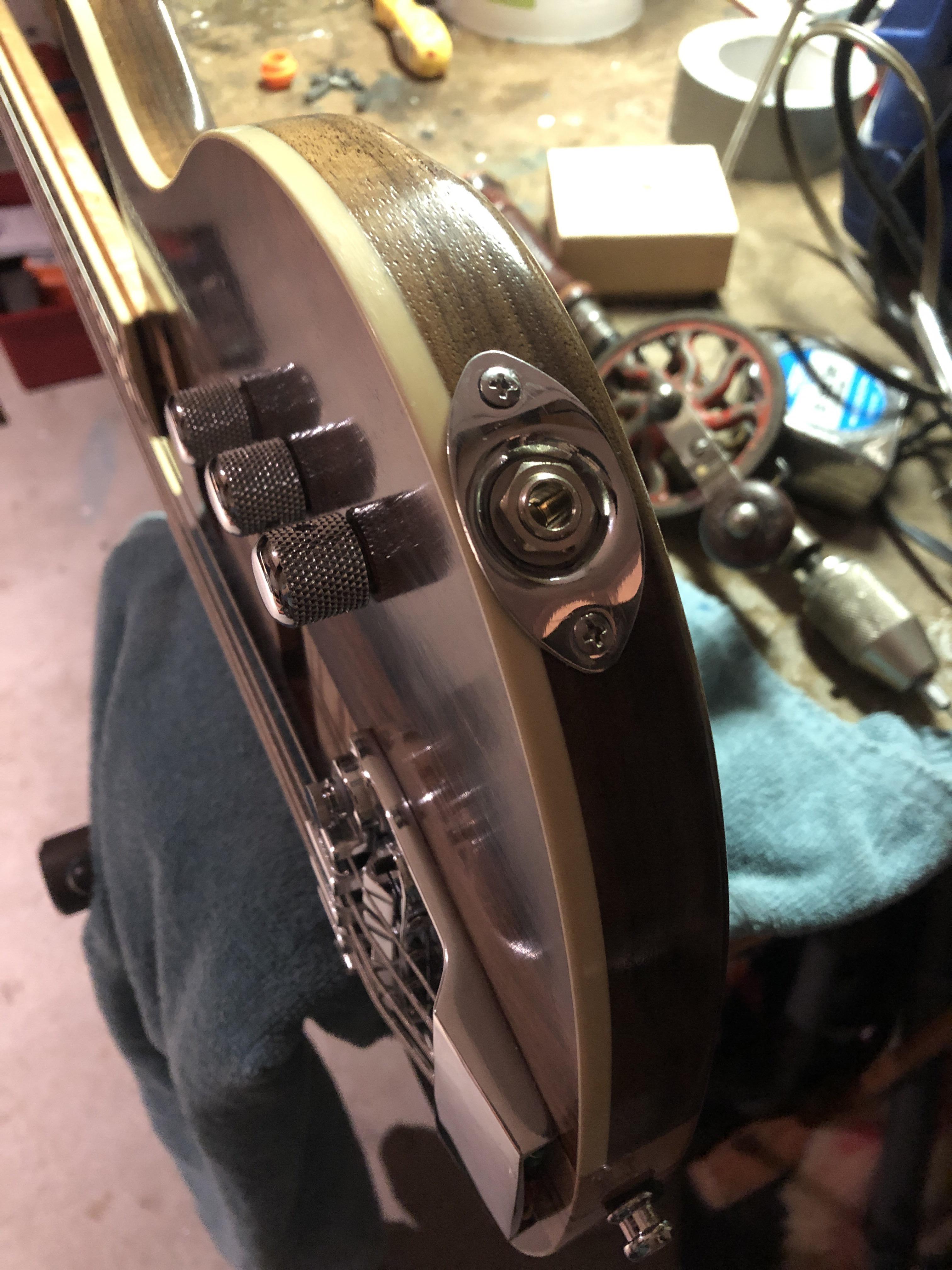
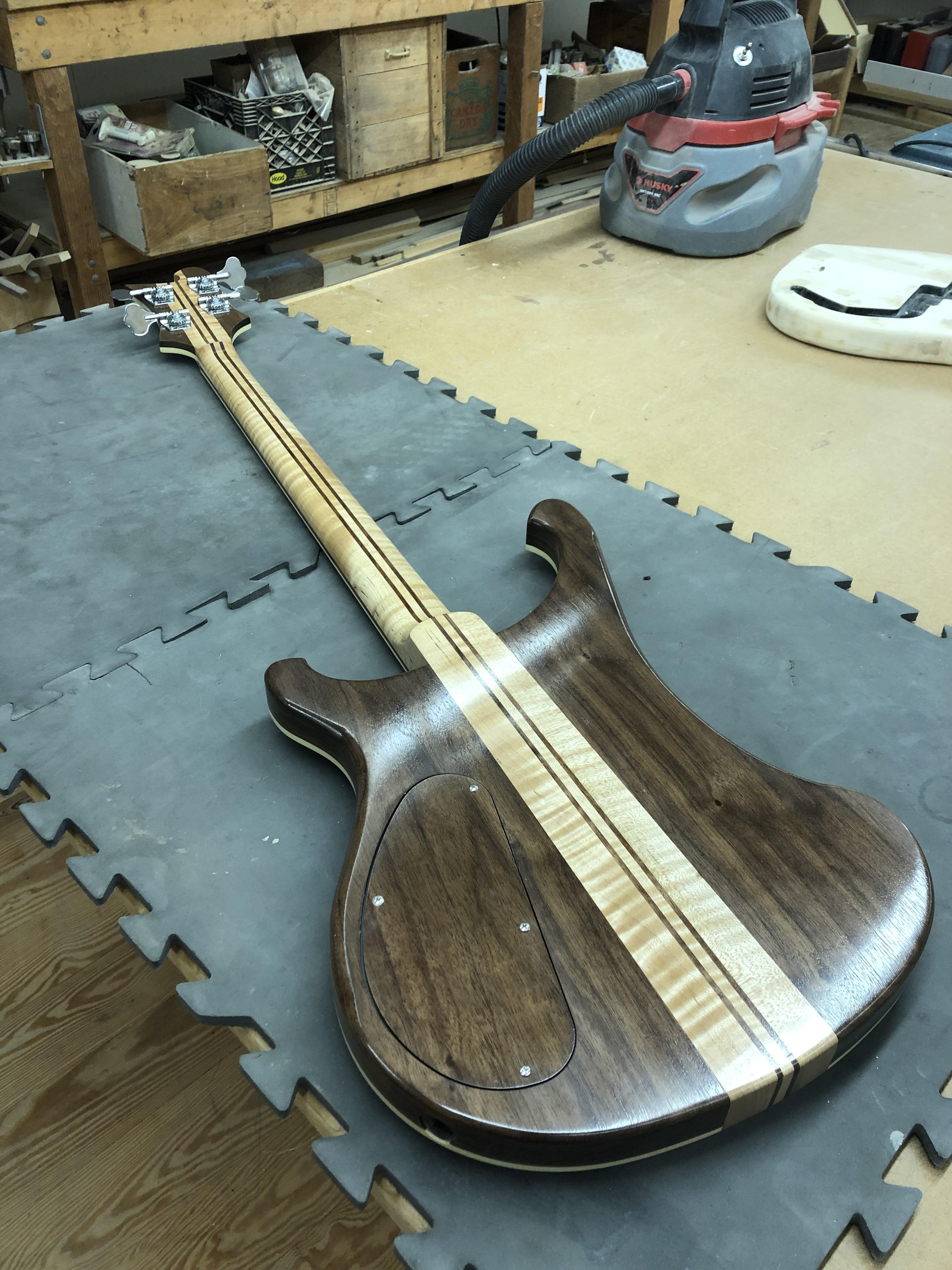
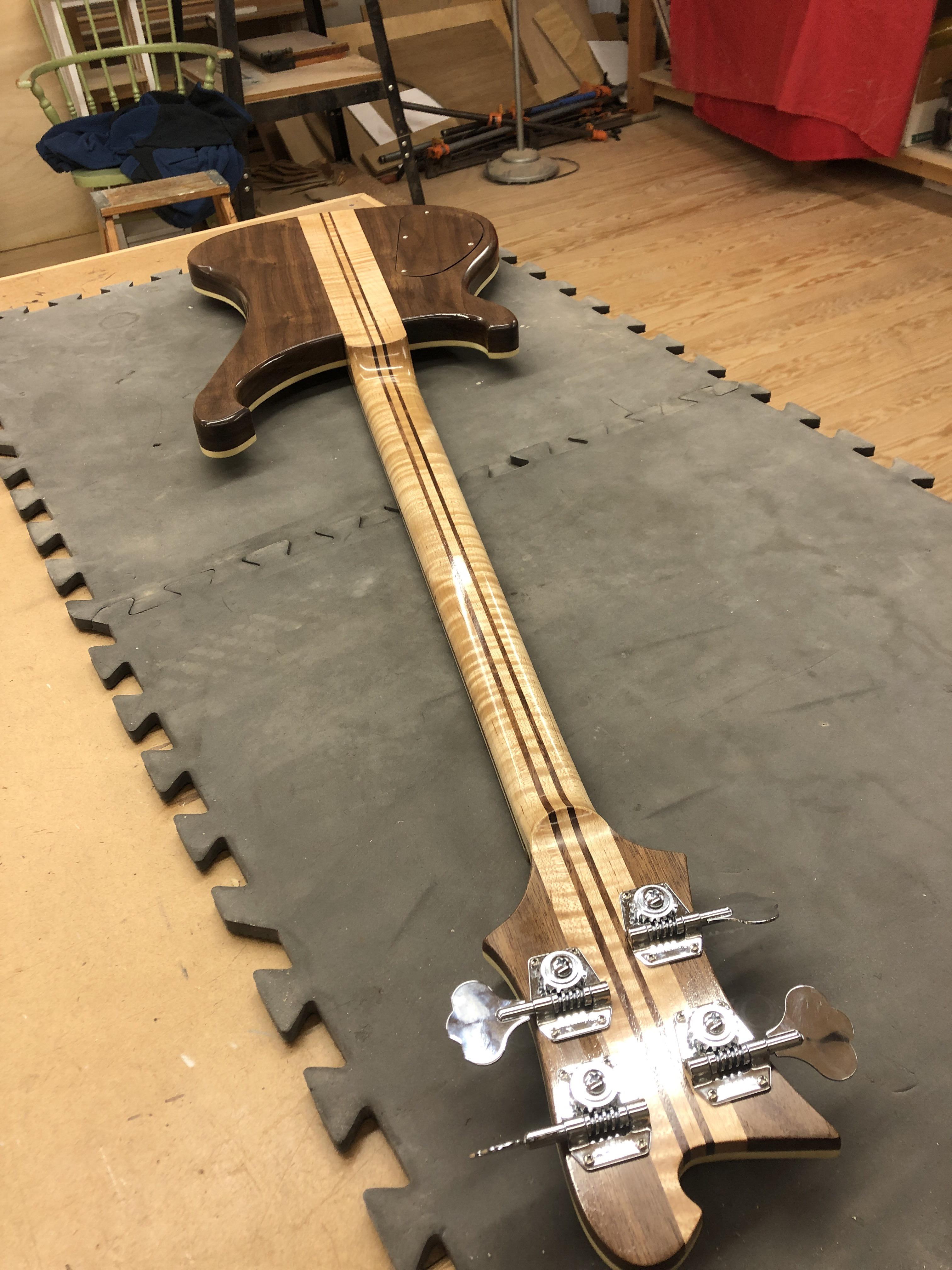
Ugghhhhh...... Got totally bogged down in the whole Tru-Oil experience. I had it all up to a nice satin sheen, but no.. have to buff it up a little. Bam! Buffed right through the oil finish on the front. Had to re-do it, but the pollen that permeates every surface on Cape Cod found its way into the finish. Repeatedly. I'm not entirely happy with the result, I think I'll take another crack at the front finish in the fall when the pollen subsides, but I am well and truly OUT OF TIME on this one. My son graduates from Mass Maritime Academy in two weeks, so it's pencils down.
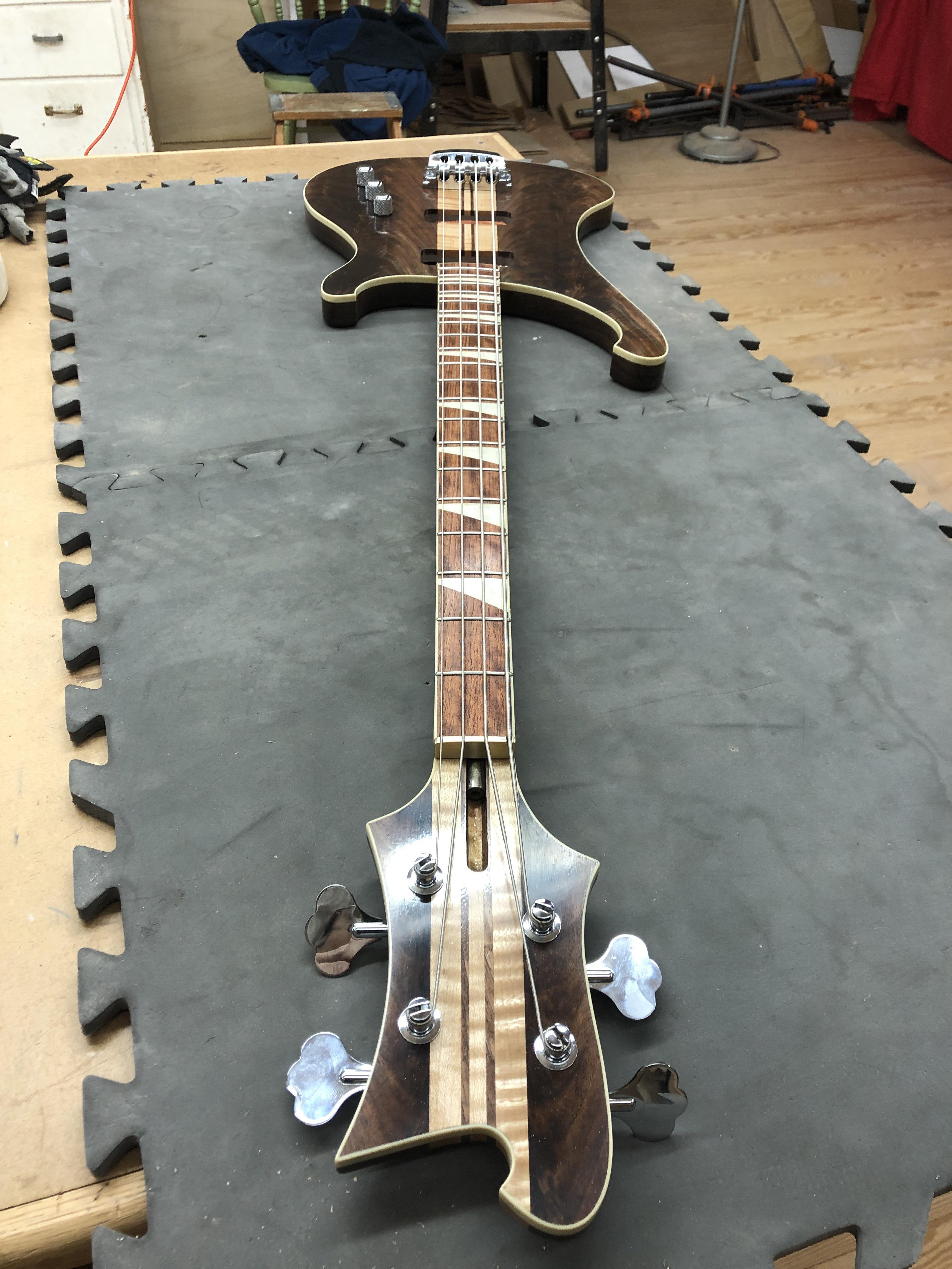
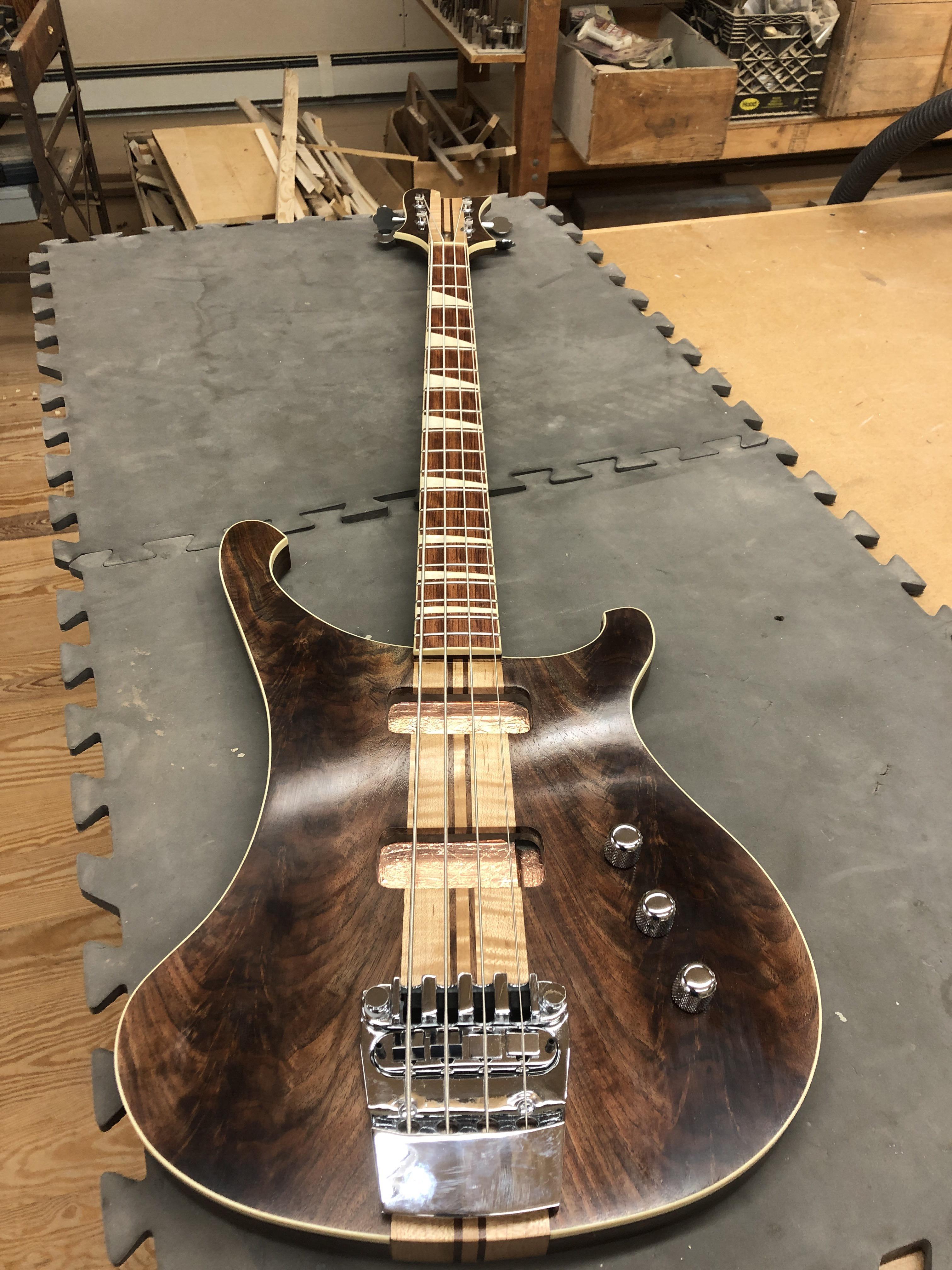
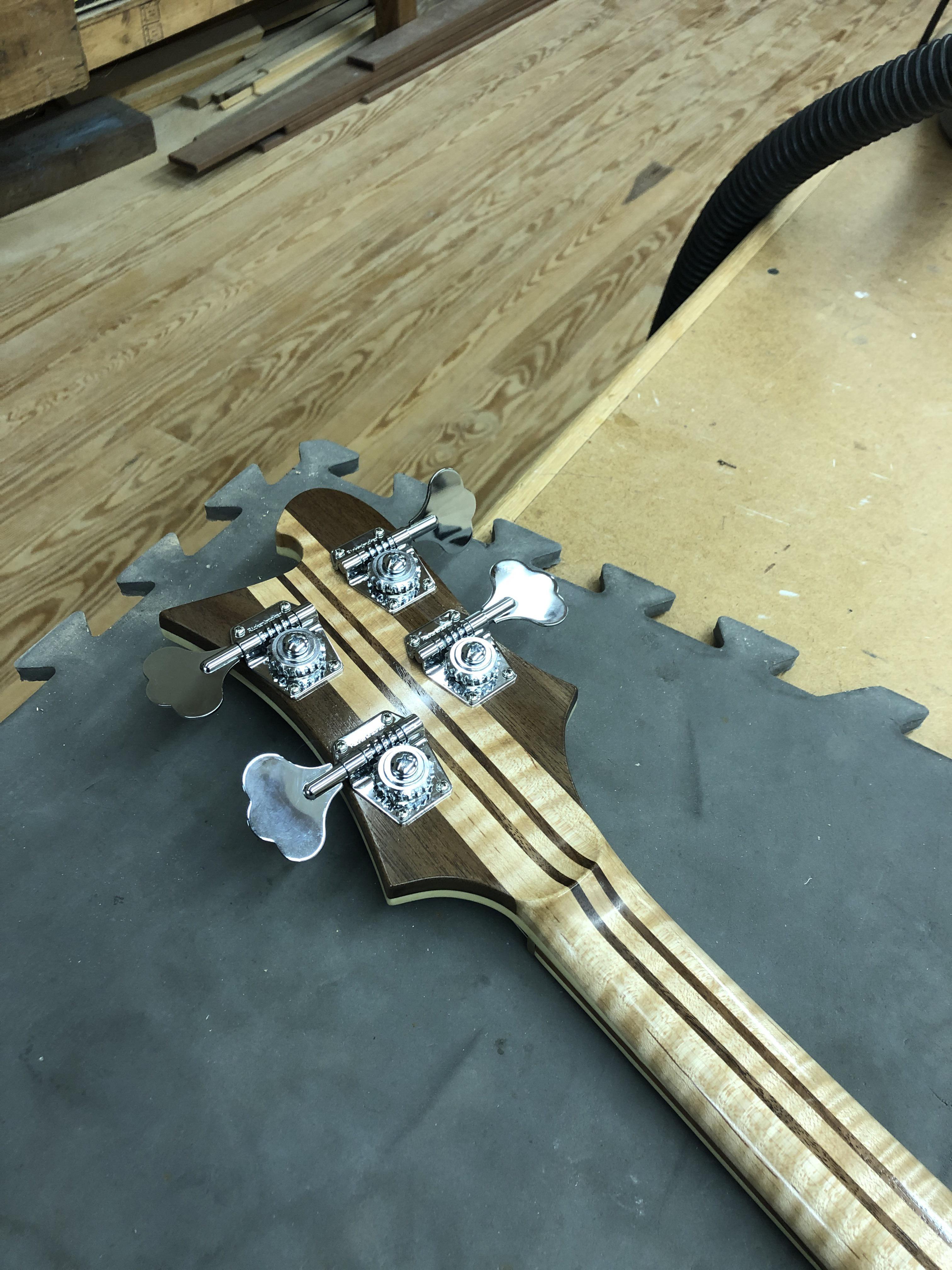
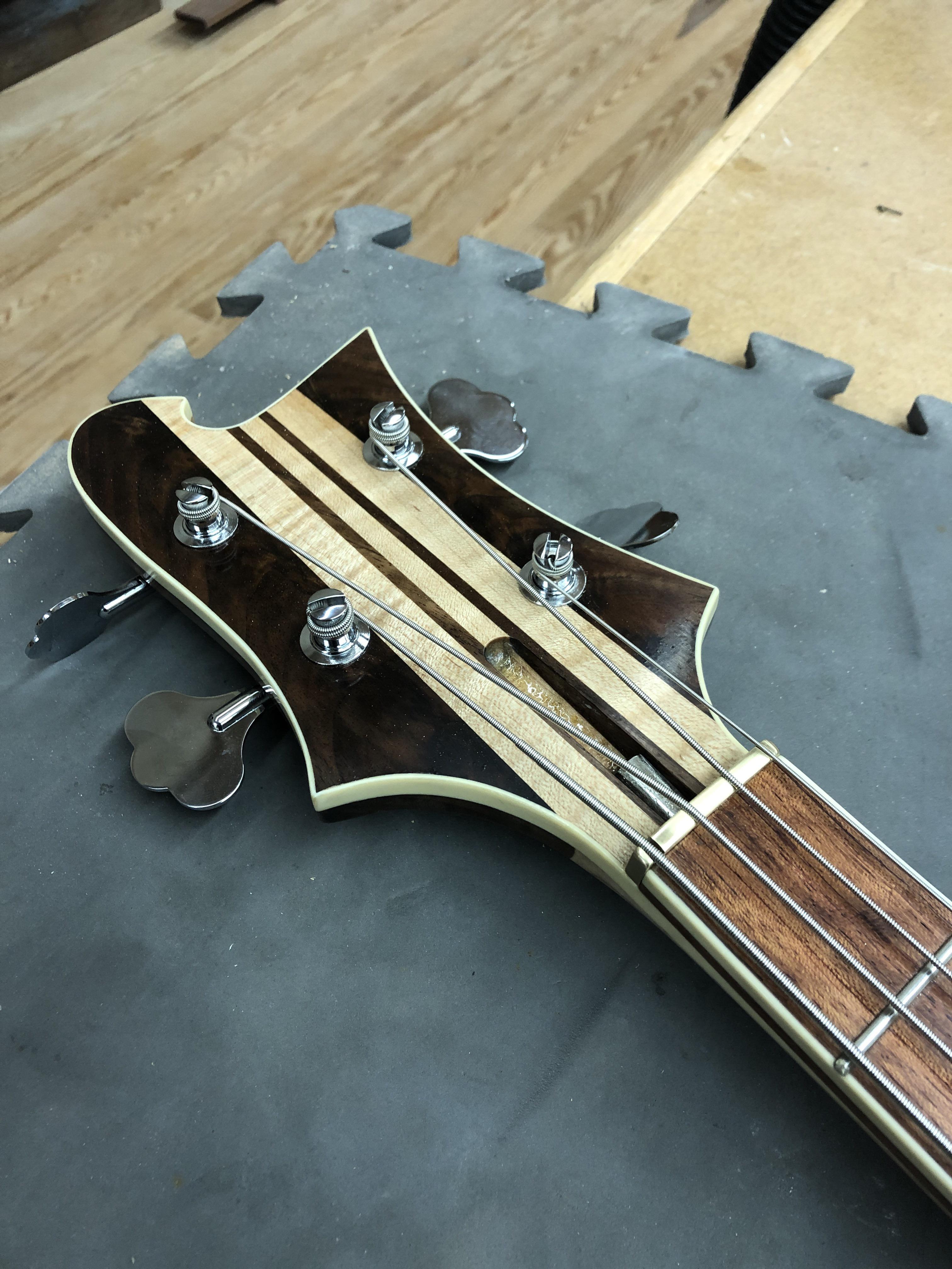
Here's where it stands, all I have left to do is filing slots deeper in the brass nut, a tedious trial and error process. and finish wiring it. Might need some advice when I get to that.
1smls8N.jpg

TbUM7mO.jpg

LofttS2.jpg

4cOgnMo.jpg

eD58o1j.jpg

ESV8lcO.jpg
Faboo!
 
  • Like
Reactions: Gilmourisgod
the copper shielding is only connected to the output jack ground incidentally, so to speak, by the pots touching it.

It's not "incidentally". The copper shield electrically connects anything mounted to (or through) it to anything else mounted to it. I never ground the pots. I connect all grounds together, and if I shield the cavity, I know it's grounded because the pots are mounted through it, grounding it. Test it with a meter. Just make sure you have a ground going to the shield somewhere. I usually just connect (solder) a wire to it, when I bother to shield a control cavity.
 
The pup wires are hot and ground in one grey sheath. I could just splice a piece of wire to pup ground and solder to pot backs as shown (notice how I chickened out on the Star ground!), or split the gray wire cover up a bit to reveal a length of bare ground wire. Advice?

Sorry, I missed this question. I would not just splice a wire to the pup ground without splitting that grey wire cover to expose a length of bare ground wire. Unless you are real good at soldering, it's likely that the heat of your soldering will melt insulation, both on that outside wrap, and maybe inside, shorting the ground to the center conductor. I'd definitely expose some of that braided or twisted bare shielding/ground wire from the pup, and pull it away from the center conductor before soldering. I *always* do that, and I consider myself pretty good at soldering.

The end of the pup wire should look something like this before soldering anything to it:

wire.jpg