Uh-oh, can you clarify?Unfortunately that's not the correct orientation though.

Enjoy the benefits of a premium membership!
Upgrade Account
-
TalkBass has been independent since 1998. Add your voice.
Create a free account to reply to discussions, view embedded media, and browse with fewer display ads.
Join free Log in
Want zero display ads or expanded classifieds tools? Compare plans.
You are using an out of date browser. It may not display this or other websites correctly.
You should upgrade or use an alternative browser.
You should upgrade or use an alternative browser.
The Passinwind Open Source Preamp
- Thread starter Passinwind
- Start date
More options
Who Replied?
- Dec 3, 2003
- 23,039
- 45,877
- Disclosures
- Designer/Toaster Tech @ Passinwind Electronics
Uh-oh, can you clarify?
In the orientation shown in your picture all the logos and numbers on the breakout boards should be right side up. When using the original straight pinned pots this might've have been more obvious, I guess. I'll get some pics up in here in the morning, sorry for the hassle. You may be able to fix most of the functionality with a little surgery on the boards and a few jumpers without having to desolder the breakouts, but I won't have time to figure that out until a bit later.
Beyond that, nice work and good idea on the power distro!

No worries, I have a nice desoldering station. Appreciate the help.

Hey Charlie, if you are still around and wouldn't mind answering another question: I was just getting caught up on the V4 designs and noticed on the V4 LPF module section it says "LPF Module with Gain Leveler and Inverter, not for standalone use". Just curious why isn't recomended to use the LPF on its own, given it has the frontend inverter/gain stage and all.
BTW: thanks again for posting these designs!
BTW: thanks again for posting these designs!
- Dec 3, 2003
- 23,039
- 45,877
- Disclosures
- Designer/Toaster Tech @ Passinwind Electronics
Hey Charlie, if you are still around and wouldn't mind answering another question: I was just getting caught up on the V4 designs and noticed on the V4 LPF module section it says "LPF Module with Gain Leveler and Inverter, not for standalone use". Just curious why isn't recommended to use the LPF on its own, given it has the frontend inverter/gain stage and all.
BTW: thanks again for posting these designs!
It'll work OK-ish but if using a high impedance source the large feedback resistor required to get to unity + gain isn't ideal. It works a bit better to use the non inverting LPF with a separate low impedance inverting stage for gain control. I could add a gain adjuster directly to the non inverting one, but I tend to prefer keeping the first stage as quiet as possible, just because. I'll put up a board share and schematic for the non inverting one as a standalone thing soon, along with whatever final version of the two pickup mixer stage I settle on. User feedback on the lone two filter onboard build I've cut loose has been extremely positive, but I'm still quite sure it can be improved.

It'll work OK-ish but if using a high impedance source the large feedback resistor required to get to unity + gain isn't ideal. It works a bit better to use the non inverting LPF with a separate low impedance inverting stage for gain control. I could add a gain adjuster directly to the non inverting one, but I tend to prefer keeping the first stage as quiet as possible, just because. I'll put up a board share and schematic for the non inverting one as a standalone thing soon, along with whatever final version of the two pickup mixer stage I settle on. User feedback on the lone two filter onboard build I've cut loose has been extremely positive, but I'm still quite sure it can be improved.
Thanks Charlie!
Are you talking about the input impedance of that gain stage (R2, 8k87) being very low? Indeed, you probably wouldn't want to put a pickup directly on there. However, the 50K-ish feedback in that stage shouldn't be large enough to be a problem.
Ultimately that doesn't apply in my case as my pickup already has a unity gain buffer on it. I was actually going to skip that whole gain leveler/inverter section and just use the LPF portion to the right, starting at R5. I also have a separate inverter stage on the output (technically a balanced output so both inverted and non inverted are there) so don't need inversion on the input.
I will keep an eye out for the non-inverting update. Maybe that would suit my application better.
Last edited:
- Dec 3, 2003
- 23,039
- 45,877
- Disclosures
- Designer/Toaster Tech @ Passinwind Electronics
Thanks Charlie!
Are you talking about the input impedance of that gain stage (R2, 8k87) being very low? Indeed, you probably wouldn't want to put a pickup directly on there. However, the 50K-ish feedback in that stage shouldn't be large enough to be a problem
Once you scale impedances you're typically looking at at least a few hundred K ohms on each side and that will be much noisier than necessary. If you are feeding the LPF from a buffered front stage it'll work fine, but that's already what the non inverting one is/does, all in one compact and well integrated board. As I've said many times, we have to look for bottlenecks and fix them first. Fancy low noise opamps don't help a bit if the rest of the circuit doesn't support them properly, for instance.
Once you scale impedances you're typically looking at at least a few hundred K ohms on each side and that will be much noisier than necessary. If you are feeding the LPF from a buffered front stage it'll work fine, but that's already what the non inverting one is/does, all in one compact and well integrated board. As I've said many times, we have to look for bottlenecks and fix them first. Fancy low noise opamps don't help a bit if the rest of the circuit doesn't support them properly, for instance.
That makes sense about the impedance scaling part. I agree that low noise amps coupled with bad design does nothing good.
I should have explained better that my questions weren't exactly about using the LPF standalone. I am actually looking at inserting the LPF section into the middle of an existing preamp, but I wanted to be sure I understood why you had indicated that it shouldn't be used standalone. All good now.
- Dec 3, 2003
- 23,039
- 45,877
- Disclosures
- Designer/Toaster Tech @ Passinwind Electronics
That makes sense about the impedance scaling part. I agree that low noise amps coupled with bad design does nothing good.
I should have explained better that my questions weren't exactly about using the LPF standalone. I am actually looking at inserting the LPF section into the middle of an existing preamp, but I wanted to be sure I understood why you had indicated that it shouldn't be used standalone. All good now.
Cool. I'll be leaving this thread for at least a month now, see you all then.
This is basically how I'll be wiring it up:Was there a block diagram posted somewhere in the thread?
Input jack-->Footswitch in-->HPF module-->Bass/Mids module-->LPF module-->Footswitch out-->Output jack
I have the individual board schematics, but didn't see how they are connected once built and in the pedal. I went back a few pages and think I found the answerBlock diagram? Do you mean schematic?
https://www.talkbass.com/threads/the-passinwind-open-source-preamp.1259692/page-74#post-28161325
Thanks! I do plan to ground the enclosure, but I'm using Neutrik PCB-mount jacks and adapter boards which are electrically isolated, so I'm probably looking at adding a ground screw to the case or bottom cover.Really nice looking work, Sanj. Your picture is (I think) the first affirmative picture in the thread for which way is up for the sub boards on the dual pots, for we visual learners.
Are you grounding the enclosure to the circuit? Where in the circuit, the first input jack to the case?
Neutrik adapter boards at OshPark:
OSH Park ~
The jack can be mounted on either side of the board as needed, the ferrule side is to the right in this image.
Attachments

Success! I now have a fully functional test unit, many thanks to Charlie for his patient assistance. On to working on the final packaging. 


- Dec 3, 2003
- 23,039
- 45,877
- Disclosures
- Designer/Toaster Tech @ Passinwind Electronics
Success! I now have a fully functional test unit, many thanks to Charlie for his patient assistance. On to working on the final packaging.
View attachment 5402194
Looking good!
@Sanj: your persistence and hard work has been invaluable in moving things closer to finally wrapped up, thanks a ton for that. The latest schematic revisions are all up on Github now, and I'm really hoping the newest version of KiCAD will eat my homework a lot less often. I've had to constantly double check rogue annotation changes over the years, and failing to do that this time created a lot of unnecessary work for both of us, I'm afraid.
Meanwhile, I've been working on beta testing some delay and chorus circuits using the new Cabintech "digital BBD" chip. Not bass oriented in any way, just a fun what-if exercise for my acoustic guitar. Details on that chip are here: Digital BBD concept looking for comments and beta testers . I'm already getting results that sound better than any of the $$$ rack delays I used to own, especially the noise floor, and all the peripherals can be relatively simple analog circuits if desired.
Well, it's been a fun and circuitous 4-1/2 months, but I finally finished three working V4 pedals! I used a TBS1 relay switcher from Stomp Box Parts in order to implement remote footswitching, which ended up working great. Grounding of the enclosure was accomplished with a 1/4" ring terminal under the Mids switch with a short jumper wire to the input jack ground. Spencer at AmplifyFun did a superb job printing the enclosures. My little power distribution board made wiring the power for all of the boards tidier. The three filter boards are attached to the bottom cover using heavy-duty adhesive-backed plastic hook-and-loop, which also serves to insulate them. Once again, a huge thank you to Charlie for all of the effort making this possible.
(Note: All of the pot breakout boards are flipped upside down from the way they were originally intended to be, but electrically they are wired as intended. I just found it easier to have the wires hanging off a bit.)
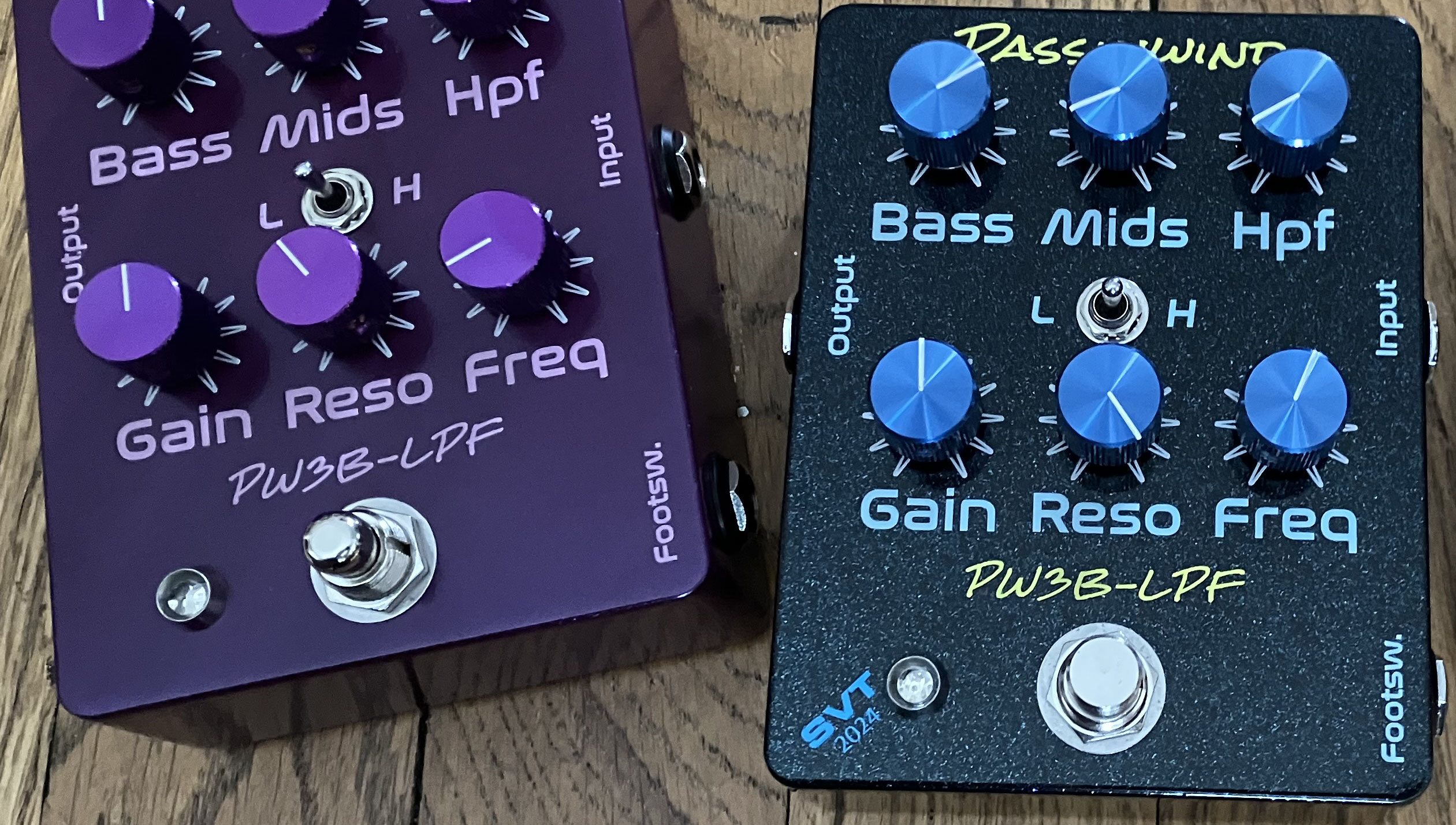
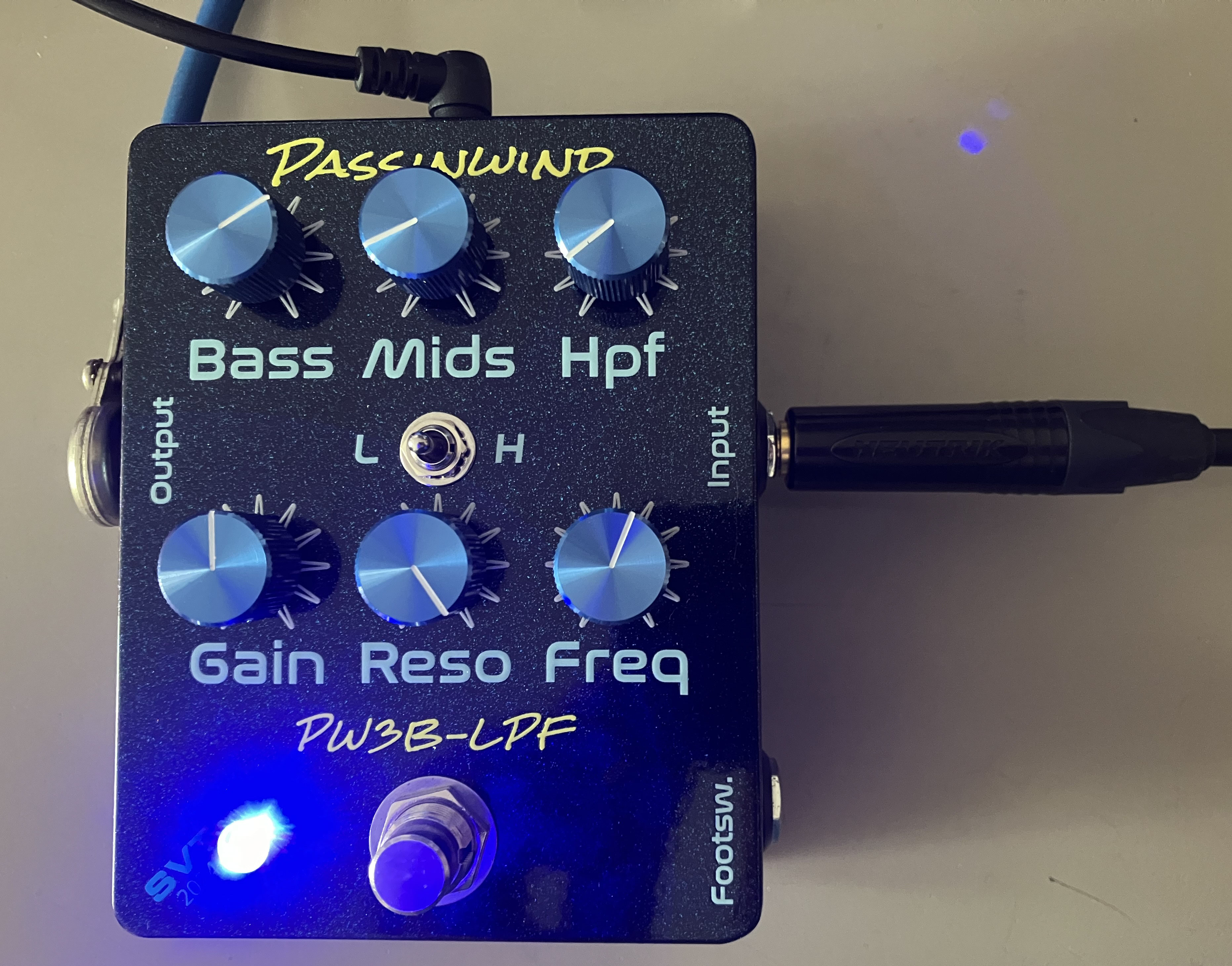
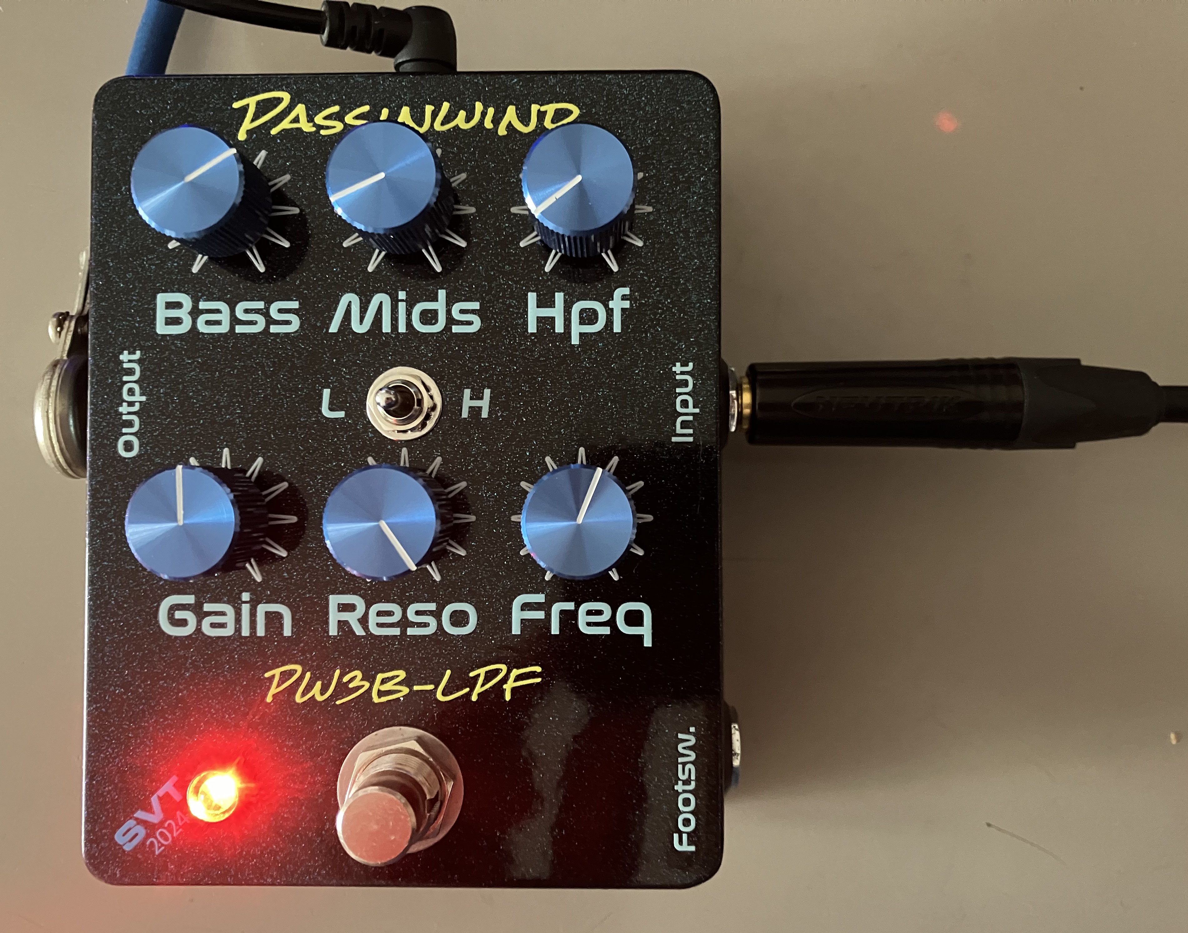
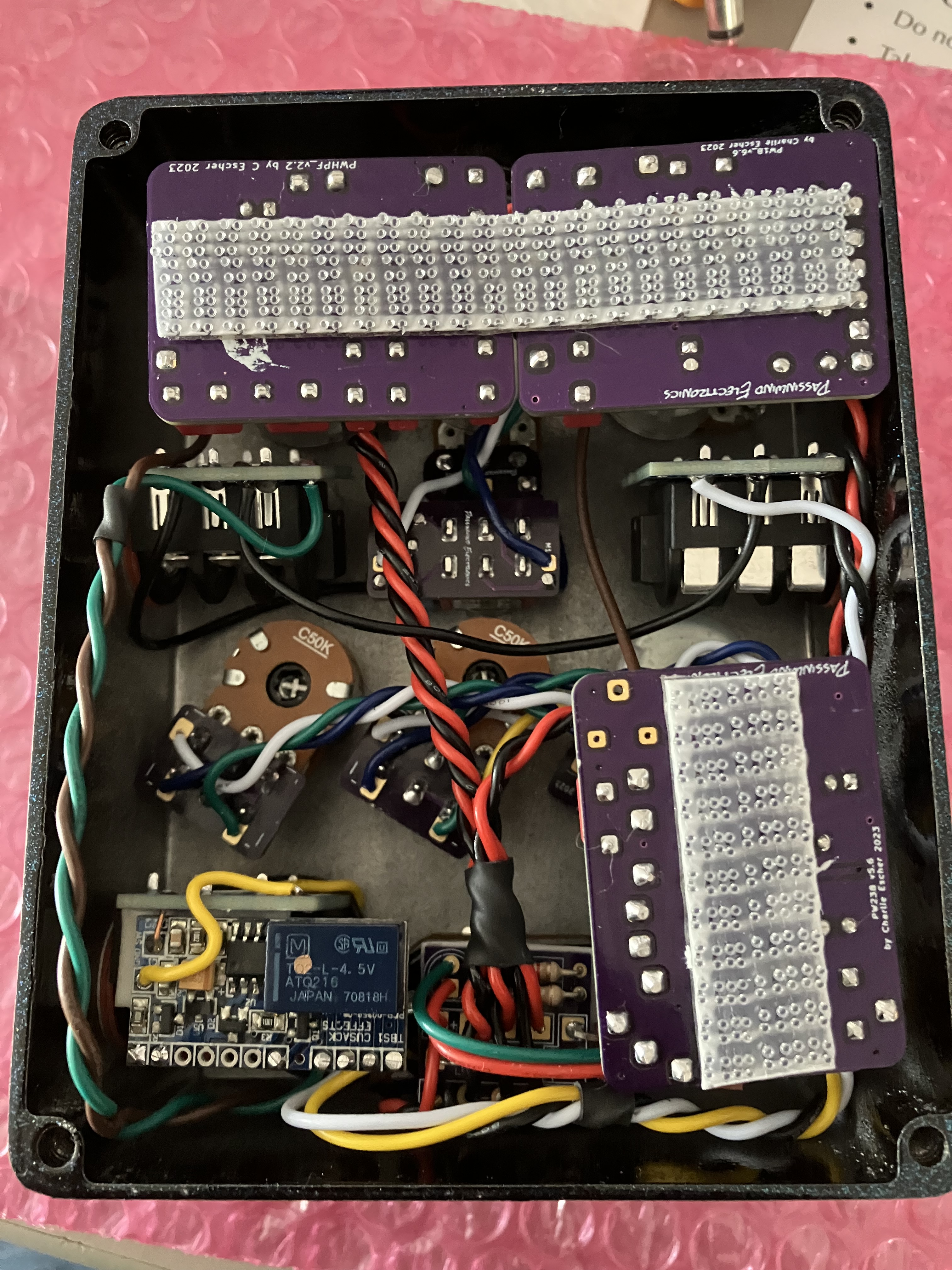
(Note: All of the pot breakout boards are flipped upside down from the way they were originally intended to be, but electrically they are wired as intended. I just found it easier to have the wires hanging off a bit.)
Last edited: