
Thanks for the compliment. It is meant to be art as well as a tool. I've got no problem with an instrument being "just" a tool, but, there's so much opportunity to make it more than that, so why not? I know that when I'm playing SK1 and I glance down at my neck, I see those fret markers and that flame maple, and I want to play something great.
As far as caring for instruments, I try but I'm not in the museum-piece mindset. I know that I can be clumsy, that the headstock definitely will get banged, etc.--so I try to take care of an instrument, but don't let it hold me back from using it. I wonder how many Ritter Royals ever see a gig.
_______________________________________
Pickup Shells cont'd
I left off with the covers glued to the backer/extension wood. Here's the board cut up. Since I have only one shot with these matching covers, I am proceeding cautiously as I can. I cut apart the board,
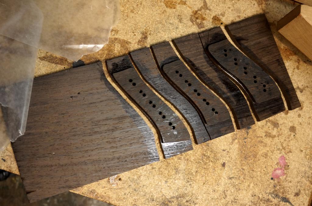
and then i wrapped the upper "template" portion of each shell with two wraps of blue tape. Then bandsawed pretty close to the tape, then edge sanded very close to the tape, to prepare for routing.
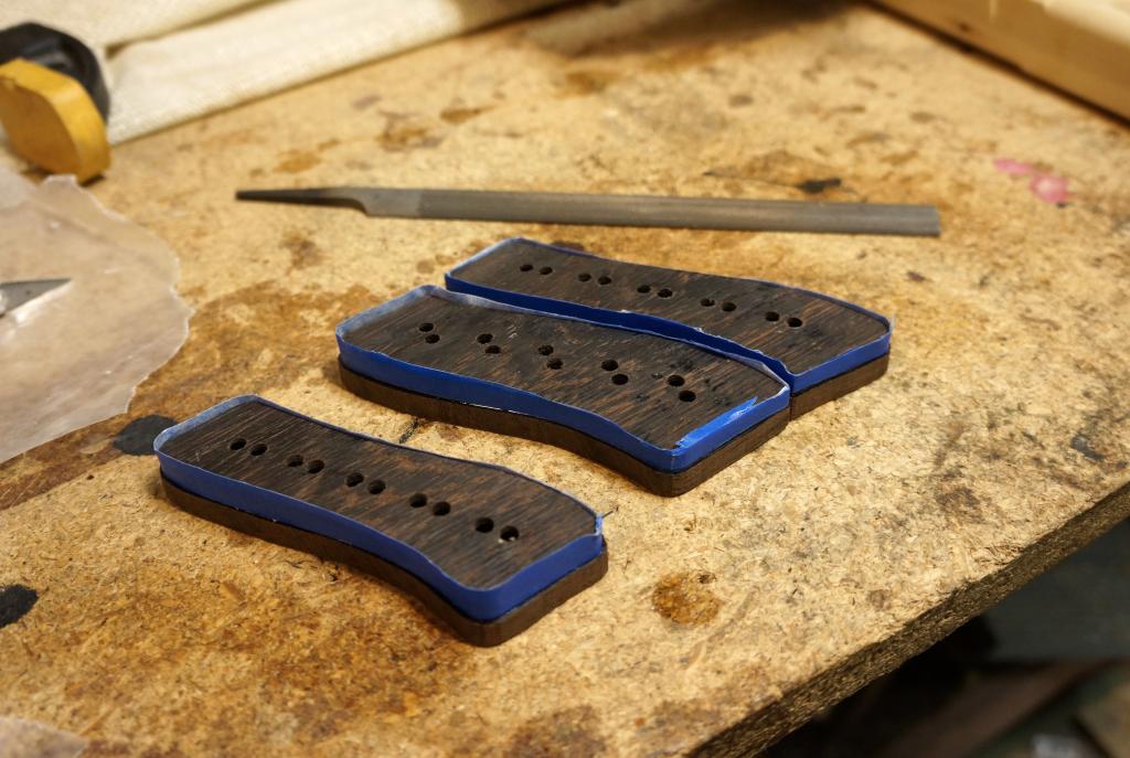
I had seen something once about doing small detail routing using a pin near the bit, to pivot the workpiece off of. So I set up something similar, using the rounded corner of a small piece of wood.
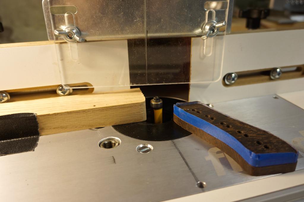
Then I routed to the tape, removed one layer of tape, routed again, removed the final layer, and finished. I used the rules for grain direction and climb routing etc. as well as I could, and got only a small bit of tearout.
Then I remounted the shells to the caul, and drilled the holes for the anchors, and used forstners to re-open the back to the cavity below that I had already routed. On anchor hole opened to the side of the shell when my drill table decided to rotate (dangit!), but it should be hidden out of view.
Then I had to clean up the openings. I used a chisel, with no problems until I was squaring up the last corner on the first shell, and - CRACK! %$&#$*#£†£ª•†∑¶!! One end split off. So, I will have to glue it back together. I'm not too worried because it broke along those wenge stripes, which should make it invisible. As matter of fact, when I was gluing on the back extension wood, glue had gone by capillary action up a crack in one shell front that I didn't even know was there, so it repaired itself.
I cleaned up the remaining shells using a dremel, which, should I do this again, I will start with.
Then I tried fitting a pickup in a shell. No go! Since my holes were exact-sized, and (as it turns out) the holes in the spacer that I used as a drilling template are oversized a bit, plus the fact that these are split coils which are not necessarily perfectly aligned, it didn't fit. I had a recommendation to drill the holes to the next larger fractional size, but I thought .016 larger may be too much, so I got out a #9 drill, which splits the difference, and opened up the holes. It came closer to fitting, and after some work with a rattail file, i got it in.
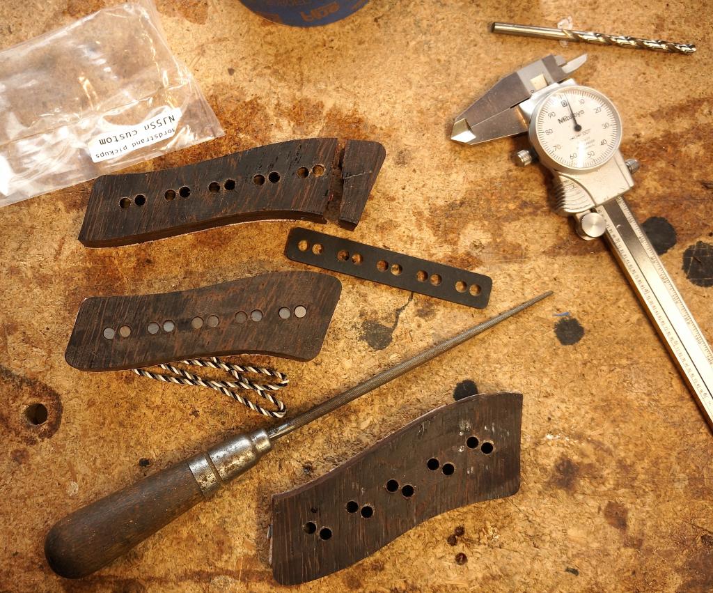
I future, I would measure the holes in the spacer, and use the largest possible drill that fits them, whatever that is.
The polepieces are sitting a little below the wood, which is fine since the faces haven't been sanded yet.
As far as caring for instruments, I try but I'm not in the museum-piece mindset. I know that I can be clumsy, that the headstock definitely will get banged, etc.--so I try to take care of an instrument, but don't let it hold me back from using it. I wonder how many Ritter Royals ever see a gig.
_______________________________________
Pickup Shells cont'd
I left off with the covers glued to the backer/extension wood. Here's the board cut up. Since I have only one shot with these matching covers, I am proceeding cautiously as I can. I cut apart the board,
and then i wrapped the upper "template" portion of each shell with two wraps of blue tape. Then bandsawed pretty close to the tape, then edge sanded very close to the tape, to prepare for routing.
I had seen something once about doing small detail routing using a pin near the bit, to pivot the workpiece off of. So I set up something similar, using the rounded corner of a small piece of wood.
Then I routed to the tape, removed one layer of tape, routed again, removed the final layer, and finished. I used the rules for grain direction and climb routing etc. as well as I could, and got only a small bit of tearout.
Then I remounted the shells to the caul, and drilled the holes for the anchors, and used forstners to re-open the back to the cavity below that I had already routed. On anchor hole opened to the side of the shell when my drill table decided to rotate (dangit!), but it should be hidden out of view.
Then I had to clean up the openings. I used a chisel, with no problems until I was squaring up the last corner on the first shell, and - CRACK! %$&#$*#£†£ª•†∑¶!! One end split off. So, I will have to glue it back together. I'm not too worried because it broke along those wenge stripes, which should make it invisible. As matter of fact, when I was gluing on the back extension wood, glue had gone by capillary action up a crack in one shell front that I didn't even know was there, so it repaired itself.
I cleaned up the remaining shells using a dremel, which, should I do this again, I will start with.
Then I tried fitting a pickup in a shell. No go! Since my holes were exact-sized, and (as it turns out) the holes in the spacer that I used as a drilling template are oversized a bit, plus the fact that these are split coils which are not necessarily perfectly aligned, it didn't fit. I had a recommendation to drill the holes to the next larger fractional size, but I thought .016 larger may be too much, so I got out a #9 drill, which splits the difference, and opened up the holes. It came closer to fitting, and after some work with a rattail file, i got it in.
I future, I would measure the holes in the spacer, and use the largest possible drill that fits them, whatever that is.
The polepieces are sitting a little below the wood, which is fine since the faces haven't been sanded yet.