• TalkBass has been independent since 1998. Add your voice.
    Create a free account to reply to discussions, view embedded media, and browse with fewer display ads.
    Join freeLog in
    Want zero display ads or expanded classifieds tools? Compare plans.

WBO 2024: Bari-metric Pressure

Dec 26, 2018
234
836
UK
This be the thread for my entry to this.

Best Bass for ... wookies and Munster-butlers who want a break from the bass.
Category: Non-Bass

TLDR: Its a baritone. Sort of.

I started to write a long screed detailing my predicament, but I could see it would be too much for Herman Melville, so I'll try to write a short version. Yes; this is the short version.

I'm nearly 2m tall (6'8"). I have big hands. I want an electric guitar for chord work and treble melodies (and punk riffs with way too much gain).

I used to play an acoustic when I was much younger but converted to the bass. I bought an electric several years ago but couldn't consistently fret cleanly on the chords (I'd get a duff chord with undesired muted strings maybe 1 in every 6 chords). I assumed it was proficiency-related as I remember having the same problem on the acoustic which went away with practice and experience. It didn't go away with practice and experience; it got better, but the error rate was still 1 in 10 or so. I didn't let it get to me; I could still play monophonic melodies / licks and crunch power chords, so that was a lot of the itch scratched.

One day, I was at a friends' house. His fiance called and had forgotten her phone. Could he run it in to her at work? Sure. Can you stay here and guard the house for 20 minutes while I'm gone? Sure. He had a nice Takamine acoustic in the living room. I started noodling. No duff chords. In over three minutes. ***? I measured the nut. It was 45mm. The two electrics at my house were 42mm and 42.5mm respectively. When I was back at my parents' house for Christmas, I measured my old acoustic. 45.5mm.

Case solved.

On top of that, scale length helped. I've had the opportunity to play the Reverend Descent RA (26.75" scale) and the PRS SE 277 (27.7" scale) and really liked them. Truth be told, if the nut width was just a millimeter wider on either of these, I could probably live with them.

To paraphrase Churchill: Building your own guitar is the worst option except all the other available ones, which are:

a.) Find and buy one that suits you. Difficult, rare, potentially expensive, very good chance of not being exactly what you want. They're out there; they're just not easy to find.

b.) Pay a luthier to make a custom one, either the neck or the whole instrument. This always works and may well get you the instrument of your dreams. Mind that first cheque, though; it's a doozy. If I had four grand to spend on a guitar, I'd buy a bass.

c.) Get a neck from Warmoth. They do wide and baritone, but not both at the same time. On top of that, shipping to the UK is crazy (it doesn't cost £110 to ship a stick across the Atlantic). There are arbitrary configuration decisions (the super-wide comes with a side access truss rod). The options are limited. I still salute them for trying.

d.) Convert a 7 string. Most 7-strings come with 48-50mm nuts; most come with 26.5"-28" scale lengths. The logic is simple: Buy a cheap / second-hand seven-string, replace the bridge, replace the nut, optionally replace the pickups, optionally remove a tuner and plug a hole; you're pretty much there. It's cheap, relatively low hassle and functional. There are plenty of second-hand sevens floating around for not too much cash, and you can get a decent brand-new one for not much more than a six.

One major problem: the tram lines. On most guitars / basses, there's usually 2-4mm of fingerboard width outside the outer-most strings and that distance remains relatively consistent as you go up the frets. On a converted seven, unless your six strings follow the splay of the fingerboard (which will make them a long way apart as they reach the bridge), they will usually use a 6-string bridge, which means the tram lines will get wider and wider as you go up the frets, often with as much as 5/16" (8mm) outside the outer-most strings. Can you live with that? Cool. If not ...

d v2.0.) Modify a 12-string. @2groggy suggested this after the build was started. In his own words...

Here's one more way to get a wider nut width - start with a twelve string neck and cut six tuner holes off of the headstock. You won't find an off-the-shelf bridge to match, but I bodge up my own floating bridges anyway.

I'm using this trick on all three of my builds.

Worth more than one thought for anyone who doesn't want to set their own scale length.

e.) Shave down a 7-string. Same as (d) except you manually fix the problem with the fingerboard width by reshaping the neck.

Catch number one: There tends to be all sorts of things inside the neck of a 7-string guitar (2 truss rods, multiple reinforcement rods etc.). If any of these is anywhere near the outside of the neck when you're taking that extra width off, you're going to have an expensive parts donor.

Catch number two: This is one step closer to being actual luthiery and some people will say that, if you're at this point, you may as well go the whole hog and ...

f.) Make your own neck. Get a donor body that takes a bolt-on neck and build a parts guitar, except that you contribute the neck part yourself.

Advantages: complete control over everything including string spacing and scale length.

Disadvantages: Unless you move the bridge (could be difficult on a strat body, for example), you're stuck with the pickup spacing and the bridge/body relationships of the original body. You have to contend with design decisions that you didn't make (e.g. fitting your neck to a pre-existing neck pocket, rather than fitting the pocket to the neck -- unless you re-cut the pocket). Elephant in the room: Oftentimes, making the neck is the hard bit. The body's often the fun part where you can run a little bit freer. If you're prepared to do the neck, especially if you're reconfiguring substantial other parts and relationships with the guitar, then you may as well ...

g.) THIS BUILD!!
(aka Make your own)

I've been going round and round between (c), (e), (f) and (g) since before lockdown. I kept returning to 'making-do with my Ibanez'; getting frustrated; exploring the options; hating the options; escalating the options; de-escalating the options; second verse same as the first. It's reached the point where, if I just get on with it, I'll spend less energy. So that's what we're doing.

I started designing the guitar in mid-2021, and the design got a lot more detailed and serious in June of last year. I was partly held up because I had a lot of woodworking 'commissions' of the build-a-gate/make-a-bookshelf variety as the supply situation improved after Covid, but I finally managed to clear and clean my 'workshop' (it's the size of a single-car garage, if that car was a SMART), and I'm clear to go. The timing of this build-off convinced me to get my arse into gear.

There's only one catch:

I've never built a stringed instrument in my life.

That's technically true, but it's slightly deceptive and clickbaity. I've been tech-ing my own and my friends and acquaintances' stuff for a long minute. I've built bodies (well ... two); I've built necks (errr ... one), and I've done a number of re-frets (actually, I have done a number of refrets ...). I've also wound pickups and am halfway decent at electronica.

So I'm in a bit of an inverse experiential position when it comes to this build. Normally, when a player wants to build a guitar, they're full of geekery and enthusiasm about the history and heritage of their particular object of desire and they're usually a pretty good player, but they struggle with how they're going to get their woodworking skill and tools to the point where they can do it. I'm the opposite. I don't really give a F about the difference between a '58 and a '59 neck, or a pre-CBS vs post-CBS strat (amps are another matter ...), and my guitar chops could use a hell of a lot of work (almost as if I need a guitar ...) but, without wanting to tempt fate too much, there's nothing about the woodworking that scares me, except maybe the belly contour. I've been woodworking for over 20 years (occasionally semi-professionally), and the first few years were mostly with hand-tools ("Ah were a-hand-cuttin' dovetails while thee were a nipper, lad").

In truth, with my youthful enthusiasm for the bass getting re-kindled in the late noughties after I'd learned the fundamentals of working wood, and with my slowly-but-steadily growing workshop, I've sort-of known for a while that I was heading towards building my own stuff. I always thought I was heading towards a super-long 5-string fretless, though (actually, I secretly thought I was heading toward a 4/4-size Guarneri-style upright, but we don't talk about that in public ...). I never thought the first complete attempt would basically be a guitar.

But that's what it is. Even if it's a total failure it'll serve as a shakedown test run for the upcoming fretless if nothing else.

<accent>Let me show you its features:
partschott.jpg


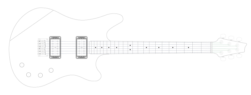
It's not a particularly interesting instrument outside of its outsized nature. In trying to keep it simple, but also have fun with the design, I settled on something that's essentially a cross between a telecaster and a double-cut Les Paul. It has a custom offset shape that came from (a) making a guitar that was supposed to be a light-baritone to begin with, rather than retro-hacking baritone-icity onto an existing chassis, and (b) fixing everything I didn't like about the Fender Jaguar (and I really like the Fender Jaguar aesthetically; it just doesn't remotely work for me on a practical level).
bariscaleproto_700_04_h_small.jpg


Specs:
(I totally didn't steal half of these from Beej)

Scale length: 27.56" (this looks 'exotic' until you realize it's dead-on 700mm)
Nut: 46mm (1 13/16" -- Yup; I'm awkward. I don't want 48mm and I'd like slightly wider than 45mm). In complete transparency, I've already made the template and it came out at 45.88mm, which is AOK with me. That's the advantage of rolling-your-own or paying a luthier; you can do exactly what the hell you like and, right now, I can't afford a luthier.
Frets: 22
Vibrato: None (Gotoh GTC-101 Bridge)
Pickups: 2 x PAF Humbuckers, probably Alnico-5; probably slightly overwound, but I've made the body templates so that, if this actually ends up working for me, I can make a P90 or Tele-style single coil version in the future.
Fingerboard radius: 254mm (10")
Nut: Undecided. I have both TUSQ and brass available. It will be one of those
Tuners: Gotoh SG301 (01 style levers); no locks; no nothing
Neck Joint: Bolt-on (6 bolts)
Truss rod: Dual-action 460mm
Body: 2-piece Utile (Sipo)
Body top: 12mm (15/32"); 2-layer lamination made from 9.5mm (3/8") somewhat-figured wild Sycamore (that's Sycamore Maple to the North Americans) and 2.5mm (3/32") Walnut separation layer. Probably dyed (but I might just pop the grain and run away ...)
Neck: 1-piece Utile. Grain-through straight-neck F-style construction, but with 3x3 headstock
Fingerboard: Gabon Ebony with some nice ribbon figure
Electronics: Passive
Controls: 4 knobs, 1 switch. 1 x volume; 1 x tone per pickup
Knobs: Black and Gold Speed Knobs
Jack: Switchcraft 1/4" with Gotoh mounting plate
Strap Buttons: Gotoh EP-B3 Oversized
Finish: To-be-decided. Depends on what I do to the top. Currently leaning to matte 2k on the body and tru-oil on the neck, but it's subject to change.

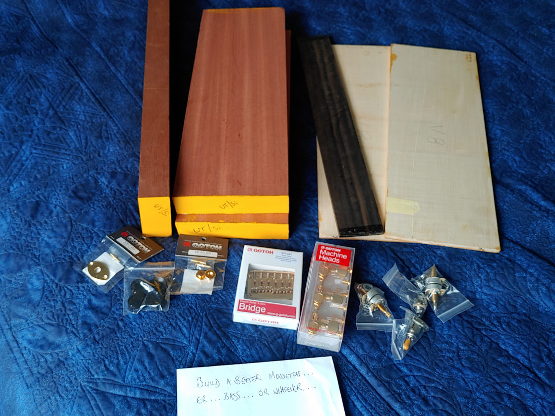
As you can see in the image above, I made the 'mistake' of ordering gold hardware. This wasn't originally my plan; it's just that, towards the end of the Covid lockdowns, when I went to get the bridge, they were out of stock on black and, for some reason, had the gold on a really good discount. I don't know what it's like where you are, but Gotoh hardware is never discounted over here, so I grabbed it without really bearing in mind that it would sort-of commit me to buying gold for most of the other stuff. I'm leaning into it now. It'll be fine.

That'll do for now, I think. If you made it this far, thanks for reading.
 
Last edited:
This is a very relatable build! I'm "only" 6'3", but I also have big hands and landed on 44-45mm nut width for my own builds after some experimentation. Just gives a little extra space for chord work. Some extra scale doesn't hurt either. I'll be following this for sure!

Here's a link to my entry from last year's WBO, following a very similar concept.
 
  • Like
Reactions: Quills
This is a very relatable build! I'm "only" 6'3", but I also have big hands and landed on 44-45mm nut width for my own builds after some experimentation. Just gives a little extra space for chord work. Some extra scale doesn't hurt either. I'll be following this for sure!

Here's a link to my entry from last year's WBO, following a very similar concept.

Thanks, man. For full accuracy, I'm not quite 6'8", but I can look someone who is pretty much in the eye.

That build is awesome; and inspiring (not least because I've got ABM headless hardware for the future fretless I mentioned above). Congrats. The belly carve is crisp-as-hell, too.
 
Watching the seasoned vets explode into activity is slightly disturbing, as I probably won't get properly going on mine until after Christmas, but we can recap what I was doing in the few weeks before the start deadline.

I thought we'd start with the most critically important part of the entire project: pickup rings. We begin with a humble 13mm (1/2") thick block of ebony, square and true ...

01_ebony_block.jpg


Using an already-made fixture, which will be making an appearance shortly, I used 12mm (15/32") transfer punches to mark the locations of the corners of the inner cavity. I then took an 8mm (5/16") brad-point bit and drilled out the holes based on those punch marks. This means the outer extents of the holes are 2mm inside the final cut line.

02_block_drilled8mm.jpg


I set up a birds-beak fixture and used a coping saw to get rid of the waste. The yellow lines mark the outer extents of the holes, not the final cavity; they're a don't-go-beyond marker:

03_block_coping_beak.jpg


It then goes over to the small router table to meet the aforementioned fixture:

04_jig_post_cope.jpg


It gets secured in the fixture using a variation of hold-down clamps. Because of the forces involved (class 3 levers), the thumbscrews have to be cranked pretty hard. Note that, because the fixture itself was used to mark the hole positions in the first place, (a) the correct corner has to reference between the fences (upper-left here), and (b) only 2 sides of the block are roughly-to-size at this point; the other two are free:

05_jig_pre_rout.jpg


The fixture and router table do their thing:

06_jig_post_rout.jpg


... and the bun pops out of the oven (it's been rotated 180-degrees in this image from its orientation in the fixture):

07_block_post_rout.jpg


Calipers, a shooting board, a no 7 plane (who says I don't have a jointer?) and sanding boards get the other two sides to dimension:

08_block_post_shooting.jpg


I wanted to put roundovers on the outside of the corners, and I wanted them all absolutely identical, which somewhat ruled out doing them by hand.

I didn't get a picture of this step, but I put square corners on three pieces of scrap plywood: one was 9mm (~3/8") baltic birch; the other two were 18mm (~3/4") construction ply. Using a flat surface (the router table), and a square, I then sandwiched all three of them together with the birch in the middle, clamped them to form one laminated square corner, and fed them through the router table sideways with a 3/8" (9.5mm) radius roundover bit in it. This prevented tear-out/wandering, and meant that the 9mm baltic piece came out looking like this:

09_38s_roundover.jpg


I then took that corner piece and, using the bandsaw / superglue / scraps and screws, built the following fixture around that corner:

10_roundover_jig.jpg


11_roundover_jig_loaded.jpg


I then took it back to the router table and let the templating bit do its thing:

12_roundover_jig_used.jpg


All four corners done:

13_block_post_ro_jig.jpg


The block ends were a little beaten-up after the previous shooting-board operations (honesty: the plane wasn't as sharp as it should have been for ebony endgrain; it's since been sharpened). I planed a straight edge on some scrap and used a square to align it to the horizontal belt sander plate. Some 150-grit took care of the ends:

15_squaring_block.jpg


I then marked the hole positions and took it to the drill press. It's important either to maintain cross-grain pressure here with a vice or to drill gradually (or both) as ebony likes to split under internal pressure (don't ask how I know):

17_block_drilled.jpg


Next came the operation I was kind-of dreading. I could have done this on the bandsaw; I could have used a fine, gentleman's saw; I could have used a small ryoba and, on paper, those would have been superior choices as they have very fine kerfs which would give me more wiggle room.

However: this is one of those jobs where reliability and tactile feedback are more important than theological correctness, and the hard-point, 14", 14ppi, Spear and Jackson toolbox saw (#notsponsored) is my most-used handsaw for cutting <16mm (<5/8") plywood / laminates. Despite its limitations and cheapness, it has the major advantage that I know exactly how it's going to behave in my hands and what it's doing as it's doing it. Its wider kerf meant that I had much less margin for error, but my skill with it is higher, so I was less likely to make an error.

Split the block; very carefully:

18_block_resaw.jpg


19_block_resaw_split.jpg

20_block_resawed_inner.jpg


Whew.

I then needed to take away the saw marks and get them down to thickness. I was targeting 4.5mm (~3/16"). I have a couple of sets of decent drill bits, so I used those as common-man gauge pins in combination with my router fence and the spindle sander to set the distance and act as a poor-man's drum sander.

21_sander_thicknesser_setup.jpg


If you ever do this, remember:
(a) Using the same reference face on the fence, pass each piece through twice, rotating 180 degrees between passes; this mitigates any vertical taper the sander might put in the workpiece thickness.
(b) Never go with the spin (climb cut), always against, otherwise the set-up can fire the work-piece out like a cannon. It can still fire it out (kick-back) if you do it the correct way, so stay out of the way and only take small increments off at a time. Slowly.

It didn't take too many iterations; I think I did 3 x 0.5mm increments (5.5mm -- which didn't really take much, 5mm and 4.5mm) -- there just wasn't that much leeway after the the split cut. When they came out of the final pass, they were about 4.2mm instead of 4.5mm. This is the effect of the sponginess / bulb-taper in the spindle-sander; it's just not that accurate.

After they were done, I took them to the drill press and put countersinks for the screws I wanted to use in the corner holes using an over-large drill bit. Finished:

22_post_thickness_countersink.jpg


Snatching defeat from the jaws of victory

And now ... some slightly annoying news: I may not use them.

I had fun making them and problem-solving the steps along the way, but I don't know how I feel about their final form. I think I may have done one 0.5mm take-down too many; they would be better at 5mm, I think. They feel a little flimsy at 4.2mm and their overall style suggests a chunkier thickness.

I don't know; I'll see how I feel nearer the time. I have some Hosco ones which are smaller and more elegant while feeling about the same strength, if not stronger. I should probably have leaned into their bulkier nature rather than trying to replicate industrial minimalism. To be continued ...
 
Last edited:
TLDR: Template-making. If you're not interested, I won't hold it against you.

Okay. Finally got the templates finished this evening (several days late ...).

You may have seen a couple of these pics elsewhere in the past week or so -- especially in "What's on Your Workbench?" -- if so, my apologies for the repeats -- but this update will give the context and bring everything ... well ... up-to-date.

When I knew I was finally going to try and do this build, I took the liberty of having the plans printed on A0 paper. It cost me 14-odd quid (next time I'll remember that line colour plans are a lot cheaper than block colour plans ...), but it gave me three body and 3 neck outlines at precise 1:1 scale to screw-up on.

Because of that, one of the first things I did was create a couple of reference boards. These are just solid pieces of scrap (one was 6mm SPF ply, the other was a planed pine offcut) with a set of plans glued to them, then poor-person's-laminated with packing tape. The sole function of these is so that I don't have to go back-and-forth to the computer to check approximate dimensions and relationships; I can just measure them off the plans as I need without leaving the workshop. It saves messing around unfolding large pieces of paper, too.

I used spray contact adhesive to do the reference boards but I didn't like it; it was a bit too stringy and gummy (it actually worked pretty well, though); so I made the mistake of using PVA to make the body master template. I used a bit too much and the paper puckered up, so I returned to using the spray adhesive for the neck as it was less awful. Fortunately, it didn't really change the dimensions; just created some water creases. I'll invest in some 3M for the next one.

Reference boards and body master roughly cut to size on the bandsaw:

O01_bodyTemplateAndReferenceBoards_s.jpg


After that, I spent a while shaping and refining the body master on the belt/spindle sander. The body master has some reference points (centre-line, pickup / safe alignment pin locations, cavity extents etc.) that need to get transferred to the child templates, so I carefully located them with a sharpened awl and drilled 2mm (5/64") holes through the template.

I'm spending the extra time making master templates out of 9mm (~3/8") MDF and child templates out of 12mm (15/32") MDF partly because: (a) I want to try the full 'chain' process to gauge how much hassle it is; and (b) if this guitar works for me, there's a reasonable chance I might make another one (single-coils) and a remote chance I might make as many as four more (spare PAF (vintage wind), single coil, P90, very-high-output PAF). There's no chance I'm going to make that many without ruining at least one template, so some redundancy separation might be helpful.

The neck master was a little different. I started by using a straight edge to dial-in the sides of the master. The first image shows setting a second straight edge so that I can index the first one back in the same location with double-sided tape on it.

01_straight_edge_neck_clamp.jpg


02_straight_edge_router.jpg


At this point I needed to make sure my neck template was going to work with the router bit (Radian 19mm (3/4") shallow template bit) that I was eventually going to use to cut the neck mortise, so I used the router bit in question in the big router to cut one side of a 'fake neck pocket' on some scrap construction plywood. I then took a spare piece of 12mm (15/32") baltic birch plywood and used the fake neck pocket as a template to mark out the correct curve on its corner. The oscillating belt sander and some sanding boards on a makeshift shooting board (bench hook) were used to bring the curve in:

metaTemplate.jpg


When I was happy with the fit, I then used the curve as a template to radius the rear corners of the master neck template:

03_neck_corner_radius_router.jpg


This finished the heel area of the neck master:

04_neck_heel_corners.jpg


I did the headstock area freehand on the spindle sander, but I courageously used a steel bar as a template for the nut transition to give me a buffer against sanding into the straight that I'd already cut with the router:

05_steel_neck_guard.jpg


I put three coats of shellac on the edges of the finished master templates and left them to settle for a couple of days.

I then wanted to test the neck master heel curves, so I used the master to cut an incomplete fake-neck heel on some scrap 18mm (~3/4") plywood, and then routed for the fake neck as if I was routing for a real neck on a different piece of plywood and tested the fit. Lo; 'twas >satisfactory:

01_neckJointTest.jpg


Then I took the masters, clamped them to 12mm (15/32") MDF, copied the outlines and transferred the index locations with a 2mm (5/64") transfer punch. I used the awl to enlarge any weak punch marks.

06_location_transfer.jpg


The bandsaw was used to cut close to the line and I then used the master templates for their intended purpose on the router table to create the child templates:

07_child_outlines_done.jpg


I originally outlined the extents of my body cavities using different-sized holes. Even though it would be a lot of work, the idea was to connect these holes with straight edges and a template bit in a router to give clean cavity walls. This design was all done before I had a spindle sander. I stuck with the original plan for a bit, in that I drilled the holes and rough-cut them with a jigsaw ...

09_cavity_holes_drilled.jpg


10_cavity_holes_jigged.jpg

... but then, except for linking the top two cavities, I ditched the router setup (the internal cavities are never going to be seen) and used the spindle sander with 60 and 150 grit spindles to bring them in. The spindle sander is faster than I'd thought, especially with 60 grit.

11_cavity_holes_spindled.jpg


I would not use this method in future. I think I'd print the cavities on card, cut around them with a knife, use a couple of indexing points to line them up on the MDF, draw around them onto the MDF, use a couple of entry-point/relief drill-holes, and then jigsaw and spindle sand the lot. It'd be much quicker. You could freehand the router, but I try to avoid that. What do you lads and lasses do?

The one exception is the control cavity. I might use a router on that. I quite like Tornelli guitars' method (cover plate). On this one, I just did the cavity cover very carefully. It's probably not quite dead straight, but if it looks very slightly amoeba-ish, I don't really care. There's not really much of a straight line elsewhere on the body anyway and if it looks only slightly home-made, that's kind-of cool.

I could also have been more aggressive with the cavity size -- they could be larger but it's my first complete build and I'm trying to stay away from the carve areas (arm rest / belly contour), the edges and the centre block. It being a baritone and that I'm probably going to put fat strings on it at some point, I'm being conservative with the safety margin. I'm also not super-concerned about weight; my main 5-string is over 10 pounds. I may not end-up excavating the cavity immediately behind the bridge; I'm silghtly concerned about how chunky / long the neck's going to be. On the flip side, I could excavate it and then fill it with epoxy if there turns out to be a problem.

The other thing about this process is: it's cool, but it's not necessary. The next planned build is kind-of a one-off and, with the spindle sander and the bandsaw, I think you can probably freehand it. If you're making more than one, though, templates make sense.

Anyway. Temporarily finito. To be continued after the holidays.
Merry Christmas, everyone.

11_templates_done.jpg
 
Last edited:
Ok. Back in the game ...
Not too much to see here; just stock prep and early-days stuff.

I always intended to take a week or so away from the shop after Christmas, but an unexpected visit and an even more unexpected leaking shower and repercussions kept me away far longer than anticipated. No matter; we're here now.

Firstly, Santa Claus brought me a pretty decent present in the form of a new 5"/125mm random orbit sander: DeWalt DWE6423.

I wouldn't normally post about it here except that there is whole slew of misleading text online about DeWalt's proprietary attachment mechanism and how you have to spend £20 on some adapter or other (DWV9000 and then maybe another adapter etc.) to get it to work with a shop vac. If by chance you're reading this from Google; this isn't true. DeWalt's proprietary adapter only works on the outside of the vacuum connection port. The inside of the connection port takes a standard 35mm (1 3/8") O.D. vacuum hose connector (see pic below). You only have to get your stuff to speak 35mm, you don't have to get it to speak DeWalt.

A lot of people just take the internet's word for things which are eminently testable at home. I nearly fell into this trap too except, when I went to the shop to codge-up a homebrew adaptor, it turned out that my vac fit just fine. No mods needed.

00_dewalt_dwe6423.jpg

Anyway, with that out of the way, on with the build.

When I pulled my neck blank out of storage, I found that it had developed something of a ... ... problem.

01_winding_sticks_twist.jpg


It was pretty flat when I got it, but somewhere along the way picked up a fairly chunky degree of twist. The person selling it said it had been seasoning for a year in indoor north-west UK conditions, but I'm not sure I believe them; I think it was fairly fresh off the boat. It's been on top of stretchers on top of a wardrobe in a fairly stable room for the last two and a half years, so I suspect it did the last of its drying there.

I had to set at it with a jack plane for quite some time to get it back to something approaching acceptable. It's actually better than it looks here; notwithstanding the amplification of the winding sticks, part of the mismatch is lens distortion while being slightly off-axis.

02_winding_sticks_flatter.jpg


I needed to get the neck blank down to a final dimension of 22mm (~7/8"). I'm not following Fender's numbers because ... reasons; not least that the body block is going to be thicker and I want a full 1" (25.4mm) thickness neck at the 12th fret to cope with heavier strings at standard pitch if need be and to accommodate my oversize mitts.

After sorting out the twist, I squared up one edge with jack and jointer planes ...

03_neck_edge_sq.jpg


... then took it over to the bandsaw to resaw it down to 24.5mm (~31/32"). This would give me 2.5mm (~3/32") leeway if it moved again.

04_neck_resawed.jpg


I then put it aside for five days to see if it did anything new with that mass / tension released. It didn't. So far so good. Mercifully, the body blanks had stayed nigh-on dead flat, but they came from a more reputable source to begin with.

I then needed to get the blanks down to final dimensions, which meant busting out the thicknesser. I wanted to keep snipe to an absolute minimum and didn't have any conveniently-dimensioned boards of a large enough size to act as shepherds through the planer, so I thought I'd try a trick I once saw David Picciuto of 'Make something' do and use small amounts of stock as snipe-stoppers.

The idea is simple(-ish). You get appropriately-dimensioned stock, make sure it has a planed, square edge, and cut blocks at least twice as long as the snipe from your thicknesser. The snipe on my planer is about 53mm (2 1/16"), so I need blocks at least 106mm long.

05_snipe_savers_cut.jpg


You then use hot glue or CA glue (or screw, if you're 100% sure the screws stay below the final surface and won't touch the blades) half of the stoppers to the end of your stock, leaving half sticking out. When the operation is over you can table saw / bandsaw / chisel them off, losing very little of both the blank material and the snipe stopper.

I didn't have enough stock for the stoppers on the neck blank and was being too lazy to prep some more so decided to risk it and only glue one third of the block instead of half. If it didn't work it wouldn't matter, as I have more excess length leeway with the neck blank than the body blanks.

06_snipe_savers_attached.jpg


To my delight, the snipe stoppers worked a treat. With a bit of playing-around, I managed to find an angle in the light where you can actually see the snipe:

07_snipe_savers_work.jpg


The neck blank was taken down to its final 22mm. The body blanks were taken down to 35mm. In combination with the sycamore top and the walnut lamination, this should leave the body at around 47mm thick.

I then needed to get the body blanks ready for glue up. The blanks are within 10 or so degrees of perfectly quartersawn and I wanted the grain symmetrical so I cut the sealing paint off one of the ends on each board so I could see the annular ring lines in order to orient the blanks correctly.

They might have stayed pretty flat in storage (and then got even more consistent in the thicknesser), but they were still an irritant in that the edges were slightly off square and they had a tiny degree of side-bow -- nothing major (less than 0.3mm (12 thou)), but enough to prevent a perfect 2-piece jointed glue-up. So, once again, the jack and jointer planes went to work.

08_body_edgejoint_sq.jpg


I'm not going to lie: this part was a PITA. It took something like 40 minutes to get them perfect (straight/flat/square) using hand planes because I was being super-fussy about it, but the reward was a joint that you can only sometimes get from machines:

09_body_joint_together.jpg


I liked the way the reversing Utile/Sipo ribbon grain almost came out in-phase.

Anyway, before giving the wee b@stards a chance to move on me, I decided to glue them up. I'm in the weird position where all my sash clamps are too large for this job (I sometimes make garden gates), but I don't have any parallel clamps, so I used F clamps with quick-grips for alignment. As you can see, I'm not above using my winding sticks as clamping cauls (with a piece of tape to protect them from the glue), but they're 21mm Baltic Birch plywood; they'll be fine.

10_body_glue_up.jpg


This mostly worked; well-enough, anyway. With my fingertips I can feel that one end is perfect, but the other end is maybe 0.05mm (2 thou) proud. This could well be the thicknesser rather than the clamps, though, as the other side feels just an atom off perfect. Either way, it's nothing that can't be handled with a scraper/sandpaper fairly trivially, so I'm pretty happy with it.

We've got Storm Isha kicking the snot out of us for the next couple of days, so I wanted to get the body into clamps before she showed up (my workshop is in an outbuilding under some decidedly top-heavy tall trees). The body can stay clamped until Monday and I'll carry on then.
 
Glad to see you back at it. I have an older version of that ROS and my shop vac hose fits perfectly on the outside of the dust outlet. My shop vac is old however but it still works better than a fairly new one I was given so I keep using it.

Thanks, Matt. I've been enjoying your slow build.

My (other) ROS is almost a POS. I tend to use belt sanders more than a lot of other people, so it's a not-quite-the-cheapest black and decker from over twelve years ago, but it refuses to die and can give decent results so I kept using it. But it was time for a refresh.
 
The saga continues ...

I managed to grab a couple of hours in the shop so it was time to continue work on the body. I got it out of the clamps and the joints were more than acceptable. Any remaining glue squeeze-out and the previously-mentioned micro-misalignment were handled in pleasingly short time with a 0.8mm (1/32") card scraper.

01_scraped_joint.jpg


I decided to work on the walnut laminations. This was for a couple of reasons. I had thought about laminating them to the sycamore top and attaching them when the top got glued-on but: (a) I want the weight-relief cavities to go through the walnut, not just underneath it (i.e. the only 'top' should be the sycamore) and (b) I want to cut the body cavities before cutting the body shape in order to have more reference surface and protective, redundant material as I'm hollowing-out the cavities, ergo: the walnut laminations need to go on first.

The walnut's function is partly aesthetic (hopefully make an interesting accent-feature rim-line) but, also, it forms a hard dividing line between the Utile and the Sycamore, meaning that if I want to do faux binding, or change the finish between the top and the body, I have a border at which to do it.

I had 2.5mm (3/32") veneers / sheets at 1m (~40") long, so the first thing to do was cut them to length. There's not enough room on my bandsaw for 50cm (20") inboard of the blade, so I decided to just do it with a knife as most of the other saws I have seemed a bit brutal for the thin sheet and would risk splits. They took maybe 16 cuts at a guess.

02_cutting_walnut.jpg


The veneers I have are not uniformly wide; they're between 140 and 150mm (5 1/2" - 6" -ish). More importantly, the guitar body is more than two walnut panels wide (it's about 335mm (13 3/16")), so I need three panels to do it. I could just create three equally-wide panels, but that has the issue of putting one of the joints right in the middle of the arm-rest, where the accent line will be wider owing to the angle. So, in the end, I decided to do it like this as it has the advantage that the panel seams will be inside the neck mortise.

02_lam_layout.jpg


Firstly, I indexed all three (approximately equal-sized) pieces on a flat piece of baltic birch ply and ganged them together with locking clamps. The idea is that I can joint three of the edges at once and provide extra width for checking squareness. I then went at them with a block plane and a jack plane. It didn't take long at all (90 seconds, maybe). They were so long that they didn't fit between the screws on my home-brew Moxon vice so they stood up and flexed a little, but it wasn't too bad.

03_multipanel_jointing.jpg


I first checked the joint between I and III. There was a very slight micro-gap in the middle, but was otherwise decent.

04_i_iii_joint.jpg


Logic (and metrology tactics) then implies that if the I-II is also good then the edge is pretty darned straight. It was good enough ...

05_i_ii_joint.jpg


That left the II-III joint - i.e. the edge on the 'other' side of the middle panel that didn't get hit by the planes. I marked a slightly over-wide strip and sliced it off on the bandsaw.

06_bandsaw_iii.jpg


I then realized (not for the first time) that my shooting board isn't large enough, so I improvised a shooting board with the factory edge of a piece of plywood that I double-checked with a straight-edge.

07_makeshift_shooting_board.jpg


I then checked the II-III joint. It was pretty good:

08_iii_ii_joint.jpg


Which left only one thing. Altogether, now:

# ... where the banshees live and they do live well ... :bassist:

Clamp-HENGE!
09_clamphenge.jpg


... although in this case it's more like Clamp-hattan.

I clamped the boards by using the locking clamps to temporarily 'tack' each of them in the correct position and then used the F clamps to lock them down before removing the lockers to do the next panel.

I don't have any decent long-reach clamps (I keep meaning to make some, which prevents me from buying them, but then I haven't made them ... goto 1), so I measured how far most of my clamps would reach and then cut a square of plywood that was the right size to fit the gap and coated the bottom in packing tape to make a large caul. This then got squeezed between other cauls (meta-cauls?) and had weights stacked up on top so hopefully it'll suffice.

I can already tell the joints aren't quite as tight as they were when dry, but provided they're tight enough, they should be fine. I can always fill minor edge gaps after I cut the body shape, although fingers-crossed there won't be any. I have some small leeway to adjust the body position within the block to hopefully cross tighter parts of the joint. We'll see.
 
Last edited:
IIRC it's fairly normal to tape sheets of veneer to keep the joints from creeping open when gluing them to the top of something (not so much when doing a sandwich, or at least no tape inside the sandwich) - this being open now and only sandwiched later, could have been done, perhaps?
 
  • Like
Reactions: Quills
IIRC it's fairly normal to tape sheets of veneer to keep the joints from creeping open when gluing them to the top of something (not so much when doing a sandwich, or at least no tape inside the sandwich) - this being open now and only sandwiched later, could have been done, perhaps?

That's a really good idea, and I was going to do that with the top anyway, but the top's much thicker, flatter and more rigid. I could probably have done that with these -- and perhaps ought to have -- but the problem is that there's enough of a degree of cup and bow to the veneers that you were going to have to edge clamp them anyway (hence the weights in the pics; they're essentially keeping the pieces flat). There's a risk that the tape could have pulled parts of the edge into overlap rather than coplanarity (yeah ...) if the edges weren't strictly parallel to begin with. Given that I was clamping them anyway, this would probably have self-corrected and been better for it like you say, but given that they're not a show face, I decided not to.

One of those judgement calls. I may not have got it right.
 
Last edited:
  • Like
Reactions: T_Bone_TL
Quick update.

Managed an expeditious trip to the shop to de-clamp and check the results. Fresh out of clamps:

10_out_of_clamps.jpg


... and after a quick (but not necessarily complete) going over with a chisel and a scraper:

11_quick_scrape.jpg


There's a small split along an inclusion in the lower left corner, but the guitar body is going to miss that area anyway. You can see a hair more gap than would be perfect but, even if it was the show face, it's nothing that a tiny amount of judicious filling couldn't compensate for. Overall, I'm pretty happy so far.
 
Because:

(a) I have the afternoon off tomorrow and the weather is set to be clear, and ...
(b) I don't have the space to use my large router table (well ... 'platform') in my little shop, and ...
(c) the weather's looking decidedly ropey thereafter ...

... that meant I was targeting tomorrow to get the body cut-to-shape outdoors. I could do it inside using the router freehand, but I'd prefer to use the table if possible; which meant that I had to get the body cavities finished this evening in a burst of activity.

So I carefully drew a much better centre-line on the main working template and carried that centre-line over the ends using a square so it could be correctly aligned against the body blank, which I did. Once the template was in place I clamped it using the locking clamps and added an extra clamp for security.

I then marked-out three positions for locating pins (toothpicks / cocktail sticks) with a pen and an awl. One was in the the neck pocket near the lower forward edge; one was in the rear pick-up location on the lower side and one was out at the extreme edge of the arm rest. Provided I didn't drill the locating holes too deep, all of these will get cut away latter in the build.

01_centreline_guidepinlocs.jpg


I then took the whole aggregation over to the drill press, loaded up a 2mm drill bit and drilled through the template into the body blank. You can't get much more accurate than that. The depth was set so that the holes went into the body by 7.5mm (<5/16").

02_drilling_pinlocs.jpg


After drilling, I took a black 0.4mm (1/64") fineliner and marked out the body outline and all the cavity extents. I decided that I still wanted some support in the middle of the top cavity so I marked a centre-line through the narrow channel to help locate the looming forstner bits and marked locations where not to cut so as to maintain a web connection between the top edge and the centre-block of the guitar.

The 12mm (1/2") forstner bit was also used as an awl to mark drilling locations in problematic areas to make sure I stayed within the lines.

03_outline_marked.jpg


I wanted to try the whole forstner bit excavation because I'd seen a lot of people use it. It works fine, but I think it's a bit slower than it could be; I was probably using the wrong sizes, though, and hadn't really designed the cavity shapes to be particularly convenient which is something I'll put more emphasis on next time. I think the sizes used were 12mm, 22mm and 30mm, but I'm not 100% sure.

This was just after I finished forstner-ing:

04_forstnerd.jpg


As you can see, I left 'islands' in two of the cavities. This is because I was getting bored and felt I could take the waste out much quicker with chisels and a router plane and I was correct. I think, in future, I'll drill around the edge with a relatively small bit and chisel / router-plane the centres by hand.

Busting out the router plane ...

05_router_plane.jpg


... and this was after about 8 minutes work with chisels and router plane:

06_post_rout_chisel.jpg


To be honest, if I was already to-depth, I'd be tempted just to leave it there but, aside from not being to-depth, you also have the issue of the forstner guide point holes, so rout we must.

With most of the forstner excavations staying on top of the body blank, I just tipped them into the bin which I moved next to the drill press. There were quite a lot of them.

07_bin.jpg


Most standard cocktail sticks are roughly 2mm in diameter and the ones branded 'Eco' (not-sponsored) which are available at Tesco are exactly 2mm. I used an end-cutter to trim some to length and gently tapped them in to the locating holes. I also placed masking tape in some judicious locations and used the masking-tape-and-super-glue trick (aka poor-mans-double-sided) with one medium-sized drop of high-viscosity CA glue on each tape-island to keep it together. I wouldn't use this little tape without the pins, but in combination they're fine.

08_template_align.jpg


I then got busy with both the big router -- with a 19mm (3/4") x 10mm (3/8") x 12.7mm (1/2") (w x d x s) template bit -- and the laminate trimmer -- 10mm (3/8") x 5mm (3/16") x 8mm (5/16") template bit -- as I had areas in the routs where the bigger bit wouldn't fit; again, a product of not taking this into account during design. I think during design I assumed I'd do it all with the smaller router, but the bigger one is much faster. I don't have a picture of this stage as I was too busy doing it and time was pressing (I only finished about 90 mins ago).

I do have a picture of the result:

09_cavities_done.jpg


I'm reasonably happy with how it came out. I was tempted to leave the template on for the body shape tomorrow, but that would mean cutting around the template and that didn't fill me with joy. In addition, the masking-tape-and-CA trick works by far the best with white paper masking tape, but that also has more tack than the blue tape so it helps to get it off quickly, so that's what I did. Hey; that's what locating pins are for.

Speaking of which, you may notice that I accidentally broke the middle (rear pick-up) pin from being too careless at the end, so I chiselled it flush and will now have to use more tape to compensate and triple-check the alignment. C'est la vie.

Anyhooo ... body shape tomorrow.
 
Last edited:
I wanted to try the whole forstner bit excavation because I'd seen a lot of people use it. It works fine, but I think it's a bit slower than it could be;

I agree, and I've used the technique myself, but I do think it is overrated and very slow. I find it much more efficient to just make multiple passes with the router. More wear on the router bits? Sure, but I'm not sure that it matters or that I care. :D

The build is looking great!
 
I agree, and I've used the technique myself, but I do think it is overrated and very slow. I find it much more efficient to just make multiple passes with the router. More wear on the router bits? Sure, but I'm not sure that it matters or that I care. :D

The build is looking great!

Thanks, Gary. Agreed. Bits last a good while especially if you get your speed right. I'm not sure about the value margin saved versus the value of the time for relatively small cavities. For larger ones, maybe.

I was thinking that what hand-tool neanders should do is: large forstner bits across the grain at the ends; smaller ones along the grain. That would give you room for a chopping / splitting angle -- and to get a router plane in, but leave relatively little to pare down at the edges. Again; probably quicker than pure Forstners.
 
  • Like
Reactions: Gary_M and JRA
Nice work! Good fixture and template technique. I also enjoyed seeing you make good use of a hand router.

I'm also curious why you didn't just cut the chambering with the (power) router? You made a nice routing template and have a power router. You are all set. Why do all the work with the Forstner bits and the hand router? The power router could do the entire job in far less time, and very precisely.

That's how most of us rout chambers and cavities: Clamp the template down, and rout the chambers in steps of about 3-4mm deep each, down to the full depth. That's the key to using a power router: Do it in multiple shallow steps. Stop every few steps and vacuum the chips out. On larger chambers, we will sometimes hog out the center area with Forstner bits, but I'm not sure it really saves much time.
 
  • Like
Reactions: lark_z and Quills
I'm also curious why you didn't just cut the chambering with the (power) router? You made a nice routing template and have a power router. You are all set. Why do all the work with the Forstner bits and the hand router? The power router could do the entire job in far less time, and very precisely.

...

That's normally how I'd have done it (and I do the lap joints on some of the gates I've built the same way), but I wanted to see what the advantages of the forstner method were (if any). Learning experience. It saves wear on your router bits; that's about the only takeaway I've really acquired -- although, as I said to Gary, I don't think it particularly adds up. As a technique, it has the feel of an artifact from an era when router bits were more expensive and there was less access to decent carbide.
 
Last edited: