That would help. The way you have it now doesn't help cool the amp much.
Keep in mind that the air flow on the high pressure side of a fan--that is, the air pushed by it--is directional. The air flow on the low-pressure side, though, is diffuse and non-directional; so unless it is ducted to the region of hot air you want to remove, it's much less effective at ventilating a specific space.
I disagree, if I understand the drift of the post, and have done a number of successful designs which prove the point.
The first part, about directionality, is reasonably true, although the fan actually creates a "cone" of airflow if the air is not confined in some sort of duct, such as the heatsinks in that unit.
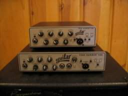
Even then, the circular motion of the airflow (due to spinning fan) will cause some of the heatsink fins to get a lot of air, and others to get a bunch less, in a design such as the one shown.
However, the airflow before the fan, on the "suction" side is very controllable. In fact it is MORE controllable than the airflow on the outlet side aside from outlet ducting.
You simply put holes in the chassis wherever you want airflow. That creates the same sort of local directional airflow that would exist with a fan. You can let it into a duct, or you can have it blow over components that need cooling, etc. You have complete control over airflow.
The key fact here that is being missed is that airflow happens because of a pressure difference. There may be a pressure difference because a fan creates a high pressure area at it's outlet. OR there may be a pressure difference because a fan REMOVES air from an enclosed area. Either way there is flow induced from higher to lower pressure areas.
Getting out of the theoretical and to the practical, The SWR basic plan is a very good one. I have used the same plan in a number of products which have performed very well.
However, I ALWAYS made sure that air which exited the heatsinks ALSO exited the chassis. That is a basic point that is a fault with the SWR, due to the (edit to insert missing text) large gap to the chassis side at the end of the heatsink.
AND, I always made sure that the INCOMING air was directed to cool other items in the chassis such as transformer, power supply, etc. That is another point that was missed by the SWR designer. The incoming air through the large back vent bypasses all the other stuff in the chassis, except insofar as it may swirl around randomly inside.
It is the lack of attention to detail that is the problem, NOT the basic plan of blowing air out through the heatsinks.
An attempt to reverse the fan to pull air IN through the heatsinks might give an improvement of one sort, but at the cost of having hot air actually heating up other components that are now at least somewhat cooled.
Instead, I would add small baffles of insulating material to ensure that all the hot air leaves the chassis. That will make a significant improvement, especially if the rack is modified to allow some airflow away from the vent.
After that, it might not be necessary to add or move any holes in teh chassis, unless the transformer proves to be an issue with overheating and causing shutdowns. if it does, some holes in the back can be closed up and others added to provide airflow over the transformer.
Don't worry about pre-heating the air. If the fan is sufficient as to airflow now (we don't know that, BTW) it will not be a problem, the air won't be pre-heated enough to matter.
While a "screen" top, which is about what that "vegetable drainer" top is, may be better than teh original plan, if the airflow is improved, the "perforated top" will be worse than a properly designed airflow.
All the above is assuming the fan that is there will actually move enough air. It is possible that IT is poorly selected, and isn't doing the job. I would expect that a fan moving about 30 to 40 cubic feet per minute would be needed for good cooling, but that is based on some 'wild guesses" about the heatsink etc. It could be off by 30% or more.



 . I would suggest that bass amps follow a similar life cycle. That said, amps take a lot of abuse, heat, ohm mismatch, transportation, and don't forget sitting on top of a vibrating speaker cabinet show after show, or the occasional beer bath
  etc.
etc.