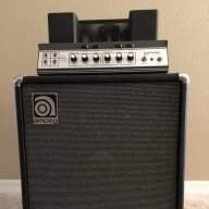
Nice article.
It is reported in the Bass Gear article that the measured 0 dB input impedance and the -15 dB input differ. This has an interesting affect in addition to padding the input. At higher frequencies, the grid resistor and input capacitance combine to form a low pass filter that rolls off the high end. Doing some very rough calculations on the first stage of the V4B, I figure that the cutoff is around 58 kHz for the 0 db input and 10.5 kHz for the -15 B input. The true numbers aren't important. The important thing to note is that the upper frequency of -15 dB input is more limited. Higher frequencies will be attenuated. Designers use this to their advantage. By increasing the grid resistor value, the high pass filter break point changes and upper harmonics are cut off. This can remove unpleasant high frequency distortion making the distortion sound better. Worth experimenting with each input if you are using distortion.
_______________
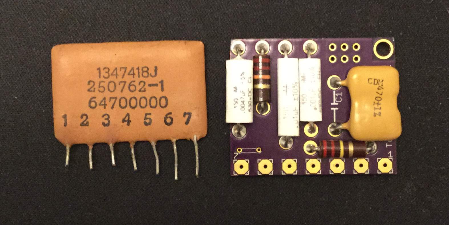
The vintage Ampeg amps used a PEC module manufactured by Centralab for the James tone circuit. An image of a PEC module is included below, on the right of that image is a replacement module. The tolerance on the PEC modules were +/-10% for the resistors. The capacitors tolerance was +50% and -20% in the 1000pF range, and +/- 20% in the 100pF range.
I find that the vintage PEC modules are often uncomfortably far from the nominal values and are inconsistent from one module to the next. This will affect the tone settings. Normally the treble and bass tone controls set at noon is flat but as a result of the drift, this isn't always the case. It can come into play when comparing two amps or even two channels in an amp.
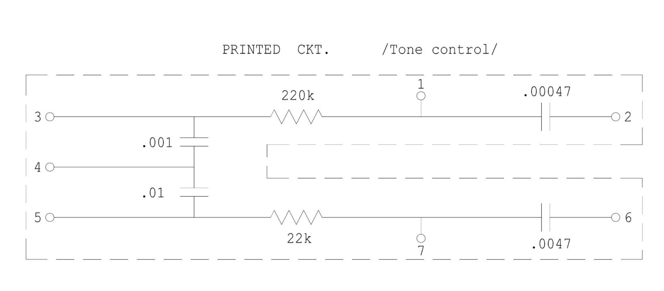
Below I've included the PEC module schematic used in vintage Ampeg amps as well as an image of the PEC module. The PEC module is a small circuit board with carbon composition resistors and ceramic capacitors encased with a brown material that is similar to what was used on vintage ceramic capacitors. The modules were common in radios and TV sets. They made manufacturing a bit easier.
On my '74 V4B for example, I found that the PEC pin readings relative to the nominal values were marginal or out of spec:
1-2 -9%
1-3 -11%
3-4 -30%
4-5 -25%
5-7 +9%
6-7 -19%
Often on even older amps, the readings are worse. Perhaps time takes a toll on them. Old modules can also affect the clarity of the sound making it muddy. A lot of people don't give these modules a second thought, I like to replace them when necessary. One reason why a reissue V4B is better but you can get around the issues found with the vintage amp.
PEC module schematic:
PEC module on the left:
It is reported in the Bass Gear article that the measured 0 dB input impedance and the -15 dB input differ. This has an interesting affect in addition to padding the input. At higher frequencies, the grid resistor and input capacitance combine to form a low pass filter that rolls off the high end. Doing some very rough calculations on the first stage of the V4B, I figure that the cutoff is around 58 kHz for the 0 db input and 10.5 kHz for the -15 B input. The true numbers aren't important. The important thing to note is that the upper frequency of -15 dB input is more limited. Higher frequencies will be attenuated. Designers use this to their advantage. By increasing the grid resistor value, the high pass filter break point changes and upper harmonics are cut off. This can remove unpleasant high frequency distortion making the distortion sound better. Worth experimenting with each input if you are using distortion.
_______________
The vintage Ampeg amps used a PEC module manufactured by Centralab for the James tone circuit. An image of a PEC module is included below, on the right of that image is a replacement module. The tolerance on the PEC modules were +/-10% for the resistors. The capacitors tolerance was +50% and -20% in the 1000pF range, and +/- 20% in the 100pF range.
I find that the vintage PEC modules are often uncomfortably far from the nominal values and are inconsistent from one module to the next. This will affect the tone settings. Normally the treble and bass tone controls set at noon is flat but as a result of the drift, this isn't always the case. It can come into play when comparing two amps or even two channels in an amp.
Below I've included the PEC module schematic used in vintage Ampeg amps as well as an image of the PEC module. The PEC module is a small circuit board with carbon composition resistors and ceramic capacitors encased with a brown material that is similar to what was used on vintage ceramic capacitors. The modules were common in radios and TV sets. They made manufacturing a bit easier.
On my '74 V4B for example, I found that the PEC pin readings relative to the nominal values were marginal or out of spec:
1-2 -9%
1-3 -11%
3-4 -30%
4-5 -25%
5-7 +9%
6-7 -19%
Often on even older amps, the readings are worse. Perhaps time takes a toll on them. Old modules can also affect the clarity of the sound making it muddy. A lot of people don't give these modules a second thought, I like to replace them when necessary. One reason why a reissue V4B is better but you can get around the issues found with the vintage amp.
PEC module schematic:
PEC module on the left:
Last edited: