• TalkBass has been independent since 1998. Add your voice.
    Create a free account to reply to discussions, view embedded media, and browse with fewer display ads.
    Join freeLog in
    Want zero display ads or expanded classifieds tools? Compare plans.

4 way rotary switches

shaft size looks good. will that switching pattern get the job done?
 

Attachments

  • Screen Shot 2015-03-02 at 6.32.44 PM.png
    Screen Shot 2015-03-02 at 6.32.44 PM.png
    193.8 KB · Views: 342
Sorry in advance for hijacking the thread...

I'm looking to do the same thing as the OP. However, I'd also like to include a 10k trim pot to in order to adjust the the level of the 'series' position so that it's no louder than the others. Does anyone know how to wire this up? I'm guessing I need a 3P4T rotary switch, rather than a 2 pole one? Cheers!
 
Just adding resistance to ground when the switch is in the series position won't really be a controllable attenuation. It will simply damp the treble then suddenly kill the volume all together. Nor will just adding some in-line resistance. This will sort of work a little better but the attenuation you get will vary from one amp/pedal/DI to the other, completely dependent on its input impedence. You need two resistors - one in-line, and one to earth, forming a voltage divider. The resistors can be individual fixed resistors, usually around the same value, as this gives 6dB attenuation which is usually about right for this. I've wired this many times over the years. The two resistors can be two halves of a pot as well. I've never tried this, but I'd think a 200K trimmer pot would be ideal.

You'll need a 4 pole switch. I think if you went with a couple of fixed resistors instead of a trimpot, you could get away with 3 poles, and have your four positions, but really, I wouldn't bother with a 4 position switch. The difference in tone between one single coil and the other is negligible. And you can get a 4P3T for just a few bucks on ebay. I'm lucky, [Invalid or Expired Link Removed]

Here's a wiring for a MM triple coil that I often use. If you have trouble adapting it for your use, I might get time tomorrow to scribble out a specific diagram for you...
Music man triple coil - revised 6 oct 2011.jpg


If you decide to go with a pair of fixed resistors and your bass is passive, instead of 68K, go with larger resistors - 100K I'd think.

PS: FWIW, notice that the dummy coil is in series with the bridge coil when in single coil mode. This is a really nice way to do a triple-coil MM pickup...
 
Last edited:
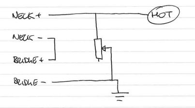
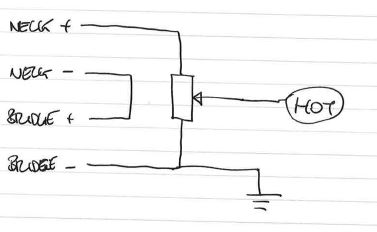
Thanks for the input guys. RobbieK, to check that I am understanding correctly, are you saying that this is undesirable:

and what I do need is actually this:
?

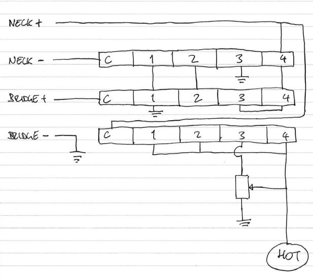
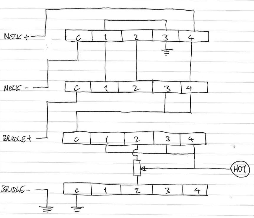
If that is the case, can I wire a 3P4T switch like so:

The variable pot in the last picture is intended to be a 200k trimmer. I like your suggestion of using two sides of one variable pot - very elegant (because this would give precise control of the series level, especially if a multi-turn pot was used, right...?).

If I have it right (this is based on Casablancas' last diagram), this should give

Position 1: Neck only
Position 2: Series
Position 3: Parallel
Position 4: Bridge only

I do want to keep all four switching options if possible.

Thanks again!
 
the trouble with your wiring is that the hot output is permanently connected to earth with half of the trimpot resistance. this will dull the tone of the parallel and single coil modes.

you need that 4th pole to disconnect the trimpot altogether when not needed. with the diagram I posted, you can see that a couple of fixed resistors can be totally bypassed without needing the extra pole. (the extra pole in this case is used for the dummy coil.)

As I said, if you really need both single coils and a trimpot you'll have to find a 4p4t switch.