• TalkBass has been independent since 1998. Add your voice.
    Create a free account to reply to discussions, view embedded media, and browse with fewer display ads.
    Join freeLog in
    Want zero display ads or expanded classifieds tools? Compare plans.

5-String Fanned Hybrid Headless

So, onward and upward…

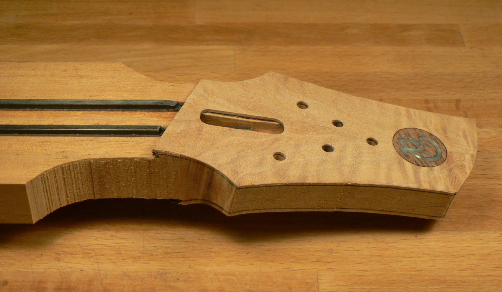
I cut out the headstock shape leaving about 2mm extra all round.
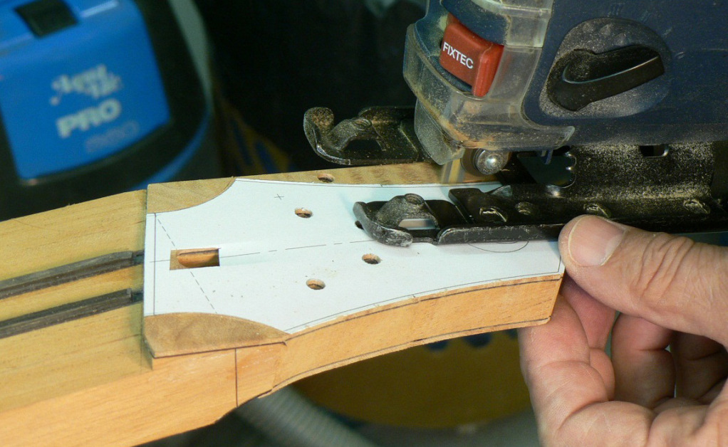
HFN050.jpg


HFN051.jpg


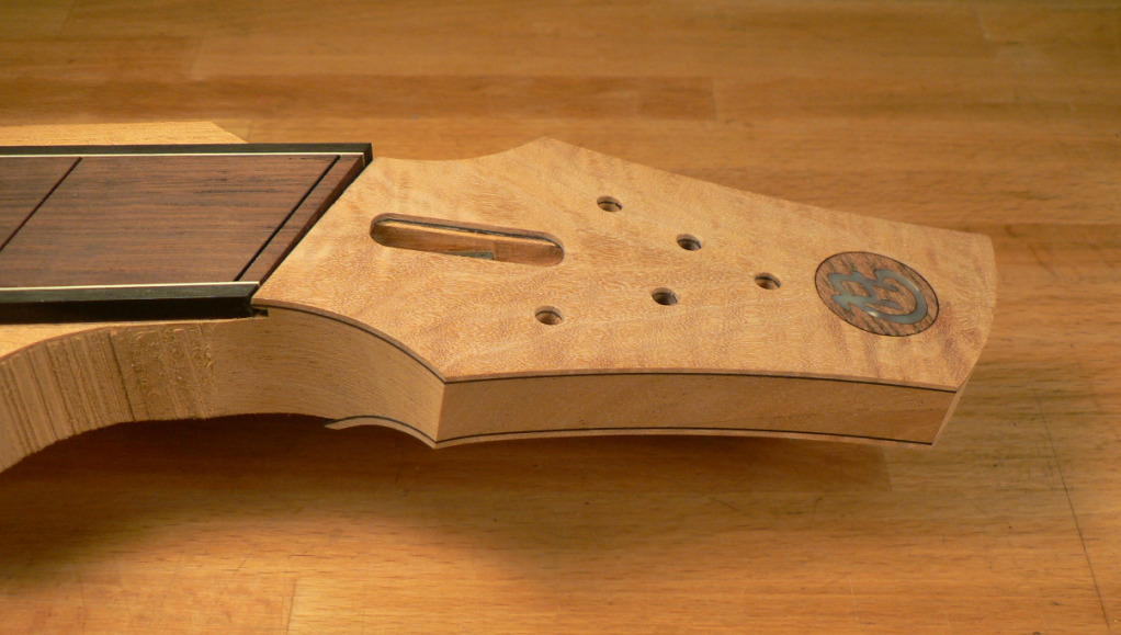
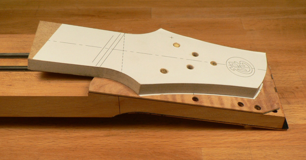
Then I made a template for the headstock shape. It’s held in position by dowels in pilot holes for the string anchors.
HFN049.jpg


And routed the finished shape. This was done face down on the router table. It’s really worth making a simple router table for this sort of job. Using a hand-held router for this would be very risky, as it would be too easy for the router to tilt and ruin the outline. On the router table it’s a doddle.

HFN052.jpg


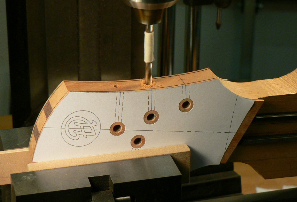
The strings will be held in ferrules with Allen setscrews (grubscrews). These are the access holes for the grubscrews.
HFN053.jpg


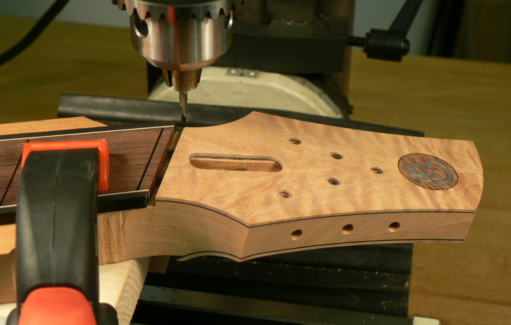
Before gluing the fingerboard on, I set it up on the milling machine and ran a cutter through skimming the end of the fingerboard and the edge of the headstock veneer. This should give me a perfectly square and parallel slot for the nut.
HFN054.jpg


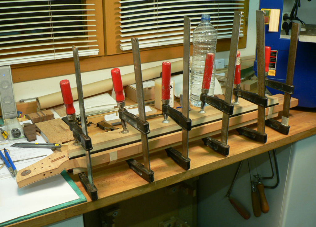
Then I glued the fingerboard on. This is just to show you what it looks like when I don’t tidy up for the photo.

HFN055.jpg
 
  • Like
Reactions: Rob Page
Er… where was I? Oh yes! On to the next minor disaster…

When I glued the fingerboard on I masked off the neck and fingerboard and the nut area to make it easier cleaning up glue squeeze-out. The fingerboard was prevented from moving around by the CF bars in their slots and I drilled two tiny holes for panel pins through the zero-fret slot to prevent it moving lengthwise. You can perhaps see two holes in the clamping caul in the last photo.

I wasn’t careful enough pulling out the first of the two panel pins (even though I’d already thought that the zero fret was too near the end of the fingerboard) and this is what happened. :mad:

HFN056.jpg


But I had one small stroke of luck. I hadn’t removed that last bit of masking tape. There were bits of fingerboard, a bit of purfling and a bit of binding all stuck to it.

HFN057.jpg


So I carefully pressed it all back into place and applied a couple of drops of water-thin CA.

HFN058.jpg


Peeled the masking tape off, gave it a rub with a sanding block and it looks as if it never happened. Mind you, when it comes to installing the zero fret, I think I’ll file the barbs down and glue it in. ;)

HFN059.jpg
 
  • Like
Reactions: Rob Page
I made a new router table. It’s just as basic as the other one but it’s bigger and easier to set up. So after having cut off the surplus on the band-saw, I routed the neck flush with the fingerboard.

HFN061.jpg


My workshop is so small and crowded that when I’m working on one end of the neck I keep dinging the other end. I’ve already had to re-do the curve at the top of the headstock so this is what it looks like now.

HFN062.jpg


The neck routed flush to the fingerboard and the extension (up to the neck pickup) reduced in width.

HFN063.jpg


Extension reduced in thickness and the corners of the neck/fingerboard radiused. This was mostly done on the milling machine but the corners were radiused by hand using a tiny plane and sanding sticks.

HFN064.jpg


Reduced the neck,from the back, to final thickness where it fits into the neck pocket using the router sled.

HFN065.jpg


Cut off the surplus and this end is nearly done.

HFN066.jpg
 
I may have missed it somewhere along the way, but I'm curious why you have not filled the fret lines yet. To me it would seem easier to have done that before the banding was applied. My bet is that you have thought this out quite thoroughly already.

The title says headless not fretless. :)


I think the "headless" name is getting a bit confusing. There are quite a few headless basses out there with a headstock. "Tuners-at-the-head-less", perhaps? :smug:
 
I think the "headless" name is getting a bit confusing.

Yes, I think you're right. I called it a 'hybrid headless' because that's the term Maurizio uses and I thought perhaps it was the accepted name.

Now back to the body and a lot of router templates. I started by making a template to rout a recess for the bridge. I stuck a piece of the plan to a piece of MDF, stuck the bridge in place using double sided tape and surrounded it by strips of wood screwed down to the MDF.

HFB010.jpg


Then I took the bridge out and routed inside the strips to make the template.

HFB011.jpg


HFB012.jpg


I decided to make the tops of the bridge and pickups more or less parallel to the string paths, so this meant raising the template at one end. I found out how much from my CAD drawing and stuck some small blocks of the right thickness to the back of the template. The body has two holes in it for location dowels. One is where a tone control will be and the other is where a neck screw will be in the area of the neck pocket. These were used to locate the body profile template when cleaning up the profile on the router table (I forgot to write that up, or take photos) and I’m also using them to locate the templates for routing for the bridge and pickups. The brass dowel pins are a tight fit so I don’t need to stick the templates down.

HFB013.jpg


Here’s the template in place ready to route the bridge recess. I used a 16mm (5/8”) cutter and finished the corners with the 3/8” cutter from Stewmac.

HFB014.jpg


I followed the same procedure for the pickup recesses except that I hogged some of the wood out with a Forstner bit before routing. So here are the bridge and pickup routes done. The pickup routes are rather deep and I had to pull the router cutter out of the collet more than I would have liked, but I managed it. I really need a longer 5/8” and 3/8” cutter but haven’t found any so far.

HFB015.jpg
 
The tuner block is set in at a fairly steep angle so the template had to be made with some wedges under it.

HFB015a.jpg


This meant it couldn’t be located using the dowel pins so it had to be carefully positioned and clamped in place. I decided it would be better to do the round-over in this area before routing for the tuner block although I didn’t take any photos. It’s a ½” radius round the front of the treble side and part of the bass side. The rest will be done later.

HFB016.jpg


This is the result.

HFB017.jpg


Next was the neck pocket. (Before starting on it I marked out and drilled the rest of the holes for the neck screws.) The same procedure was used to make the template. Here the template blank is dowelled to the body and the neck is being aligned with the body. Then strips were screwed to the template butting up to the neck and the neck profile routed into the template as before.

The geometry of the bridge and body was such that if the fingerboard were parallel to the top of the body, the underside of the fingerboard would be 4mm (5/32”) above the body so I decided to set the neck at an angle and bring it down flush with the body.

I didn’t calculate a neck angle. It seems to me that there’s no point in calculating a neck angle and finding it comes to, for instance, 1.673° which would be impossible to measure accurately. This is where CAD is so useful. In my drawing I moved the neck to be flush with the body and then rotated it until the surface of the fingerboard aligned with the top of the bridge. From this line and a line parallel to the top of the body I can draw in spacers of different thicknesses between the two lines and the CAD programme tells me how far apart to position them.

I probably didn’t explain that very well, but in this photo you can see the resulting blocks glued under the template.

HFB018.jpg


So after all that, this is what the body looks like now.

HFB019.jpg
 
  • Like
Reactions: Rob Page and wraub
Yes, I think you're right. I called it a 'hybrid headless' because that's the term Maurizio uses and I thought perhaps it was the accepted name...

I actually made it up. I've got this obsession with thinking up names :D Not that I like the word 'hybrid' that much. But that was the only one that made sense to me.

Dave, the bass is looking great! superb!
 
Subscribed.

Having owned a couple of Steinbergers and a Dingwall in the past my dream bass has always been a headless, fanned-fret fiver! Thanks a lot for fueling my gas. :bassist:

My compliments on the great work you are doing. I'm looking forward to the finished product.

(BTW, on my dream bass will be fiber-optic dot inlays lit by a multi-color LED light source with a knob for changing the colors. One day...)

Raz
 
Time I got this thread going again, and thank you for the compliments.

Moving on to the control cavity. The template for this was made by sticking a drawing to a piece of MDF and cutting the shape out by hand.

HFB020a.jpg


The control cavity cover was made from an off-cut of the alder back.

HFB021a.jpg


To make a routing template for it I wrapped the curved side of it in painter’s tape; both sides and the edge. Three sides of it are straight so strips of wood were butted up to them and screwed down. A fourth strip was profiled to the same approximate curve and then spread with a layer of polyester mastic used for car-body repairs (Bondo?). This was then pushed up against the curved surface, screwed down and left to harden. When it became rubbery and started to harden I trimmed off the surplus that squeezed out.

HFB022a.jpg


When the mastic was hard I took off the straight strip and pulled out the control cover, and screwed the straight strip back in place.

HFB023a.jpg


Then I routed the template on the router table. As you can see, the MDF template has already served in trials for other routing operations.

HFB024a.jpg


Fixed the template to the body (still using the dowels) and routed the recess for the cover.

HFB025a.jpg


The cover will be held in place by small magnets so I stuck the cover to a piece of MDF using double sided tape and routed round it to make another template. I marked out the positions of the magnet holes and drilled them through the template and into the cover.

HFB028a.jpg


Then I took the template off the cover, turned it over, fitted it into the recess in the body and drilled the holes through the template and into the recess. (You’ll notice that I’d also gone round part of the back of the body with the ½” round-over cutter.)

HFB026a.jpg


I fitted the magnets in the cavity cover and the recess. They were quite a tight fit so I pushed them just below the surface and then wicked a drop of thin CA around each one.

HFB027a.jpg


I covered the inside face of the cover with copper shielding foil and stuck some temporary strips of copper foil onto the ledge where the cover sits.

HFB029a.jpg


So now when the cavity cover is in place, it sits slightly proud of the back.

HFB030a.jpg


So I sent it through the sander a few times until it was flush. The cover turned out to be quite a good fit.

HFB031a.jpg
 
Absolutely brilliant work!

This is one of those cases where I see other peoples work and really wish that I had thought of the same thing during my own projects. Thinking especially about using bondo to replicate curves.
 
That control cavity cover jig is brilliant. It's seems so simple how you put it together, but that idea would have never dawned on me :smug:. Great job!

Also, I know it's been said a hundred times already, but I am impressed by how neat and tidy your work is (both the bench top work space and the bass itself!)

I'm really looking forward to seeing this one finished.
 

Latest posts